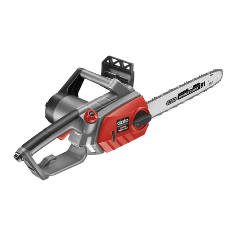
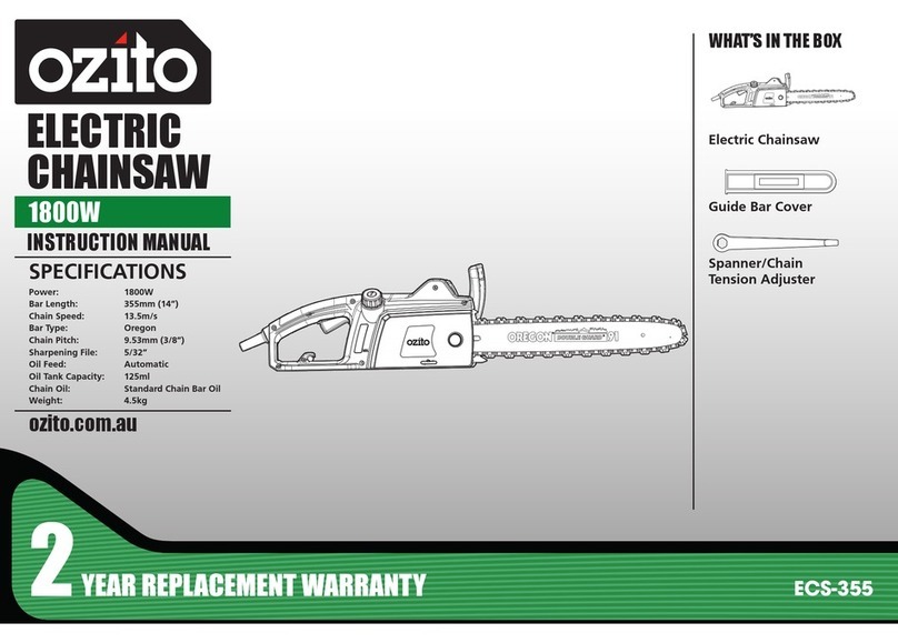
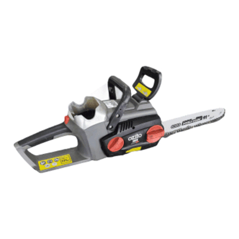
Ozito PXCCSS-018 User manual

SPECIFICATIONS
Input: 18V
Bar Length: 250mm (10”)
Cutting Length Max.: 230mm
Chain Speed: 4.3m/s
Chain Pitch: 9.53mm (3/8”)
Chain Gauge: 1.1mm (.043”)
Oil Tank Capacity: 200ml
Weight: 3.0kg
STANDARD EQUIPMENT
Chainsaw
CORDLESS
CHAINSAW
INSTRUCTION MANUAL
ozito.com.au
Guide Bar Cover
Screwdriver
PXCCSS-018
IN ORDER TO MAKE A CLAIM UNDER THIS WARRANTY YOU
MUST RETURN THE PRODUCT TO YOUR NEAREST BUNNINGS
WAREHOUSE WITH YOUR BUNNINGS REGISTER RECEIPT. PRIOR TO
RETURNING YOUR PRODUCT FOR WARRANTY PLEASE TELEPHONE
OUR CUSTOMER SERVICE HELPLINE:
Australia 1800 069 486
New Zealand 0508 069 486
WARRANTY
TO ENSURE A SPEEDY RESPONSE PLEASE HAVE THE MODEL
NUMBER AND DATE OF PURCHASE AVAILABLE. A CUSTOMER
SERVICE REPRESENTATIVE WILL TAKE YOUR CALL AND
ANSWER ANY QUESTIONS YOU MAY HAVE RELATING TO THE
WARRANTY POLICY OR PROCEDURE.
OZITO Australia/New Zealand (Head Ofce) 1-23 Letcon Drive, Bangholme, Victoria, Australia 3175.
The benets provided under this warranty are in addition to other rights and
remedies which are available to you at law.
Our goods come with guarantees that cannot be excluded at law. You are entitled to
a replacement or refund for a major failure and for compensation for any other
reasonably foreseeable loss or damage. You are also entitled to have the goods
repaired or replaced if the goods fail to be of acceptable quality and the failure
does not amount to a major failure.
Generally you will be responsible for all costs associated with a claim under this
warranty, however, where you have suffered any additional direct loss as a result of
a defective product you may be able to claim such expenses by contacting our
customer service helpline above.
0718
WARNING
The following actions will result in the warranty being
void.
• If the tool has been operated on a supply voltage other
than that specied on the tool.
• If the tool shows signs of damage or defects caused
by or resulting from abuse, accidents or alterations.
• Failure to perform maintenance as set out within the instruction manual.
• If the tool is disassembled or tampered with in any way.
• Professional, industrial or high frequency use.
5 YEAR REPLACEMENT WARRANTY
Your Product is guaranteed for a period of 60 months from the original date of
purchase and is intended for DIY (Do It Yourself) use only. If a product is defective it
will be replaced in accordance with the terms of this warranty. Lithium Ion
batteries and chargers are covered by a 36 month
warranty Warranty excludes consumable parts, for example: guide bar, chain
and included accessories.
10
in
250
mm
3/8”LP
40
10
in
250
mm
3/8” LP
40

10
in
250
mm
3/8” LP
40
KNOW YOUR PRODUCT SETUP & PREPARATION
1. INSERTING & REMOVING BATTERY
1. Rear Handle
2. Trigger Switch
3. Oil Level Window
4. Chain Oil Tank Cap
5. Side Cover
6. Front Handle
7. Chain Brake
8. Guide Bar Locking Knob
9. Guide Bar
10. Chain
11. Bucking Spikes
12. Motor Cover
13. Lock-Off Button
14. Battery Seating
CORDLESS CHAINSAW
1 2 3 4 5 6 7 8
BATTERY & CHARGER
This tool is compatible with all battery and chargers from the Ozito
Power X Change Range.
ONLINE MANUAL
Scan this QR Code with your
mobile device to take you to the
online manual.
ACCESSORIES
15 Guide Bar Cover 16 Screwdriver
15 16
10
11 12 13 14
9
10
in
250
mm
Installing a Battery into the Chainsaw
1. Align the ribs of the battery with
the recess below the handle
Removing a Battery from the Chainsaw
2. Slide the battery in so
that it clicks into place.
1. Press and hold the battery
release tab to release the
battery.
2. Slide the battery out.

2. OIL 3. SWITCHING ON/OFF
OPERATION
Running in the Chain
Prior to operation, a new chain should be run in for 2–3 minutes and then its
tension should be checked and adjusted as detailed in “MAINTENANCE”.
Note: Chain bar oil may leak if the tool is left for long periods. This is
normal. If the tool is to be left unused for an extended time, drain the oil from
the tool. Rell before use.
Switching ON
1. Pull the hand guard/chain brake
towards you.
2. Hold the front handle with your
left hand and the rear handle
with your right hand.
Switching OFF
1. Release the trigger switch, the
chain and motor will quickly stop.
10
in
250
mm
3/8”LP
40
10
in
250
mm
3/8”LP
40
10
in
250
mm
3/8”LP
40
10
in
250
mm
3/8”LP
40
10
in
250
mm
3. Press the lock-off button with
your thumb, then squeeze the
trigger switch. The chainsaw
starts after a short delay.
4. The chain will now be running,
ready to make a cut. Release
the lock-off switch.
5. To check the lubricating system,
switch on the chainsaw and hold it
with the guide bar and chain above
some light coloured paper such as
newspaper. A steadily increasing
stain caused by oil spray shows
the lubricating system is working.
2. Fill the tank with chain bar oil.
The capacity of the chain oil
tank is 220ml. Do not over ll.
4. Always ll the oil tank when the
oil level is below the minimum
mark on the oil level window.
WARNING!: NEVER START WORK UNLESS THE
CHAIN AND BAR ARE LUBRICATED
1. Remove the chain bar oil cap.
3. Ret cap and clean any oil
spillage.
IMPORTANT: ONLY USE OIL THAT IS EXPRESSLY LABELLED
“CHAIN BAR OIL”.
10
in
250
mm
3/8” LP
40
10
in
250
mm
3/8”LP
40
10
in
250
mm
3/8”LP
40
10
in
250
mm
3/8”LP
40
10
in
250mm
10in
250
mm

RUN
BRAKE ON BRAKE OFF
STOP
10
in
250
mm
3/8”LP
40
5. CUTTING
4. CHAIN BRAKE
10
in
250
mm
The chain brake operates automatically in the event of kick back.
The chainsaw is tted with a hand guard/chain brake which when operated
brings the chain to a stop within a tenth of a second.
The chain brake can be operated manually by pushing it forward or
automatically as a result of kickback.
Kickback occurs if the chain catches on the wood being cut and the chainsaw
recoils back suddenly.
In the event of kickback, your hand (which is on the front handle during
operation) jerks forward causing the back on your hand to push the guard
forward, engaging the chain brake and quickly stopping the chain.
10
in
250
mm
3/8”LP
40
10
in
250
mm
3/8”LP
40
10
in
250
mm
3/8”LP
40
10
in
250
mm
3/8”LP
40
10
in
250
mm
3/8”LP
40
10
in
250
mm
3/8”LP
40
2. Start cutting by holding the
chainsaw by the front handle
and raising the rear handle.
1. Press the bucking spikes against
the timber ensuring the chain
is not making contact with the
material being cut.
3. If you cannot cut the timber
in a single stroke, apply
light pressure to the front
handle and continue sawing,
draw the chainsaw back a
little then apply the bucking
spikes a little lower and
nish the cut by raising the
rear handle.
4. Withdraw the chainsaw from
the cut while the chain is still
running.
10
in
250
mm
3/8”LP
40
10
in
250
mm
3/8”LP
40
10
in
250
mm
3/8”LP
40
Hints and Tips
• Do not force the saw into the cut. Apply only light pressure whilst running
the chain.
• If the saw chain gets caught in the cut, do not try to remove it by twisting
the guide bar or pulling forcibly. Use a lever or wedge to open up the cut
so that the saw chain is freed.
• Keep your left arm with elbow locked in a “straight arm” position to
withstand any kickback force.
• While cutting, always:
– Run the chainsaw motor at full speed. This makes the job safer, as there
is less chance of pull-in or kick-back.
– Position your body to the left of
the chainsaw so if it kicks back
uncontrollably, it goes over your right
shoulder, never stand in the cutting line
of the saw.
– Keep a rm grip with your left hand
on the front handle, with your thumb
securely below the handle.
LEFT HAND
CUTTERS
STRAIGHT
ARM
POSITION
CHAIN
LINE
RIGHT HAND
CUTTERS
30°
30°
CAUTION: FIRST TIME USERS SHOULD, AS A MINIMUM
PRACTISE, CUT LOGS ON A SAW-HORSE OR CRADLE

PXCCSS-018
1
21
2
APPLICATIONS
Pruning
Felling a Tree
Decide the direction in which you wish the tree to fall, taking into account
the direction of the wind, the position of branches, lean of the tree, ease
of subsequent limbing and
bucking and other factors
prevalent at the time. Pruning is the removal of a limb or
branch from a standing tree.
WARNING!: FELLING A TREE SHOULD ONLY BE
DONE BY TRAINED OPERATORS.
Limbing
WARNING!: FELLING ALWAYS KEEP A BALANCED
STANCE. DO NOT STAND ON THE LOG. BE ALERT TO
THE FACT THAT THE LOG MAY ROLL OVER. WHEN
WORKING ON A SLOPE, ALWAYS STAND ON THE UP HILL
SIDE OF THE LOG.
Limbing is the process of removing the branches from a fallen tree. Check
the direction in which a branch will bend before cutting it. Always cut on the
opposite side to the bending direction so that the guide bar is not pinched in
the cut. For large limbs that cannot be removed in one cut, make an initial cut
from the bent side and nish
by sawing from the opposite
direction. Do not remove
limbs that are supporting the
fallen tree on the ground until
the tree has been cut into
lengths.
1
2
Bucking
Bucking is cutting a log into lengths for easier handling. To saw a log lying
on the ground, rst saw halfway, then roll the log over and cut from the
opposite side. To saw the end of a log
supported off the ground, rst saw up
from the bottom one-third through the
log then nish by sawing down from
the top. To saw a log in the middle
of two supports holding it off the
ground, rst saw down from the top
one-third through the log then nish
by sawing up from the bottom.
CAUTION: FIRST AVOID CUTTING THE GROUND AS THIS
WILL VERY QUICKLY DULL THE SAW CHAIN.
WARNING!: DO NOT USE AN UNSTABLE FOOTHOLD
OR LADDER. DO NOT OVERREACH. DO NOT SAW
ABOVE SHOULDER HEIGHT. ALWAYS USE BOTH
HANDS TO HOLD THE SAW. FIRST CUT UP FROM THE
BOTTOM AND FINISH DOWN FROM THE TOP.
1
2

WARNING: BEFORE CLEANING YOUR CHAINSAW OR
CARRYING OUT ANY MAINTENANCE PROCEDURE,
MAKE SURE THE BATTERY REMOVED TO PREVENT
ACCIDENTAL STARTING.
CAUTION: ALWAYS WEAR GLOVES WHEN HANDLING
THE CHAIN AS IT IS VERY SHARP AND CAN CUT YOU
WHEN IT IS NOT MOVING.
Adjusting the Chain Tension
1. Loosen the guide bar locking knob
slightly, by rotating it in an anti
clockwise direction.
2. Adjustment chain tension screw
CLOCKWISE to increase chain tension.
Turning screw COUNTERCLOCKWISE
will decrease amount of tension on
the chain. Adjust the chain tension
screw for the correct tension.
3 - 4mm gap is
the ideal tension
For the correct chain tension, pull up on
the chain from the top and middle of the
exposed guide bar. The bottom tip of the
links should only just stay in the track.
3. After the chain has been accurately
tensioned, lock the guide bar in place
with the guide bar locking knob.
Note: Proper tension of the chain is extremely important and must be
checked before starting, as well as during any cutting operation.
Taking the time to make adjustments to the chain will result in
improved cutting performance and prolonged chain life.
MAINTENANCE TROUBLESHOOTING
Battery protection system
The tool is equipped with the battery protection system, which helps to ensure a long service
life.
The output power automatically cuts off during operation when the tool and/or battery are
placed under the following situations:
• When the tool is overloaded:
If this occurs, release the trigger switch and remove causes of overload, then pull the
switch trigger again to restart.
• When the remaining battery capacity becomes low:
Recharge the battery pack.
Note: The battery protection system does not in any way damage the tool.
Note: The indicated capacity may be lower than the actual level during use or immediately
after using the tool.
Maintaining the guide bar
1. Remove any sawdust from the guide bar, including the groove.
Oil and sawdust combine and emit a burning smell during operation if the blade is not
regularly cleaned.
2. Make sure that the oil port is not clogged. Grease the nose sprocket at the tip of the
guide bar.
3. Check for oil leakage and loose fastenings, especially those securing the handles and
the guide bar.
4. Reverse the guide bar every 8 working hours to ensure uniform wear. Check the guide
rails frequently and if necessary remove burrs and square up the rails using a at le.
Chain Sharpening
Chain File: 3.96mm (5/32”)
Chain Pitch: 9.53mm (3/8”)
Chain Gauge: 1.1mm (0.043”)
Sharpen the chain regularly to maintain
optimum performance of the saw. Signs of a
dull chain are:
• The sawdust becomes powder-like
• Extra force is required to execute a cut
• The cut does not track in a straight line
• Increased vibration
Sharpen each cutter using a round 3.96mm (5/32”) chain le. Keep the le level with the
top plate of the tooth. Always use outward strokes and maintain a 30° angle between the
chain and le. After sharpening, the cutters must all have the same width and length.
After every 3–4 uses get an authorised repair centre to professionally sharpen your chain.
They have the special tools necessary to ensure the correct cutting angles and depths.
LEFT HAND
CUTTERS
STRAIGHT
ARM
POSITION
CHAIN
LINE
RIGHT HAND
CUTTERS
30°
30°
Cleaning and storing
• Keep the handles free of grease so that you can maintain a rm grip.
• Clean the device as required with a damp cloth and, if necessary, mild washing up
liquid.
• If the chainsaw is not to be used for an extended period of time
then you should remove the chain oil from the tank. Briey immerse the chain and
the cutter rail in an oil bath and then wrap them
in oil paper.
• Ensure that the guide bar cover is in place when storing.
CAUTION! ALWAYS DISCONNECT THE BATTERY BEFORE
CLEANING THE CHAINSAW.
CAUTION! NEVER IMMERSE THE UNIT IN WATER OR
OTHER LIQUIDS IN ORDER TO CLEAN IT.
CAUTION! STORE THE CHAINSAW IN A SAFE AND DRY
PLACE OUT OF THE REACH OF CHILDREN.
LED lights do not illuminate on charger
Check the charging adaptor is securely plugged into the wall outlet.
Check the battery is rmly connected to the charging cradle.
Check that the charging jack is securely connected to the charging cradle.
The battery has a short run time
Ensure the battery is properly charged. It will take 4-5 charging cycles before the battery
reaches optimum charge and run time.
Sparking visible through the housing air vents
A small amount of sparking may be visible through the housing vents. This is normal and
does not indicate a problem.

BATTERY AND CHARGER SAFETY WARNINGS
THIS MANUAL CONTAINS IMPORTANT SAFETY AND OPERATING INSTRUCTIONS FOR
YOUR BATTERY CHARGER.
1. Before using the charger read all instructions and cautionary markings on the charger, battery pack and the product
using the battery pack.
2. This charger is not intended for any uses other than charging rechargeable batteries. Any other use may result in risk of
re, electric shock or electrocution.
3. Do not place any object on top of the charger or place the charger on a soft surface that may result in excessive internal
heat. Place the charger in a position away from any heat source.
4. To reduce risk of damage to the electric plug and cord, pull by the plug rather than the cord when disconnecting the
charger.
5. Make sure the cord is located so that it will not be stepped on, tripped over, or otherwise subjected to damage or stress.
6. An extension cord should not be used unless absolutely necessary. Use of an improper extension cord could result in the risk
of re, electric shock or electrocution.
7. Do not operate the charger if it has received a sharp blow, been dropped or otherwise damaged in any way. Have it
checked by an electrician or power tool repairer.
8. Do not disassemble charger. Take it to an electrician or power tool repairer when service or repair is required. Incorrect
reassembly may result in a risk of electric shock, electrocution or re.
9. To reduce risk of electric shock, unplug the charger from the outlet before attempting any cleaning. Removing the
battery pack will not reduce this risk.
10. Never attempt to connect 2 chargers together.
11. DO NOT store or use the tool and battery pack in locations where the temperature may reach or exceed 40ºC (such as inside
sheds or metal buildings in summer).
12. The charger is designed to operate on standard household electrical power (240 volts). Do not attempt to use it on any
other voltage!
13. The battery pack is not fully charged out of the carton. First read the safety instructions and then follow the charging
notes and procedures.
14. The longest life and best performance can be obtained if the battery pack is charged when the air temperature is
between 18 - 24ºC. Do not charge the battery pack in an air temperature below 10ºC or above 40ºC. This is important
and will prevent damage to the battery pack.
15. Do not incinerate the battery pack even if it is seriously damaged or is completely worn out. The battery can explode in a
re.
16. Never attempt to open the battery pack for any reason. If the plastic housing of the battery pack breaks or cracks, immediately
discontinue use and do not recharge.
17. During charging, the battery must be placed in a well ventilated area.
Wear ear muffs & safety glasses
Read instruction manual
Do not saw in the rain or leave the chainsaw outdoors while raining.
Always hold the saw with both hands
Regulator compliance mark
Wear safety gloves
CARING FOR THE ENVIRONMENT
Power tools that are no longer usable should not be disposed of with household waste
but in an environmentally friendly way. Please recycle where facilities exist. Check
with your local council authority for recycling advice.
Recycling packaging reduces the need for landll and raw materials. Reuse of recycled
material decreases pollution in the environment. Please recycle packaging where
facilities exist. Check with your local council authority for recycling advice.
SPARE PARTS
Chain Replacement:
The chain can be purchased through Ozito spare parts or from your local Bunnings
Warehouse. The correct chain can be purchased by matching the pitch, gauge and
number of links as shown below:
Spare parts can be ordered from the Special Orders
Desk at your local Bunnings Warehouse.
For further information, or any parts not listed here,
visit www.ozito.com.au or contact Ozito Customer
Service:
Australia 1800 069 486
New Zealand 0508 069 486
E-mail: [email protected]
2
9.53 mm(3/8) 1.1 mm(.043”) 40 Links
DESCRIPTION OF SYMBOLS

CHAINSAW SAFETY WARNINGS
• Keep all parts of the body away from the saw chain when the chain saw is
operating. Before you start the chain saw, make sure the saw chain is not
contacting anything.
A moment of inattention while operating chain saws may cause entanglement of your clothing or body with the saw
chain.
• Always hold the chain saw with your right hand on the rear handle and you left
hand on the front handle. Hold the chain saw with a reversed hand conguration increases the risk of
personal injury and should never be done.
• Hold the power tool by insulated gripping surfaces only, because the chain may
contact hidden wiring. Saw chains contacting a “live” wire may make exposed metal parts of the power tool
“live” and could give the operator an electric shock.
• Wear safety glasses and hearing protection. Further protective equipment for
head, hands, legs and feet is recommended. Adequate protective clothing will reduce personal injury
by ying debris or accidental contact with the saw chain.
• Do not operate a chainsaw in a tree. Operation of a chainsaw while up in a tree may result in personal
injury
• Always keep proper footing and operate the chainsaw only when standing on fixed,
secure and level surface. Slippery or unstable surfaces such as ladders may cause a loss of balance or
control of the chain saw.
• When cutting a limb that is under tension be alert for spring back. When the tension in
the wood bres is released the spring loaded limb may strike the operator and/or throw the chain saw out of control.
• Use extreme caution when cutting brush and saplings. The slender material may catch the saw
chain and be whipped towards you or pill you off balance.
• Carry the chain saw by the front handle with the chain saw switched off and away
from your body. When transporting or storing the chain saw always t the guide bar cover. Proper handling of
the chain saw will reduce the likelihood of accidental contact with the moving saw chain.
• Follow instructions for lubricating, chain tensioning and changing accessories.
Improperly tensioned or lubricated chain may either break or increase the chance for kickback
• Keep handles dry, clean, and free from oil and grease. Greasy, oily handles are slippery causing
loss of control.
• Cut wood only. Do not use chain saw for purposes not intended. For example: do not use
chain saw for cutting plastic, masonry or non-wood building materials. Use of the chain saw for operations different
than intended could result in a hazardous situation.
Causes and operator prevention of kickback
Kickback may occur when the nose or tip of the guide bar touches an object, or when the wood closes in and pinches the
saw chain in the cut.
Tip contact in some cases may cause a sudden reverse reaction, kicking the guide bar up and back towards the operator.
Pinching the saw chain along the top of the guide bar may push the guide bar rapidly back towards the operator.
Either of these reactions may cause you to lose control of the saw which could result in serious personal injury. Do not rely
exclusively upon the safety devices built into your saw. As a chain saw user, you should take several steps to keep your
cutting jobs free from accident or injury.
Kickback is the result of tool misuse and/or incorrect operating procedures or conditions and can be avoided by taking proper
precautions as given below:
• Maintain a firm grip, with thumbs and fingers encircling the chain saw handles,
with both hands on the saw and position your body and arm to allow you to resist
kickback forces. Kickback forces can be controlled by the operator, if proper precautions are taken. Do not let go
of the chain saw.
• Do not overreach and do not cut above shoulder height. This helps prevent unintended tip
contact and enables better control of the chain saw in unexpected situations.
• Only use replacement bars and chains specified by the manufacturer. Incorrect
replacement bars and chains may cause chain breakage and/or kickback.
• Follow the manufacturer’s sharpening and maintenance instructions for the saw
chain. Decreasing the depth gauge height can lead to increased kickback.
This appliance is not intended for use by persons (including children) with reduced physical, sensory or mental capabilities,
or lack of experience and knowledge, unless they have been given supervision or instruction concerning use of the appliance
by a person responsible for their safety.
WARNING! When using mains-powered tools, basic safety precautions, including
the following, should always be followed to reduce risk of fire, electric shock, personal
injury and material damage.
Read the whole manual carefully and make sure you know how to switch the tool off in an emergency, before operating the tool.
Save these instructions and other documents supplied with this tool for future reference.
The charger has been designed for 230V and 240V only. Always check that the power supply corresponds to the voltage on the rating
plate.
Note: The supply of 230V and 240V on Ozito tools are interchangeable for Australia and New Zealand.
This tools charger is double insulated; therefore no earth wire is required.
If the supply cord is damaged, it must be replaced by an electrician or a power tool repairer in order to avoid a hazard.
Note: Double insulation does not take the place of normal safety precautions when operating this tool. The insulation system is for
added protection against injury resulting from a possible electrical insulation failure within the tool.
The power supply for this products charger should be protected by a residual current device (rated at 30mA
or less). A residual current device reduces the risk of electric shock.
GENERAL POWER TOOL SAFETY WARNINGS
ELECTRICAL SAFETY
WARNING! Read all safety warnings and all instructions. Failure to follow the warnings and
instructions may result in electric shock, re and/or serious injury.
Save all warnings and instructions for future reference. The term “power tool” in the
warnings refers to your mains-operated (corded) power tool or battery-operated (cordless)
power tool.
1. Work area safety
a. Keep work area clean and well lit. Cluttered or dark areas invite accidents.
b. Do not operate power tools in explosive atmospheres, such as in the presence of
flammable liquids, gases or dust. Power tools create sparks which may ignite the dust or fumes.
c. Keep children and bystanders away while operating a power tool. Distractions can cause you to lose
control.
2. Electrical safety
a. Power tool plugs must match the outlet. Never modify the plug in any way. Do not use
any adapter plugs with earthed (grounded) power tools. Unmodied plugs and matching outlets will
reduce risk of electric shock.
b. Avoid body contact with earthed or grounded surfaces, such as pipes, radiators, ranges
and refrigerators. There is an increased risk of electric shock if your body is earthed or grounded.
c. Do not expose power tools to rain or wet conditions. Water entering a power tool will increase the risk
of electric shock.
d. Do not abuse the cord. Never use the cord for carrying, pulling or unplugging the power
tool. Keep cord away from heat, oil, sharp edges or moving parts. Damaged or entangled cords
increase the risk of electric shock.
e. When operating a power tool outdoors, use an extension cord suitable for outdoor use.
Use of a cord suitable for outdoor use reduces the risk of electric shock.
f. If operating a power tool in a damp location is unavoidable, use a residual current device
(RCD) protected supply. Use of an RCD reduces the risk of electric shock.
3. Personal safety
a. Stay alert, watch what you are doing and use common sense when operating a power
tool. Do not use a power tool while you are tired or under the influence of drugs, alcohol
or medication. A moment of inattention while operating power tools may result in serious personal injury.
b. Use personal protective equipment. Always wear eye protection. Protective equipment such as dust
mask, non-skid safety shoes, hard hat, or hearing protection used for appropriate conditions will reduce personal injuries.
c. Prevent unintentional starting. Ensure the switch is in the off-position before connecting
to power source and/or battery pack, picking up or carrying the tool. Carrying power tools with
your nger on the switch or energising power tools that have the switch on invites accidents.
d. Remove any adjusting key or wrench before turning the power tool on. A wrench or a key left
attached to a rotating part of the power tool may result in personal injury.
e. Do not overreach. Keep proper footing and balance at all times. This enables better control of the
power tool in unexpected situations.
f. Dress properly. Do not wear loose clothing or jewellery. Keep your hair, clothing and
gloves away from moving parts. Loose clothes, jewellery or long hair can be caught in moving parts.
g. If devices are provided for the connection of dust extraction and collection facilities,
ensure these are connected and properly used. Use of dust collection can reduce dust-related hazards.
4. Power tool use and care
a. Do not force the power tool. Use the correct power tool for your application. The correct
power tool will do the job better and safer at the rate for which it was designed.
b. Do not use the power tool if the switch does not turn it on and off. Any power tool that cannot be
controlled with the switch is dangerous and must be repaired.
c. Disconnect the plug from the power source and/or the battery pack from the power
tool before making any adjustments, changing accessories, or storing power tools. Such
preventive safety measures reduce the risk of starting the power tool accidentally.
d. Store idle power tools out of the reach of children and do not allow persons unfamiliar
with the power tool or these instructions to operate the power tool. Power tools are dangerous in
the hands of untrained users.
e. Maintain power tools. Check for misalignment or binding of moving parts, breakage of
parts and any other condition that may affect the power tool’s operation. If damaged,
have the power tool repaired before use. Many accidents are caused by poorly maintained power tools.
f. Keep cutting tools sharp and clean. Properly maintained cutting tools with sharp cutting edges are less likely to
bind and are easier to control.
g. Use the power tool, accessories and tool bits etc. in accordance with these instructions,
taking into account the working conditions and the work to be performed. Use of the power
tool for operations different from those intended could result in a hazardous situation.
5. Battery tool use and care
a. Recharge only with the charger specified by the manufacturer. A charger that is suitable for one
type of battery pack may create a risk of re when used with another battery pack.
b. Use power tools only with specifically designated battery packs. Use of any other battery packs may
create a risk of injury and re.
c. When battery pack is not in use, keep it away from other metal objects, like paper clips,
coins, keys, nails, screws or other small metal objects, that can make a connection from
one terminal to another. Shorting the battery terminals together may cause burns or a re.
d. Under abusive conditions, liquid may be ejected from the battery; avoid contact. If
contact accidentally occurs, flush with water. If liquid contacts eyes, additionally seek
medical help. Liquid ejected from the battery may cause irritation or burns.
6. Service
a. Have your power tool serviced by a qualified repair person using only identical
replacement parts. This will ensure that the safety of the power tool is maintained.
CORDLESS
CHAINSAW
SHARPENER
INSTRUCTION MANUAL
PXCCSSS-018
STANDARD EQUIPMENT
WARRANTY
OZITO Australia/New Zealand (Head Ofce) 1-23 Letcon Drive, Bangholme, Victoria, Australia 3175.
ozito.com.au
0618
SPECIFICATIONS
Input: 18V
No load speed: 6,500/min
Table/vice angles: 0 – 35° left & right
Sharpening Wheel: Ø108 x 3.2mm
Bore: Ø23mm
Suits chain pitch: 0.325” and 3/8”
Weight: 1.7kg
Chainsaw Chain Sharpener
Sharpening Wheel (assembled)
Table & Lock Knob
IN ORDER TO MAKE A CLAIM UNDER THIS WARRANTY YOU
MUST RETURN THE PRODUCT TO YOUR NEAREST BUNNINGS
WAREHOUSE WITH YOUR BUNNINGS REGISTER RECEIPT. PRIOR TO
RETURNING YOUR PRODUCT FOR WARRANTY PLEASE TELEPHONE
OUR CUSTOMER SERVICE HELPLINE:
Australia 1800 069 486
New Zealand 0508 069 486
TO ENSURE A SPEEDY RESPONSE PLEASE HAVE THE MODEL
NUMBER AND DATE OF PURCHASE AVAILABLE. A CUSTOMER
SERVICE REPRESENTATIVE WILL TAKE YOUR CALL AND
ANSWER ANY QUESTIONS YOU MAY HAVE RELATING TO THE
WARRANTY POLICY OR PROCEDURE.
The benets provided under this warranty are in addition to other rights and
remedies which are available to you at law.
Our goods come with guarantees that cannot be excluded at law. You are entitled to
a replacement or refund for a major failure and for compensation for any other
reasonably foreseeable loss or damage. You are also entitled to have the goods
repaired or replaced if the goods fail to be of acceptable quality and the failure
does not amount to a major failure.
Generally you will be responsible for all costs associated with a claim under this
warranty, however, where you have suffered any additional direct loss as a result of
a defective product you may be able to claim such expenses by contacting our
customer service helpline above.
WARNING
The following actions will result in the warranty being
void.
• If the tool has been operated on a supply voltage other
than that specied on the tool.
• If the tool shows signs of damage or defects caused
by or resulting from abuse, accidents or alterations.
• Failure to perform maintenance as set out within the instruction manual.
• If the tool is disassembled or tampered with in any way.
• Professional, industrial or high frequency use.
5 YEAR REPLACEMENT WARRANTY
Your Product is guaranteed for a period of 60 months from the original date of
purchase and is intended for DIY (Do It Yourself) use only. If a product is defective it
will be replaced in accordance with the terms of this warranty. Lithium Ion
batteries and chargers are covered by a 36 month
warranty Warranty excludes consumable parts, for example: Sharpening wheel
and included accessories.

3
ONLINE MANUAL
Scan this QR Code with your mobile
device to take you to the online manual.
Assembling the table
1. Insert the bolt of the table through
the hole in the base.
2. Secure the table in place by xing the
locking knob to the bolt (by screwing the
knob clockwise).
Mounting the sharpener
For safe operation of the sharpener, the base of the tool must be tted to a at, solid,
secure surface such as a work bench.
The sharpener base is designed in two halves. The rear half is for tting at to a stable
surface and the front is designed to protrude over the edge of the mounting surface.
The sharpener base should be
tted to the mounting surface by
sliding the rear half back until the
two ‘steps’ on the base align with
the edge of the mounting surface.
Ensure when mounting, that the
table locking knob is still easily
accessible for when adjusting the
table angles.
Two 6mm mounting holes allow for xing the
base to the mounting surface (bolts not supplied).
Ensure the mounting surface is capable of
supporting the weight of the sharpener and chain
to be sharpened.
The tool can also be clamped to mounting surface
with a G-clamp or similar.
1. Lowering hand piece
2. Sharpening wheel cover
3. Direction of rotation indicator
4. LED
5. Sharpening wheel
6. Depth of grind knob
7. Depth of grind locking knob
8. Depth of grind pin
9. Guide clamp lever
10. Chain (tooth) stop
11. Guide
12 Depth stop platform
13. Table locking knob
14 Bench mounting holes
15. Sharpener base
16. Chain stop adjusting
locking knob
17. Adjustable table
18. Chain stop adjusting knob
19. Table scale
CHAINSAW CHAIN SHARPENER
KNOW YOUR PRODUCT
1. ASSEMBLY
SETUP & PREPARATION
6
2
16
7
4
17
3
18
8
9 10 11
13
12
14 15
19
CAUTION: ENSURE THAT THE TOOL IS OFF AND THE
BATTERY REMOVED BEFORE PERFORMING ANY OF THE
FOLLOWING OPERATIONS.
1
5
BATTERY & CHARGER
This tool is compatible with all battery and chargers from
the Ozito Power X Change Range

4. If you do not know the angle of the chain, set the
table angle to 35°.
Take hold of the hand piece and bring it down so
that the wheel is slowly lowered into the chain,
along the cutting tooth. Slowly move the table so
the cutting face of the tooth is parallel with the
edge of the wheel. The most common chain angles
are 30 –35°. It may be necessary to slide the chain
slightly to allow the wheel to enter down the face
of the tooth.
5. Once the correct angle as been achieved tighten the
table locking knob to lock the table in the current
position.
After the table is locked in the required position,
take hold of the hand piece and lower the head
assembly until the wheel is aligned along the tooth
of the chain. Conrm the angle then slide the chain
so the face of the tooth is just touching the
face of the wheel.
6. Lock the guide by rotating the
clamping lever as far as it will go
in a clockwise direction. Ensure
the chain is clamped rmly into
the sliding guide. Should the
chain still not be clamped, pull
the clamping lever outwards
(away from the guide), turn the
lever anti-clockwise 1/4 of a turn.
Push the lever back in towards
the guide. Proceed to rotate the
lever fully clockwise. Check the chain is clamped.
Should it still not be clamped, repeat the process
above.
2. SETTING OF THE SHARPENER
Note: Prior to using the sharpener, several adjustments must be made in order to
sharpen the teeth of the chain effectively.
1. Adjusting the angle of cut.
2. Adjusting the chain (tooth) stop.
3. Adjusting the depth of cut.
Failure to perform these adjustments will result in poor sharpening and possible damage
to the chain being sharpened.
Before making adjustments, always ensure the battery has been disconnected from the
sharpener.
Adjusting the angle of cut
1. Open the slide guide groove by
rotating the guide clamp lever
anti-clockwise.
Note: The guide clamp lever is
spring loaded to allow repositioning of
the handle. By pulling out the lever and
at the same time rotate to the opposite
direction, then releasing will allow you
to position the handle again to turn in
the desired direction.
2. Fit a chain over the guide groove ensuring
the inner side of the chain sits inside the
guide groove. Ensure the chain hangs freely
over the side of the mounting surface. The
chain should be tted so the teeth face the
right hand side of the sharpener and the
chain can move freely in both directions.
3. If you know the angle of the chain, rotate
the table to the same angle as the chain. To
rotate the table loosen the table lock knob
and rotate the table until the scale indicator
lines up with the scale on the base of the
sharpener.

Adjusting the depth of cut
1. Ensure the chain is still locked in place, the chain
stop still ipped into position and the chain stop
adjustment knobs still secured.
2. Rotate the depth adjustment knob clockwise as
far as it will go (so as much of the pin is exposed
under the head piece as possible).
3. Rotate the locking knob towards
the housing of the tool.
4. Lower wheel towards the face of the tooth. The
depth pin should meet the depth stop platform
and stop the wheel from travelling the full
distance to the tooth.
5. Whilst still applying downward pressure on the hand piece simultaneously start
rotating the depth adjustment knob anti clockwise. Slowly continue rotating the
knob anti clockwise whilst watching the sharpening wheel get closer to the tooth of
the chain.
6. When the wheel enters along the face of the
tooth, make sure the wheel is lowered until it
covers the full face of the tooth but DOES
NOT touch the tooth body below.
Alternatively, you can lower the wheel until it
rmly sits on top of the tooth body and then
rotate the depth adjustment knob 1/2 a turn
clockwise to lift it slightly away from the body. Lifting the
wheel away from the body will prevent cutting into the body or
link and damaging the chain.
7. When the depth adjustment is correct, hold the
depth adjustment pin in position with one hand,
using the free hand rotate the locking knob
clockwise locking the depth adjustment pin in
position.
The initial set up is now complete. Fine
adjustments may still need to be made once rst
sharpening operation is performed.
Adjusting the chain (tooth) stop
1. With the chain clamped in position, rotate
the chain stop in behind the chain tooth
aligned with the sharpening wheel from the
previous setting.
2. Adjust the chain stop so that it is rmly
behind and at the bottom of the aligned
chain tooth by rotating the chain stop
adjustment knob either clockwise to move
the chain stop forward or anti-clockwise to
move the chain stop backward.
3. When the chain stop is properly adjusted it
should be directly behind the chain tooth as
shown. To secure in position rotate the chain
stop adjusting locking knob clockwise as far
as possible.
BODY

PXCCSSS-018
4. OPERATION
OPERATION
Prior to operation, ensure you have read and understood
the operating instructions. Ensure you wear safety gear
such as eye protection.
If multiple chains are to be sharpened, it is suggested the
sharpener be turned off at the completion of each chain for
a period equal to that of sharpening the previous chain.
Turning the tool
ON and OFF
To turn the tool on,
press the green ‘I’ button.
To turn the motor off,
press the red ‘O’ button.
Note: When turning on the sharpener,
stand to one side of the tool. Ensure you wear
safety glasses.
Using the sharpener
Turn on the sharpener, and slowly lower the hand-piece. If you notice a slight error
in your settings, turn off the tool and remove battery prior to making any further
adjustments.
Note: A successful grind occurs when
the contact between the wheel and tooth is
gradual and smooth.
Should the sharpener speed slow down, allow
the hand-piece to raise up a little (in effect
allowing the wheel to lift away from the
chain) and let the motor return to full speed
before continuing to sharpen.
The chain saw chain is tted with two sets of teeth, usually every second tooth is the
opposite to the last. When there is an odd number of teeth in the chain,
the teeth can be doubled up ie. left,
left, right.
Should the chain have an odd
number of teeth, check to nd
this point, and be aware of this
condition.
CAUTION: DURING OPERATION, IT IS IMPORTANT NOT TO
OVERLOAD THE SHARPENER. THE SHARPENER SHOULD
RUN AT ALMOST FULL SPEED AT ALL TIMES. IF TOO MUCH
PRESSURE IS APPLIED, THE SHARPENER WILL START TO
SLOW DOWN (NOTICED MAINLY BY THE DRAMATIC AUDIBLE
CHANGE OF THE MOTOR.
ON
OFF
3. INSERTING & REMOVING THE BATTERY
Installing a Battery into the Sharpener
1. Align the ribs of the battery with
the recess at the back of the
sharpener.
Removing a Battery from the Sharpener
2. Slide the battery in so
that it clicks into place.
1. Press and hold the battery
release tab to release the
battery.
2. Slide the battery out.

OPERATION
Note: Movement of the chain through
the chain clamp (sliding guide) should
be from the HANGING chain as shown.
Movement of the chain should NOT be
from the top of the clamp area.
To move the chain, the clamp lever
should be loosened then gently pull
downwards on the hanging chain. After
the tooth to be sharpened has passed
under the stop, gently pull the chain via
the hanging chain to the left until the
stop locates the chain tooth.
Always select the correct orientated
tooth for the set up for the table.
Sharpening teeth in
opposite direction
1. Ensure the sharpener is turned off and the wheel is not rotating.
2. Check the angle of the table of the current setting, loosen the angle locking knob,
and rotate the table to the
opposite side, but to the same
corresponding angle.
3. Lock the angle locking knob
rmly.
4. Using the same method above,
release the clamping lever and
move the chain to the right
and locate the rst chain tooth
with the opposite orientation
from the rst sharpening process. The settings should be the same, however when
making the rst cut always take care and check the amount being cut off the tooth,
and also the depth of the cut. Check both of these settings and adjust accordingly.
The sharpening process consists of two operations. These are, setting to the left, and
then setting the right. It is suggested that you sharpen all of the teeth that face one
side (every second tooth) and then proceed to sharpen all the teeth on the opposite
side.
It is important to always ensure the tooth is correctly located against the chain stop,
the chain is correctly locked in place, the initial set-up as previously described has
been correctly carried out, and the correct safety gear is being worn.
With the chain correctly aligned against the chain stop and the depth stop set (refer to
Setting of the sharpener instructions prior to the operation), start the tool
whilst standing to one side of the sharpening wheel and allow the motor to run for
several seconds (allowing the motor to get up to full speed).
Check the above settings by carefully lowering the sharpening wheel down the face of
the tooth until the hand-piece comes to a stop.
As the sharpening wheel passes down the face of
the tooth, it should be a light even pass.
DO NOT attempt to try and make a heavy pass.
It should be a very light “brush” of the front face
of the tooth. If the cut is too heavy, stop and allow
the hand-piece to rise back up, and turn the tool
off. If the pass was too heavy, adjust the chain stop
adjusting knob in an anti-clockwise direction slightly
(suggest no more than 1/8 of a turn). Then tighten
the chain stop adjusting locking knob.
Once sharpening of the tooth completed, rotate the
guide clamp lever fully to the left to unlock the chain
clamp (sliding guide).
Slide the chain to the right, allowing the chain stop
to ride over the links and teeth until the next tooth
(orientated the same as the rst tooth) rides under
the stop.
When the tooth slides under the chain stop, gently
slide the chain to the left so the stop engages and
locates the tooth.
With the rear of the tooth rmly located, lock
the clamping lever, and repeat the cutting test. If
the sharpening wheel is not grinding a sufcient
amount off the face of the tooth, repeat the above
adjustment but rotate the chain stop adjustment
knob clockwise.
Lower the hand-piece (in effect lowering the wheel) fully until the wheel reaches the
bottom of the tooth. Check to ensure the sharpening wheel has not cut into the chain
link.
If the sharpening wheel touches the chain link, re-set the stop by adjusting the depth
of grind knob in a clockwise direction (suggest 1/8 turn at a time). Re-test after each
adjustment.

Removing sharpening
wheel
1. Remove battery from the sharpener.
2. Remove the 3 screws holding the wheel
cover to the sharpener housing.
3. Lift off the cover.
4. Hold the wheel with one hand and using
the free hand turn the knob at the centre
of the wheel anti clockwise. Remove the
knob.
5. Remove the wheel and
replace with a new one.
Fitting a
sharpening wheel
1. Replace a new wheel over the spindle.
2. Replace the locking knob and screw
clockwise (hold the wheel with the free
hand to ensure the locking knob can be
tightened properly).
3. Replace the cover.
4. Secure cover by xing the 3 screws
through the cover back into the
sharpener housing.
MAINTENANCE
Limited spare parts are available subject to availability. Please contact your
local Bunnings Special Orders Desk to order the required spare parts.
Most common spare parts listed below
Spare Part Part No.
Sharpening Wheel ACC-CCSW1 (accessory)
Spare parts can be ordered from the Special Orders
Desk at your local Bunnings Warehouse.
For further information, or any parts not listed here,
visit www.ozito.com.au or contact Ozito Customer
Service:
Australia 1800 069 486
New Zealand 0508 069 486
E-mail: [email protected]
SPARE PARTS
5. WHEEL CHANGE General maintenance
Keep the Sharpener clean and free of dust, metal debris and dirt.
Check the sharpening wheel before each use to make sure it isn’t damaged. Do not
use a sharpening wheel if it is chipped, cracked, or worn. You can check if the wheel
has cracks not visible to the human eye by hanging it up by the central hole and
tapping it with a non metal object (ie. screwdriver handle). If it is in good condition it
will produce a metallic sound. A dull sound indicates a crack or break.
Replace the sharpening wheel when it grinds down to a diameter of 3 inches.
Filing the chain depth
If the chain has been repeatedly sharpened, the chain depth limiting gauges (depth
gauge) may need to be led
down with a at le (not
included).
The depth of the depth gauges
should be NO more than 0.5mm
below the cutters.
Always disconnect the battery
from the sharpener prior to
making any adjustments or
performing any maintenance.
Ensure replacement wheels are
rated at 6,500/min or higher. Using a wheel rated below the speed of the sharpener is
a hazard.
Periodically check that all nuts, bolts and other xings are properly tightened.
Note: Ozito Industries will not be responsible for any damage or injuries caused by
repair of the tool by an unauthorised person or mishandling or mistreatment of the
tool. This tool is designed for DIY use - use in commercial or industrial environments
will void the warranty
CUTTERS
DEPTH GUAGE

DESCRIPTION OF SYMBOLS CARING FOR THE ENVIRONMENT
Power tools that are no longer usable should not be disposed of with household
waste but in an environmentally friendly way. Please recycle where facilities
exist. Check with your local council authority for recycling advice.
Recycling packaging reduces the need for landll and raw materials. Reuse
of recycled material decreases pollution in the environment. Please recycle
packaging where facilities exist. Check with your local council authority for
recycling advice.
CHAINSAW CHAIN SHARPENER SAFETY WARNINGS
GENERAL POWER TOOL SAFETY WARNINGS
ELECTRICAL SAFETY
• Always disconnect the sharpener from the battery prior to making any adjustments or performing
any maintenance.
• Always wear eye protection.
• Ensure replacement wheels are rated at 6,500/min or higher. Using a wheel rated below the
speed of the sharpener is a hazard.
• Rags, clothes and other loose catch-able objects should be kept away from the work area.
• If interrupted whilst operating the tool, complete the process and switch the tool off before
looking away from the machine.
• Periodically check all nuts, bolts and other xings are properly tightened.
• Always turn the sharpener off when it is not in use and never leave it unattended without rst
switching off and disconnecting the battery from the tool. Never leave the sharpener until the
sharpening wheel has come to a complete stop.
• When using the sharpener, use safety equipment including safety glasses, ear protection, dust
mask and protective gloves.
WARNING! When using mains-powered tools, basic safety precautions, including
the following, should always be followed to reduce risk of fire, electric shock,
personal injury and material damage.
Read the whole manual carefully and make sure you know how to switch the tool off in an emergency, before operating the tool.
Save these instructions and other documents supplied with this tool for future reference.
The charger has been designed for 230V and 240V only. Always check that the power supply corresponds to the voltage on the rating
plate.
Note: The supply of 230V and 240V on Ozito tools are interchangeable for Australia and New Zealand.
This tools charger is double insulated; therefore no earth wire is required.
If the supply cord is damaged, it must be replaced by an electrician or a power tool repairer in order to avoid a hazard.
Note: Double insulation does not take the place of normal safety precautions when operating this tool. The insulation system is for
added protection against injury resulting from a possible electrical insulation failure within the tool.
The power supply for this products charger should be protected by a residual current device (rated at 30mA or less). A residual current
device reduces the risk of electric shock.
WARNING! Read all safety warnings and all instructions. Failure to follow the warnings and
instructions may result in electric shock, re and/or serious injury.
Save all warnings and instructions for future reference. The term “power tool” in the
warnings refers to your mains-operated (corded) power tool or battery-operated (cordless)
power tool.
1. Work area safety
a. Keep work area clean and well lit. Cluttered or dark areas invite accidents.
b. Do not operate power tools in explosive atmospheres, such as in the presence of
flammable liquids, gases or dust. Power tools create sparks which may ignite the dust or fumes.
c. Keep children and bystanders away while operating a power tool. Distractions can cause you to lose
control.
2. Electrical safety
a. Power tool plugs must match the outlet. Never modify the plug in any way. Do not use
any adapter plugs with earthed (grounded) power tools. Unmodied plugs and matching outlets will
reduce risk of electric shock.
b. Avoid body contact with earthed or grounded surfaces, such as pipes, radiators, ranges
and refrigerators. There is an increased risk of electric shock if your body is earthed or grounded.
c. Do not expose power tools to rain or wet conditions. Water entering a power tool will increase the risk
of electric shock.
d. Do not abuse the cord. Never use the cord for carrying, pulling or unplugging the power
tool. Keep cord away from heat, oil, sharp edges or moving parts. Damaged or entangled cords
increase the risk of electric shock.
e. When operating a power tool outdoors, use an extension cord suitable for outdoor use.
Use of a cord suitable for outdoor use reduces the risk of electric shock.
f. If operating a power tool in a damp location is unavoidable, use a residual current device
(RCD) protected supply. Use of an RCD reduces the risk of electric shock.
3. Personal safety
a. Stay alert, watch what you are doing and use common sense when operating a power
tool. Do not use a power tool while you are tired or under the influence of drugs, alcohol
or medication. A moment of inattention while operating power tools may result in serious personal injury.
b. Use personal protective equipment. Always wear eye protection. Protective equipment such as dust
mask, non-skid safety shoes, hard hat, or hearing protection used for appropriate conditions will reduce personal injuries.
c. Prevent unintentional starting. Ensure the switch is in the off-position before connecting
to power source and/or battery pack, picking up or carrying the tool. Carrying power tools with
your nger on the switch or energising power tools that have the switch on invites accidents.
d. Remove any adjusting key or wrench before turning the power tool on. A wrench or a key left
attached to a rotating part of the power tool may result in personal injury.
e. Do not overreach. Keep proper footing and balance at all times. This enables better control of the
power tool in unexpected situations.
f. Dress properly. Do not wear loose clothing or jewellery. Keep your hair, clothing and
gloves away from moving parts. Loose clothes, jewellery or long hair can be caught in moving parts.
g. If devices are provided for the connection of dust extraction and collection facilities,
ensure these are connected and properly used. Use of dust collection can reduce dust-related hazards.
4. Power tool use and care
a. Do not force the power tool. Use the correct power tool for your application. The correct
power tool will do the job better and safer at the rate for which it was designed.
b. Do not use the power tool if the switch does not turn it on and off. Any power tool that cannot be
controlled with the switch is dangerous and must be repaired.
c. Disconnect the plug from the power source and/or the battery pack from the power
tool before making any adjustments, changing accessories, or storing power tools. Such
preventive safety measures reduce the risk of starting the power tool accidentally.
d. Store idle power tools out of the reach of children and do not allow persons unfamiliar
with the power tool or these instructions to operate the power tool. Power tools are dangerous in
the hands of untrained users.
e. Maintain power tools. Check for misalignment or binding of moving parts, breakage of
parts and any other condition that may affect the power tool’s operation. If damaged,
have the power tool repaired before use. Many accidents are caused by poorly maintained power tools.
f. Keep cutting tools sharp and clean. Properly maintained cutting tools with sharp cutting edges are less likely to
bind and are easier to control.
g. Use the power tool, accessories and tool bits etc. in accordance with these instructions,
taking into account the working conditions and the work to be performed. Use of the power
tool for operations different from those intended could result in a hazardous situation.
5. Battery tool use and care
a. Recharge only with the charger specified by the manufacturer. A charger that is suitable for one
type of battery pack may create a risk of re when used with another battery pack.
b. Use power tools only with specifically designated battery packs. Use of any other battery packs may
create a risk of injury and re.
c. When battery pack is not in use, keep it away from other metal objects, like paper clips,
coins, keys, nails, screws or other small metal objects, that can make a connection from
one terminal to another. Shorting the battery terminals together may cause burns or a re.
d. Under abusive conditions, liquid may be ejected from the battery; avoid contact. If
contact accidentally occurs, flush with water. If liquid contacts eyes, additionally seek
medical help. Liquid ejected from the battery may cause irritation or burns.
6. Service
a. Have your power tool serviced by a qualified repair person using only identical
replacement parts. This will ensure that the safety of the power tool is maintained.
Read instruction manual
Regulator compliance mark
Wear eye protection

SPECIFICATIONS
Input: 18V
Battery Capacity: 3.0Ah Li-ion
Power Consumption: 54Wh
Weight: 0.60kg
THIS MANUAL CONTAINS IMPORTANT SAFETY AND OPERATING INSTRUCTIONS FOR
YOUR BATTERY.
1. Before using the charger read all instructions and cautionary markings on the charger, battery
pack and the product using the battery pack.
2. This charger is not intended for any uses other than charging Ozito Power X Change rechargeable
batteries. Any other use may result in risk of re, electric shock or electrocution.
3. Do not place any object on top of the charger or place the charger on a soft surface that may
result in excessive internal heat. Place the charger in a position away from any heat source.
4. To reduce risk of damage to the electric plug and cord, pull by the plug rather than the cord when
disconnecting the charger.
5. Make sure the cord is located so that it will not be stepped on, tripped over, or otherwise
subjected to damage or stress.
6. An extension cord should not be used unless absolutely necessary. Use of an improper extension cord
could result in the risk of re, electric shock or electrocution.
7. Do not operate the charger if it has received a sharp blow, been dropped or otherwise damaged in
any way. Have it checked by an electrician or power tool repairer.
8. Do not disassemble charger. Take it to an electrician or power tool repairer when service or repair
is required. Incorrect reassembly may result in a risk of electric shock, electrocution or re.
9. To reduce risk of electric shock, unplug the charger from the outlet before attempting any clean-
ing. Removing the battery pack will not reduce this risk.
10. Never attempt to connect 2 chargers together.
11. The charger is designed to operate on standard household electrical power (240 volts). Do not
attempt to use it on any other voltage!
12. The battery pack is not fully charged out of the carton. First read the safety instructions and then
follow the charging notes and procedures.
13. DO NOT STORE OR USE the battery pack in locations where the temperature may reach below 0ºC
or exceed 50ºC (such as inside sheds or metal buildings in summer). This is important and will
prevent damage to the battery pack.
14. Do not incinerate the battery pack even if it is seriously damaged or is completely worn out. The
battery can explode in a re.
15. Never attempt to open the battery pack for any reason. If the plastic housing of the battery pack breaks
or cracks, immediately discontinue use and do not recharge.
16. During charging, the battery must be placed in a well ventilated area.
BATTERY SAFETY WARNINGS
ELECTRICAL SAFETY
WARNING! When using mains-powered tools, basic safety precautions, including the following,
should always be followed to reduce risk of re, electric shock, personal injury and material
damage.
Read the whole manual carefully and make sure you know how to switch the tool off in an emergency,
before operating the tool.
Save these instructions and other documents supplied with this tool for future reference.
Note: The supply of 230V and 240V on Ozito tools are interchangeable for Australia and New Zealand.

This tools charger is double insulated therefore no earth wire is required.
If the supply cord is damaged, it must be replaced by the manufacturer, its service agent or similarly
qualied persons in order to avoid hazard.
Note: Double insulation does not take the place of normal safety precautions when operating this tool.
The insulation system is for added protection against injury resulting from a possible electrical insulation
failure within the tool.
Using an Extension Lead
Always use an approved extension lead suitable for the power input of this tool. Before use, inspect
the extension lead for signs of damage, wear and ageing. Replace the extension lead if damaged or
defective.
When using an extension lead on a reel, always unwind the lead completely. Use of an extension lead
not suitable for the power input of the tool or which is damaged or defective may result in a risk of re
and electric shock.
To reduce the risk of electric shock, we recommend the use of a residual current device (rated 30mA or
less).
This appliance is not intended for use by persons (including children) with reduced physical, sensory or
mental capabilities, or lack of experience and knowledge, unless they have been given supervision or
instruction concerning use of the appliance by a person responsible for their safety.
Children should be supervised to ensure that they do not play with the appliance.
CARING FOR THE ENVIRONMENT
Power tools that are no longer usable should not be disposed of with household
waste but in an environmentally friendly way. Please recycle where facilities exist.
Check with your local council authority for recycling advice.
Recycling packaging reduces the need for landll and raw materials. Reuse of
recycled material decreases pollution in the environment. Please recycle packaging
where facilities exist. Check with your local council authority for recycling advice.
DESCRIPTION OF SYMBOLS
Warning
Do not store or use battery in
temperatures exceeding 50°C
Volts Hertz
Alternating Current
Direct Current
Milliamperes
Watts
Amp Hour
Ah
W
HzV
ac/~
mA
Lithium Ion Battery
Do not put in the rubbish
Do not get battery wet
Recycle Battery
Do not incinerate
dc
Regulatory Compliance
Mark (RCM)
Do not store battery when the charge
is low; store between 40-60%.
40-60%
0%
2
1. Battery
2. Battery Release Button
3. Charge Indicator Button
ozito.com.au
31
3.0Ah BATTERY
INSTRUCTION MANUAL
PXBP-300

PXBP-300
1. OPERATION WARRANTY
IN ORDER TO MAKE A CLAIM UNDER THIS WARRANTY YOU
MUST RETURN THE PRODUCT TO YOUR NEAREST BUNNINGS
WAREHOUSE WITH YOUR BUNNINGS REGISTER RECEIPT. PRIOR TO
RETURNING YOUR PRODUCT FOR WARRANTY PLEASE TELEPHONE
OUR CUSTOMER SERVICE HELPLINE:
Australia 1800 069 486
New Zealand 0508 069 486
TO ENSURE A SPEEDY RESPONSE PLEASE HAVE THE MODEL
NUMBER AND DATE OF PURCHASE AVAILABLE. A CUSTOMER
SERVICE REPRESENTATIVE WILL TAKE YOUR CALL AND
ANSWER ANY QUESTIONS YOU MAY HAVE RELATING TO THE
WARRANTY POLICY OR PROCEDURE.
The benets provided under this warranty are in addition to other rights and remedies
which are available to you at law.
Our goods come with guarantees that cannot be excluded at law. You are entitled to a
replacement or refund for a major failure and for compensation for any other reasonably
foreseeable loss or damage. You are also entitled to have the goods repaired or replaced
if the goods fail to be of acceptable quality and the failure does not amount to a major
failure.
Generally you will be responsible for all costs associated with a claim under this
warranty, however, where you have suffered any additional direct loss as a result of a
defective product you may be able to claim such expenses by contacting our customer
service helpline above.
36 MONTH REPLACEMENT WARRANTY
Your product is guaranteed for a period of 36 months from the original date of purchase and
is intended for DIY (Do It Yourself) use only. If a product is defective it will be replaced in
accordance with the terms of this warranty. Warranty excludes consumable parts.
WARNING
The following actions will result in the warranty being void.
• If the tool has been operated on a supply voltage other than that specied on the
tool.
• If the tool shows signs of damage or defects caused by or resulting from abuse,
accidents or alterations.
• Failure to perform maintenance as set out within the instruction manual.
• If the tool is disassembled or tampered with in any way.
OZITO Australia/New Zealand (Head Ofce)
1-23 Letcon Drive, Bangholme, Victoria, Australia 3175.
ONLINE MANUAL
Scan this QR Code with your mobile
device to take you to the online
manual.
BATTERY CHARGE INDICATOR
The purchased battery is equipped with a
battery charge indicator to show the state of
the battery charge.
Press the charge indicator button and look to
see which LED lights.
Battery requires immediate charging
Low state of charge, requires charging soon.
Mid state of charge
Full state of charge.
Note: The battery needs to be removed from the tool to check the state of charge.
BATTERY PROTECTION SYSTEM
The tool is equipped with a battery protection system, which helps to ensure longevity
of the battery.
The output power automatically cuts off during operation when the tool and/or battery
are placed under the following situations:
• When the tool is overloaded:
If this occurs, release the trigger switch and remove causes of overload, then pull
the switch trigger again to restart.
• When the remaining battery capacity becomes low:
Recharge the battery pack.
Note: The battery protection system does not in any way damage the tool.
Note: The indicated capacity may be lower than the actual level during use or
immediately after using the tool.
CHARGING YOUR LITHIUM ION BATTERY
This battery has been shipped in a low charge condition, and requires charging prior to
use. Allow several cycles of charging and discharging (through use with a compatible
tool) for the battery to reach its optimum performance / runtime.
This battery is compatible with chargers from the 18V Ozito Power X Change range
available through your local Bunnings Warehouse. Product availability may differ.
Only use the battery pack with Ozito Power X Change 18V cordless products.
1. Insert the power plug of the charger into the mains socket outlet. The green LED
will begin to ash when properly connected to power supply.
2. Insert the battery pack into the battery charger .
3. Remove battery from the charger once fully charged. Disconnect the charger from
the power supply.
Note: The battery pack can become a little warm during the charging. This is normal.
If the battery pack fails to charge, check:
if there is voltage at the socket outlet
that the battery and charger are properly connected.
If the battery pack still fails to charge, please contact our customer service center.
0219

THIS MANUAL CONTAINS IMPORTANT SAFETY AND OPERATING INSTRUCTIONS FOR
YOUR CHARGER.
1. Before using the charger read all instructions and cautionary markings on the charger, battery
pack and the product using the battery pack.
2. This charger is not intended for any uses other than charging Ozito Power X Change rechargeable
batteries. Any other use may result in risk of re, electric shock or electrocution.
3. Do not place any object on top of the charger or place the charger on a soft surface that may
result in excessive internal heat. Place the charger in a position away from any heat source.
4. To reduce risk of damage to the electric plug and cord, pull by the plug rather than the cord when
disconnecting the charger.
5. Make sure the cord is located so that it will not be stepped on, tripped over, or otherwise
subjected to damage or stress.
6. An extension cord should not be used unless absolutely necessary. Use of an improper extension cord
could result in the risk of re, electric shock or electrocution.
7. Do not operate the charger if it has received a sharp blow, been dropped or otherwise damaged in
any way. Have it checked by an electrician or power tool repairer.
8. Do not disassemble charger. Take it to an electrician or power tool repairer when service or repair
is required. Incorrect reassembly may result in a risk of electric shock, electrocution or re.
9. To reduce risk of electric shock, unplug the charger from the outlet before attempting any
cleaning. Removing the battery pack will not reduce this risk.
10. Never attempt to connect 2 chargers together.
11. The charger is designed to operate on standard household electrical power (240 volts). Do not
attempt to use it on any other voltage!
12. DO NOT USE the charger where the temperature may reach below 0° or exceed 40°C. If the
battery pack is too hot or too cold charging will cease and begin automatically only when battery
reaches correct charging temperature.
13. Do not incinerate the battery pack even if it is seriously damaged or is completely worn out. The
battery can explode in a re.
14. Never attempt to open the battery pack for any reason. If the plastic housing of the battery pack breaks
or cracks, immediately discontinue use and do not recharge.
15. During charging, the battery must be placed in a well ventilated area.
CHARGER SAFETY WARNINGS
ELECTRICAL SAFETY
WARNING! When using mains-powered tools, basic safety
precautions, including the following, should always be followed to
reduce risk of fire, electric shock, personal injury and material damage.
Read the whole manual carefully and make sure you know how to switch the tool off in an emergency,
before operating the tool.
Save these instructions and other documents supplied with this tool for future reference.
Note: The supply of 230V and 240V on Ozito tools are interchangeable for Australia and New Zealand.
This tools charger is double insulated therefore no earth wire is required.
If the supply cord is damaged, it must be replaced by the manufacturer, its service agent or similarly
qualied persons in order to avoid hazard.
Note: Double insulation does not take the place of normal safety precautions when operating this tool.
The insulation system is for added protection against injury resulting from a possible electrical insulation
failure within the tool.
Using an Extension Lead
Always use an approved extension lead suitable for the power input of this tool. Before use, inspect
the extension lead for signs of damage, wear and ageing. Replace the extension lead if damaged or
defective.
When using an extension lead on a reel, always unwind the lead completely. Use of an extension lead
not suitable for the power input of the tool or which is damaged or defective may result in a risk of re
and electric shock.
To reduce the risk of electric shock, we recommend the use of a residual current device (rated 30mA or
less).
This appliance is not intended for use by persons (including children) with reduced physical, sensory or
mental capabilities, or lack of experience and knowledge, unless they have been given supervision or
instruction concerning use of the appliance by a person responsible for their safety.
Children should be supervised to ensure that they do not play with the appliance.
CARING FOR THE ENVIRONMENT
Power tools that are no longer usable should not be disposed of with household
waste but in an environmentally friendly way. Please recycle where facilities exist.
Check with your local council authority for recycling advice.
Recycling packaging reduces the need for landll and raw materials. Reuse of
recycled material decreases pollution in the environment. Please recycle packaging
where facilities exist. Check with your local council authority for recycling advice.
DESCRIPTION OF SYMBOLS
2
1. Charging Unit
2. Charging Unit LED
ozito.com.au
1
FAST CHARGER
INSTRUCTION MANUAL
PXCG-030
ONLINE MANUAL
Scan this QR Code with your
mobile device to take you to the
online manual.
SPECIFICATIONS
Input: 200-250V ~AC 50-60Hz
Output: 21V DC, 3A
Battery Charge Time: 30Min - PXBP-150 (18V 1.5Ah)
40Min - PXBP-200 (18V 2.0Ah)
60Min - PXBP-300 (18V 3.0Ah)
75Min - PXBP-400 (18V 4.0Ah)
120Min - PXBP-520 (18V 5.2Ah)
100Min - PXUBP-520 (18V 5.2Ah Ultra)
Double Insulated
Volts Hertz
Amperes Amp Hour
Read Instruction Manual
Indoor Use Only Do not dispose of in rubbish
Regulatory Compliance
Mark (RCM)
Do not charge battery in
temperatures exceeding 40°C
3.15A Slow Blow Fuse Warning
>40°C
V Hz
A Ah
T3.15A

1. CHARGING A BATTERY 2. MAINTENANCE
• Disconnect the charger from power source before cleaning.
• Keep the charger in a dry place out of reach of children.
• If the enclosure of the charger requires cleaning, do not use solvents. Use a dry, soft
cloth only to wipe down the surface. Never let any liquid get inside the charger; never
immerse any part of the charger.
• There are no other parts inside the charger which require maintenance.Do not
take the charger apart. If the charger is damaged, contact your supplier or the
manufacturer.
Mounting The Charging Unit On A Wall
The charging unit can be mounted to a wall or workbench.
The correct dimensions for drill holes can be found on the back of the charging unit; a
template for the mounting hole locations can also be found on the Ozito website.
Note: When mounting on a wall you must use suitable screws, e.g.M3 pan-head
screws, in order to prevent damage to the housing and risk of falling.
OZITO Australia/New Zealand (Head Ofce)
1-23 Letcon Drive, Bangholme, Victoria, Australia 3175.
WARRANTY
IN ORDER TO MAKE A CLAIM UNDER THIS WARRANTY YOU
MUST RETURN THE PRODUCT TO YOUR NEAREST BUNNINGS
WAREHOUSE WITH YOUR BUNNINGS REGISTER RECEIPT. PRIOR TO
RETURNING YOUR PRODUCT FOR WARRANTY PLEASE TELEPHONE
OUR CUSTOMER SERVICE HELPLINE:
Australia 1800 069 486
New Zealand 0508 069 486
TO ENSURE A SPEEDY RESPONSE PLEASE HAVE THE MODEL
NUMBER AND DATE OF PURCHASE AVAILABLE. A CUSTOMER
SERVICE REPRESENTATIVE WILL TAKE YOUR CALL AND
ANSWER ANY QUESTIONS YOU MAY HAVE RELATING TO THE
WARRANTY POLICY OR PROCEDURE.
The benets provided under this warranty are in addition to other rights and
remedies which are available to you at law.
Our goods come with guarantees that cannot be excluded at law. You are
entitled to a replacement or refund for a major failure and for compensation
for any other reasonably foreseeable loss or damage. You are also entitled to
have the goods repaired or replaced if the goods fail to be of acceptable
quality and the failure does not amount to a major failure.
Generally you will be responsible for all costs associated with a claim under
this warranty, however, where you have suffered any additional direct loss as
a result of a defective product you may be able to claim such expenses by
contacting our customer service helpline above.
36 MONTH REPLACEMENT WARRANTY
Your product is guaranteed for a period of 36 months from the original date
of purchase and is intended for DIY (Do It Yourself) use only. If a product is
defective it will be replaced in accordance with the terms of this warranty.
Warranty excludes consumable parts.
WARNING
The following actions will result in the warranty being void.
• If the tool has been operated on a supply voltage other than that specied
on the tool.
• If the tool shows signs of damage or defects caused by or resulting from
abuse, accidents or alterations.
• Failure to perform maintenance as set out within the instruction manual.
• If the tool is disassembled or tampered with in any way.
PXCG-030
Charger LED Indicator Lights
LED Indicator Situation
GREEN (Flashing) Stand By (no battery pack is inserted)
RED (Flashing) Battery is charging (low charge)
RED (Illuminated) Battery is fast charging (mid charge)
GREEN (Illuminated) Battery is 85% - 100% charged and is ready for use.
BOTH(Illuminated) Battery pack is too hot or too cold (charging will begin
automatically when battery reaches correct charging
temperature).
BOTH (Flashing) The battery is deffective, charging is no longer
possible. Do not charge. Contact Ozito Customer
Service.
CAUTION: THE CHARGER SHOULD BE PROTECTED BY
A RESIDUAL CURRENT DEVICE (RATED AT 30MA OR
LESS).
2. Align and then slide the ribs on
the battery into the recess in the
charger.
1. Connect the charger to the power
supply and the LED will ash
green showing power is being
supplied to the charger.
3. The red LED will illuminate while
the battery charges.
4. The green LED will illuminate
once the battery is charged.
0219
Other manuals for PXCCSS-018
1
Table of contents
Other Ozito Chainsaw manuals

Ozito
Ozito ECS-1935 User manual

Ozito
Ozito CSE-355 User manual

Ozito
Ozito PXCCSS-018U User manual

Ozito
Ozito PCS-406 User manual

Ozito
Ozito OZPCS305A User manual

Ozito
Ozito OCS-018 User manual

Ozito
Ozito CSL-036 User manual

Ozito
Ozito PXCCSS-0182U User manual

Ozito
Ozito Power X Change PXCCSS-0182 User manual

Ozito
Ozito ECS-1835 User manual

Ozito
Ozito ECS-2040U Operation instructions

Ozito
Ozito PXCCSS-018 User manual

Ozito
Ozito OZPCS305A User manual

Ozito
Ozito ECS-406A User manual

Ozito
Ozito ECS-355 User manual

Ozito
Ozito 25.4cc-305mm Bar User manual

Ozito
Ozito PCS-406A User manual

Ozito
Ozito PCS-254 User manual

Ozito
Ozito PCS-305A User manual

Ozito
Ozito PXCCSK-418 User manual