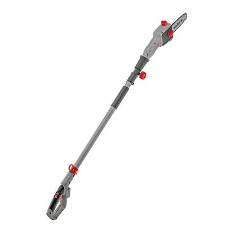
Ozito PXCPPS-018U User manual

EH-Art. No.: 34.108.16 I-No.: 11016
SPECIFICATIONS
Input: 18V
Bar Length: 200mm
Cutting Length Max.: 170mm
Chain Speed: 3.76m/s
Oil Tank Capacity: 125ml
Length: 1.83 - 2.77m
Weight (without battery:3.9kg
WHAT’S IN THE BOX
Pole
Battery & Charger sold separately
CORDLESS
POLE PRUNER
ORIGINAL INSTRUCTIONS
ozito-diy.co.uk
Guide Bar Cover
Pruner Head
Chain
Guide Bar
Rear Handle
Shoulder Strap
Auxiliary Handle
PXCPPS-018U
WARRANTY
0816
All of our products undergo strict quality checks to ensure that they reach you in perfect
condition. In the unlikely event that your device develops a fault, please contact our service
department at the address shown on this guarantee card. You can also contact us by
telephone using the customer service number shown. Please note the following terms under
which guarantee claims can be made:
1. These warranty terms regulate additional warranty services, which the manufacturer
mentioned below promises to buyers of its new products in addition to their statutory
guarantee claims are not affected by this guarantee. Our guarantee is free of charge to you.
2. The warranty services only covers defects due to material or manufacturing faults on
a product which you have bought from the manufacturer mentioned below are limited to
either the rectication of said defects on the product or the replacement of the product,
whichever we prefer.
Please note that our devices are not designed for use in commercial, trade or professional
applications. A guarantee contract will not be created if the device has been used by
commercial, trade or industrial business or has been exposed to similar stresses during the
guarantee period.
3. The following are not covered by our guarantee:
- Damage to the device caused by a failure to follow the assembly instructions or due to
incorrect installation, a failure to follow the operating instructions (for example connecting
it to an incorrect mains voltage or current type) or a failure to follow the maintenance and
safety instructions or by exposing the device to abnormal environmental conditions or by
lack of care and maintenance.
- Damage to the device caused by abuse or incorrect use (for example overloading the
device or the use or unapproved tools or accessories), ingress of foreign bodies into the
device (such as sand, stones or dust, transport damage), the use of force or damage caused
by external forces (for example by dropping it).
- Damage to the device or parts of the device caused by normal or natural wear or tear or by
normal use of the device.
4. Your Product is guaranteed for a period of 60 months from the original date of purchase
and is intended for DIY (Do It Yourself) use only. Lithium Ion batteries and chargers are
covered by a 12 month warranty. Warranty excludes consumable parts. Guarantee claims
should be submitted before the end of the guarantee period within two weeks of the defect
being noticed. No guarantee claims will be accepted after the end of the guarantee period.
The original guarantee period remains applicable to the device even if repairs are carried
out or parts are replaced. In such cases, the work performed or parts tted will not result
in an extension of the guarantee period, and no new guarantee will become active for the
work performed or parts tted. This also applies if an on-site service is used.
IN ORDER TO MAKE A CLAIM UNDER THIS WARRANTY YOU MUST RETURN THE PRODUCT TO
THE PLACE OF PURCHASE WITH YOUR REGISTER RECEIPT.
Please refer to the restrictions of this warranty concerning wearing parts, consumables and
missing parts as set out in the service information in these operating instructions.
CUSTOMER SERVICE HELPLINE
GB: 0151 294 4488
IRL: 1850 882711
Ozito-diy.co.uk
OZITO UK Unit 9 Stadium Court, Wirral International Business Park, Plantation Road, Bromborough, Wirral, CH62 3QG

KNOW YOUR PRODUCT SETUP & PREPARATION
1. ASSEMBLY
1. Chain
2. Guide Bar
3. Oil Cap
4. Side Cover
5. Pivoting Pruner Head Release
6. Telescopic Tube Lock
7. Main Tube
8. Auxiliary Handle
9. Shoulder Strap Holder
10. Assembly Nut
11. Pivoting Handle Release
12. Rear Handle
13. Chain Cover Lock
14. Chain Tension Adjustment Dial
15. Switch Lock
16. Auxiliary Handle Lever
17. Trigger Switch
18. Battery Seating
19. Mounting Attachment Lever
CORDLESS POLE PRUNER
1
2
3
4
5
6
7
8
ONLINE MANUAL
Scan this QR Code with your mobile device to take you to
the online manual.
15
16
10
11
12
13 14 9
17 18 19
BATTERY & CHARGER
(sold separately)
This tool is compatible with all battery and chargers from
the Ozito Power X Change Range.
For example: Batteries PXBP-200U (2Ah / 18V) &
PXBP-400U (4Ah / 18V). Charger: PXCG-030U (18V).
CAUTION: ENSURE THE TOOL IS OFF & THE BATTERY
REMOVED BEFORE PERFORMING ANY OF THE FOLLOWING
OPERATIONS.
Fitting Rear Handle
1. Push the rear handle fully
onto tube aligning the
internal prongs.
2. Screw tight with
the assembly nut.
Fitting Auxiliary Handle
1. Place the Auxiliary Handle onto
the mounting attachment.
2. Pass the bolt through the auxiliary handle and screw the lever to the end
of the bolt.
3. Select the most comfortable
position and close the lever
to lock the auxiliary handle in
position.

2. TENSIONING THE CHAIN
Note: The Lock Button will “CLICK” back to the left (original position) when
the pruner head is correctly secured in place.
3 - 4mm gap is
the ideal tension
Fitting Pruner Head
1. Align the pruner head and
the motor head so the
arrows on both coincide.
2. (a) Press the pruner head
against the motor head.
This will cause the lock
button to be pushed to the
right.
(b) Turn the pruner head
clockwise. The pruner head
will lock onto the motor
head and is then secured
in place.
Lock Button
a
b
Note: Only tighten the chain cover locking knob securely once the chain
tension has been adjusted (see: Tensioning the chain.)
CAUTION: THE CHAIN HAS SHARP EDGES. FOR YOUR
OWN SAFETY, PLEASE WEAR WORK GLOVES.
IMPORTANT: IF THE CHAIN IS INSTALLED BACKWARDS
(CHAIN CUTTERS ARE FACING IN THE OPPOSITE
DIRECTION OF ROTATION) THE POLE PRUNER WILL
VIBRATE EXCESSIVELY AND NOT CUT.
Fitting Guide Bar & Chain
1. Loosen the
chain cover
lock and
remove the
side cover.
2. Place the chain in the groove
of the guide bar as shown.
Refer to the image printed on
the guide bar that indicates
the direction that the chain
should face.
Sprocket
3. Place onto the mount,
ensuring that the chain sits
around the chain sprocket.
4 Re-mount and nger-tighten
the side cover with the chain
cover lock.
1. Loosen the chain
cover lock. Do not
remove the side
cover.
CAUTION: IF YOU TRY TO ROTATE THE CHAIN TENSIONING
ADJUSTMENT DIAL WHILST THE CHAIN COVER LOCK IS
TIGHT, IT WILL RESULT IN THE CHAIN NOT LOOSENING
AND POSSIBLE DAMAGE TO THE MECHANISM.
2. Adjust the chain tension with
the chain tensioning adjustment
dial. Turning the dial CLOCKWISE
increases the chain tension,
turning it COUNTER-CLOCKWISE
decreases the chain tension.
For the correct chain tension, rmly
pull up on the chain at the middle
of the top of the exposed guide bar.
When the chain is pulled up to its
highest point, the bottom tip of the
links should only just stay in the track
[middle of the guide bar]
CAUTION: THE CHAIN HAS SHARP EDGES. FOR YOUR
OWN SAFETY, PLEASE WEAR WORK GLOVES.
3. After the chain has been
accurately tensioned, lock the
guide bar in place with the
chain cover locking knob.
Note: Proper tension of the chain is extremely important and must be
checked before starting, as well as during any cutting operation.
Taking the time to make adjustments to the chain will result in
improved cutting performance and prolonged chain life.

3. OIL 4. PREPARATION
Adjusting the Rear Handle
Note: Chain bar oil may leak if the tool is left for long periods. This is
normal. If the tool is to be left unused for an extended time, drain the
oil from the tool. Rell before use.
Adjusting the telescope length
1. To unlock the telescopic tube lock, twist it in
a clockwise direction while pointing the chain
away from the user.
2. Pull out the telescopic tubes to suit the required working height.
1. Press the two pivoting
handle releases, one
each side and adjust
the angle of the handle
up or down to any of 4
positions.
Note: The locking and unlocking
directions are indicated on
the locking collar.
3. To lock in the desired position, twist the telescopic tube lock in a counter-
clockwise direction.
Adjusting the Auxiliary Handle
a
b
a
b
a
b
a
b
1. (a) Open the handle lever and
set the required (b) tilt of the
auxiliary handle, close to lock
into position.
2. (a) Open the mounting bracket
lever and (b) slide the auxiliary
handle into the required position,
close to lock into position.
4. To check the lubricating system, switch on the pole pruner and hold it
with the guide bar and chain above some light coloured paper such as
newspaper. A steadily increasing stain caused by oil spray shows the
lubricating system is working.
2. Fill the tank with chain bar oil.
The capacity of the chain oil
tank is 125ml. Do not over ll.
WARNING!: NEVER START WORK UNLESS THE
CHAIN AND BAR ARE LUBRICATED
1. Remove the chain bar oil cap.
3. Ret cap and clean any oil spillage.
4. Always ll oil tank when the oil
level is below the minimum mark
on the oil level window.
IMPORTANT: ONLY USE OIL THAT IS EXPRESSLY LABELLED
“CHAIN BAR OIL”.
min
max
min
min
max
min
min
max
min
min
max
min

PXCPPS-018U
5. INSERTING & REMOVING THE BATTERY
1. Align the ribs of the battery with
the recess below the handle
Removing a Battery from the Pole Pruner
2. Slide the battery in so
that it clicks into place.
1. Press and hold the battery
release tab to release the
battery.
2. Slide the battery out.
Installing a Battery into the Pole Pruner
2. Wear the shoulder strap
so that it lies over the left
shoulder.
1. Fasten to the shoulder strap
holder on the main tube.
Adjusting the Pruner Head
1. Press the two pivoting
head releases, one each
side and adjust the
angle of the pruner head
up or down to any of 7
positions.
Lock Button
Lock Button
2. The pruner head will lock
onto the motor head and is
then secured in place.
1. Pull the lock button to the
right then rotate the pruner
head 90ºclockwise
Note: The Lock Button will “CLICK” back to the left (original position) when
the pruner head is correctly secured in place.
•Adjusting the Pruner Head 90º
Attaching the Shoulder Strap
•Pivoting the Pruner Head
Note: Keep the pruner head
pressed against the
motor head when
rotating.

6. SWITCHING ON/OFF
OPERATION
a
b
a
Switching On
1. Hold the pruner rmly with both hands.
a
b
a
2. Slide the switch lock (a) to the
front with your thumb and hold,
then squeeze the trigger switch
(b).
a
b
a
3. The chain will now be running
ready to make a cut. Release the
switch lock (a).
Switching Off
a
b
a
3. Release the trigger switch. The
chain and motor will quickly
stop.
APLICATIONS
•Limbing is the process of removing
the branches from a fallen tree.
Check the direction in which a branch
will bend before cutting it. Always
cut on the opposite side to the
bending direction so that the guide
bar is not pinched in the cut. For
large limbs that cannot be removed in one cut, make an initial cut from
the bent side and nish by sawing from the opposite direction. Do not
remove limbs that are supporting the fallen tree on the ground until the
tree has been cut into lengths.
1
2
Pruning
•Pruning is the removal of a limb or
branch from a standing tree.
WARNING!:IF THE CHAIN COMES IN CONTACT WITH
A HARD OBJECT, VISUALLY INSPECT THE CHAIN
& BAR FOR DAMAGE. IF THE CHAIN OR BAR IS
DAMAGED, DO NOT CONTINUE TO OPERATE THE
POLE PRUNER.
1
2
Limbing
WARNING!: NEVER USE THE POLE PRUNER WHEN
STANDING ON A LADDER OR UNEVEN GROUND. DO
NOT OVERREACH. ALWAYS USE BOTH HANDS TO
HOLD THE POLE PRUNER.
CAUTION: ALWAYS USE THE BUCKING SPIKES WHEN
PERFORMING CUTS WITH THE POLE PRUNER TO AVOID
KICKBACK (REFER TO OPERATION SECTION OF MANUAL).
CAUTION: ENSURE APPROPRIATE CARE IS TAKEN WHEN
CUTTING ABOVE SHOULDER HEIGHT.
Sawing Techniques
•When removing branches, hold
the pruner at an angle ranging
from a maximum 60° to horizontal
in order to avoid being struck by a
falling branch.
•At the end of the cut, the
weight of the pruner suddenly
increases for the user, because
it is no longer supported on
the branch. There is the risk of
losing control of the pruner.
•Saw off the lower branches on the
tree rst. By doing so, it is easier
for the cut branches to fall to the
ground.
•Only pull the pruner out of the
cut with the chain running. By
doing so, you can prevent it
from getting jammed.
•Do not saw with the tip of the
guide bar. This could lead to
kick back and possible injury.
60°

Wear safety goggles, a face guard
and ear protection.
Read the directions for use
before operating the equipment.
Protect the equipment from
rain and damp.
Wear safety gloves
Watch out for falling and
catapulting parts.
Electric shock can cause fatal injury. Keep a distance of at least 10 m
from power cables.
Wear sturdy, non-slip
footwear.
Alternating current
Hertz
Watts
Diameter
Milliamperes
Warning!
Maximum cutting length of
the pole-mounted pruner.
Direction of the chain
movement and teeth of
the pole-mounted pruner.
Keep your distance.
Maintaining the guide bar
1. Remove any sawdust from the guide bar, including the groove.
Oil and sawdust combine and emit a burning smell during operation if the blade is
not regularly cleaned.
2. Make sure that the oil port is not clogged. Grease the nose sprocket at the tip of the
guide bar.
3. Check for oil leakage and loose fastenings, especially those securing the handles
and the guide bar.
4. Reverse the guide bar every 8 working hours to ensure uniform wear. Check the
guide rails frequently and if necessary remove burrs and square up the rails using a
at le.
Chain Sharpening
Chain File: 3.96mm (5/32”)
Chain Pitch: 9.53mm (3/8”)
Chain Gauge: 1.3mm (0.050”)
Sharpen the chain regularly to maintain
optimum performance of the saw. Signs of a
dull chain are:
• Thesawdustbecomespowder-like
• Extraforceisrequiredtoexecuteacut
• Thecutdoesnottrackinastraightline
• Increasedvibration
Sharpen each cutter using a round 3.96mm (5/32”) chain le. Keep the le level with
the top plate of the tooth. Always use outward strokes and maintain a 30° angle
between the chain and le. After sharpening, the cutters must all have the same width
and length.
After every 3–4 uses get an authorised repair centre to professionally sharpen your
chain. They have the special tools necessary to ensure the correct cutting angles and
depths.
LEFT HAND
CUTTERS
STRAIGHT
ARM
POSITION
CHAIN
LINE
RIGHT HAND
CUTTERS
30°
30°
MAINTENANCE
SPARE PARTS
WARNING: BEFORE CLEANING YOUR POLE PRUNER,
CARRYING OUT ANY MAINTENANCE PROCEDURE
OR TROUBLESHOOTING, MAKE SURE THAT THE
MOTOR IS OFF AND THE BATTERY REMOVED TO PREVENT
ACCIDENTAL STARTING.
CAUTION: ALWAYS WEAR GLOVES WHEN HANDLING
THE CHAIN AS IT IS VERY SHARP AND CAN CUT YOU
WHEN IT IS NOT MOVING.
Spare parts can be ordered from the Special Orders Desk at your local
Bunnings Warehouse or Homebase store.
For further information, or any parts visit
www.ozito-diy.co.uk or contact Ozito Customer Service:
Great Britain: 0151 294 4488
Ireland: 1850 882711
E-mail: enquires@ozito-diy.co.uk
Pole-mounted pruner (chainsaw with telescopic handle)
The chain saw mounting kit is allowed to be used only on the supplied motor head.
The chainsaw with telescopic handle is designed for lopping off tree branches. It is not
suitable for extensive sawing work, felling trees or sawing any materials other than
wood.
The equipment is to be used only for its prescribed purpose. Any other use is deemed to
be a case of misuse. The user / operator and not the manufacturer will be liable for any
damage or injuries of any kind caused as a result of this.
Please note that our equipment has not been designed for use in commercial, trade or
industrial applications. Our warranty will be voided if the machine is used in commercial,
trade or industrial businesses or for equivalent purposes.
PROPER USE
DESCRIPTION OF SYMBOLS
Fault Possible cause Remedy
The equipment does
not work
- Battery empty
- Battery is not correctly inserted
- Charge battery
- Remove battery and insert again
Equipment operates
intermittently
- Loose connection (external)
- Loose connection (internal)
- ON/OFF switch defective
- Consult a specialist workshop.
Saw chain is dry - No oil in the tank
- Vent in the oil tank cap is blocked
- Oil outlet is blocked
- Top up with oil
- Clean the oil tank cap
- Clear the oil outlet
Chain/guide bar is hot - No oil in the tank
- Vent in the oil tank cap is blocked
- Oil outlet is blocked
- Chain is blunt
- Chain is overtensioned
- Top up with oil
- Clean the oil tank cap
- Clear the oil outlet
- Re-sharpen or replace the chain
- Check the chain tension
Chainsaw judders,
vibrates or does not saw
properly
- Chain is undertensioned
- Chain is blunt
- Chain is worn
- Saw teeth point in the wrong
direction
- Adjust the chain tension
- Re-sharpen or replace the chain
- Replace the chain
- Re t the chain with the teeth facing
in the correct direction
The table below contains a list of fault symptoms and explains what you can do
to remedy the problem if your equipment fails to work properly. If the problem still
persists after working through the list, please contact your nearest service workshop.
Troubleshooting Guide

ADDITIONAL SAFETY INSTRUCTIONS
ADDITIONAL INFORMATION
Mayr/Product-ManagementWeichselgartner/General-Manager
- 135 -
explains the following conformity according to EU directives and norms for
the following product
Cordless Pole Pruner PXCPPS-018U (Ozito)
2014/29/EU
2005/32/EC_2009/125/EC
2014/35/EU
2006/28/EC
X2014/30/EU
2014/32/EU
2014/53/EC
2014/68/EU
90/396/EC_2009/142/EC
89/686/EC_96/58/EC
X2011/65/EU
X2006/42/EC
XAnnex IV
Notied Body: TÜV Rheinland LGA Products Gmbh - Tillystraße 2 - 90431 Nürnberg
Germany
Notied Body No.: 0197
Reg. No.: BM 50365795 0001
X2000/14/EC_2005/88/EC (Outdoor)
XAnnex V
Annex VI
Noise: measured LWA = 98,23 dB (A); guaranteed LWA = 102 dB (A)
P = KW; L/Ø = cm
Notied Body: TÜV Rheinland
2012/46/EU (Schadsto - Abgas)
Emission No.:
Standard references: EN 60745-1:2009; EN ISO 12100:2010; EN ISO 11680-1:2011;
EN 55014-1:2006+A1+A2; EN 55014-2:2015
Landau/Isar, den 28.09.2016
First CE: 16 Archive-File/Record: NAPR015300
Art.-No.: 43.108.16 I.-No.: 11016 Documents registrar: R. Gehard
Subject to change without notice Wiesenweg 22, D-94405 Landau/Isar
ISC GmbH · Eschenstraße 6 · D-94405 Landau/Isar
EG_Erkl_PXCPPS_018U.indd 135 08.12.2016 08:39:19
Danger!
Sound and vibration
Sound and vibration values were measured in accordance with ISO 22868.
LpA sound pressure level ................... 81.05 dB(A)
KpA uncertainty .............................................3 dB
LWA sound power level measured .. 98.23 dB(A)
KWA uncertainty .............................................3 dB
LWA sound power level guaranteed ... 102 dB(A)
Wear ear-muffs.
The impact of noise can cause damage to hearing.
Total vibration values (vector sum of three directions) determined in accordance with ISO 22867.
Handle under load
Vibration emission value ah = 0.947 m/s2
K uncertainty = 1.5 m/s2
The speci ed vibration value was established in accordance with a standardized testing method. It may
change according to how the electric equipment is used and may exceed the speci ed value in exceptional
circumstances.
The speci ed vibration value can be used to compare the equipment with other electric power tools.
The specied vibration value can be used for initial assessment of a harmful effect.
Keep the noise emissions and vibrations to a minimum.
• Only use appliances which are in perfect working order.
• Service and clean the appliance regularly.
• Adapt your working style to suit the appliance.
• Do not overload the appliance.
• Have the appliance serviced whenever necessary.
• Switch the appliance off when it is not in use.
• Wear protective gloves.
We pay a great deal of attention to the design of every battery pack to ensure that
we supply you with batteries which feature maximum power density, durability and
safety. The battery cells have a wide range of safety devices. Each individual cell is
initially formatted and its electrical characteristic curves are recorded. These data
are then used exclusively to be able to assemble the best possible battery packs.
Despite all the safety precautions, caution must always be exercised when
handling batteries. The following points must be obeyed at all times to ensure
safe use.
Safe use can only be guaranteed if undamaged cells are used. Incorrect
handling can cause cell damage.
Important: Analyses con rm that incorrect use and poor care are the main causes
of the damage caused by high performance batteries.
For EU countries only
Never place any electric power tools in your household refuse.
To comply with European Directive 2012/19/EC concerning old electric and electronic
equipment and its implementation in national laws, old electric power tools have to be
separated from other waste and disposed of in an environment-friendly fashion, e.g. by
taking to a recycling depot.
Recycling alternative to the return request:
As an alternative to returning the equipment to the manufacturer, the owner of the electrical
equipment must make sure that the equipment is properly disposed of if he no longer wants
to keep the equipment. The old equipment can be returned to a suitable collection point that
will dispose of the equipment in accordance with the national recycling and waste disposal
regulations. This does not apply to any accessories or aids without electrical components
supplied with the old equipment.
The reprinting or reproduction by any other means, in whole or in part, of documentation and
papers accompanying products is permitted only with the express consent of the iSC GmbH.
Subject to technical changes
This consignment contains lithium-ion batteries.
In accordance with special provision 188 this consignment is not subject to the ADR
regulations. Handle with care. Danger of ignition in case of damage to the consignment
package. If the consignment package is damaged: Check and if necessary repackage. For
further information contact: 0049 1807 10 20 20 66 ( xed network 14 ct/min, mobile phone
max. 42 ct/min) Outside Germany charges will apply instead for a regular call to a landline
number in Germany.
Table of contents
Other Ozito Pole Saw manuals
Popular Pole Saw manuals by other brands

FLORABEST
FLORABEST FALH 40-Li A1 Operation and safety notes

SereneLife
SereneLife PSPR170 user manual

Ikra
Ikra ITHK 800 operating instructions

Makita
Makita UA003G instruction manual

Grizzly Tools
Grizzly Tools AKS 2040-21 T Lion Set Translation of the original instructions for use

Greencut
Greencut PP560L instruction manual

Wolf Garten
Wolf Garten Li-ION POWER PSA 700 Original operating instructions

Remington
Remington BRANCH WIZARD 111409-01 owner's manual

Black & Decker
Black & Decker GPC1800L Original instructions

Tanaka
Tanaka TPS-260PF Illustrated parts manual

EINHELL
EINHELL 34.082.20 Original operating instructions

EINHELL
EINHELL GE-LC 18 Li T Original operating instructions