P-Tronic 40P User manual

Instruction Manual GB
P-Tronic 40P - P-Tronic 70 - P-Tronic 100
This manual is completed by the “CE Operating and service maual” Edition Rev.20130304
P-Tronic 40P - 70 - 100

GB
English
Instruction Manual P-Tronic 40P - 70 - 100
INDEX
Chap. Description Page
Introduction
1. Conformity declaration 1
1.1 RAEE Norm 2
1.2 safety precautions 2
1.3 thermal limits (en 60974-1) 2
2. Safety device 3
2.1 Safety device signal 3
3 Explanation of technical specication 3
3.1 Technical specication table 4
4 Start-up and use 4
4.1 Main supply connection 4
5. P-TRONIC 40P general description 5
5.1 P-TRONIC 40P front pannel description 5
6 P-TRONIC 40P optional kit air reducer 5
6.1 P-TRONIC 40P assembling of the optional
pressure reducer 5
6.2 P-TRONIC 40P use of the equipement 6
7. P-TRONIC 70 general description 7
7.1 P-TRONIC 70 installation 7
7.2 P-TRONIC 70 front pannel description 7
8. P-TRONIC 70 standard stand o- grating
- gouging 7
8.1 P-TRONIC 70 standard stand o 8
8.2 P-TRONIC 70 grating 8
8.3 P-TRONIC 70 gouging 8
Chap. Description Page
9. P-TRONIC 70 use of the equipement 9
10. P-TRONIC 100 general description 9
10.1 P-TRONIC 100 Installation 9
10.2 P-TRONIC 100 front panel description 9
11. P-TRONIC 100 standard stand o –
grating – gouging 10
11.1 P-TRONIC 100 standard Stand O
in Solid Cutting 11
11.2 P-TRONIC 100 standard Solid Cutting 12
11.3 P-TRONIC 100 grating 12
11.4 P-TRONIC 100 gouging 13
12. P-TRONIC 100 use of the equipement 13
13. Complete torch TER - 80 direct 14
14. Complete torch TER - 80 15
15. Complete torch TER - 100 16
16. Machanized applications
complete torch TER - 100M 17
17. P-TRONIC 40P spare Parts 18
18. P-TRONIC 40P electric wiring diagram 19
19. P-TRONIC 70 spare Parts 20
20. P-TRONIC 70 electric wiring diagram 21
21. P-TRONIC 100 spare Parts 22
22. P-TRONIC 100 electric wiring diagram 23

GB
English
Instruction Manual P-Tronic 40P - 70 - 100
WARNING
IMPORTANT: BEFORE STARTING THE EQUIPMENT, READ THE CONTENTS OF THIS MANUAL, WHICH MUST BE STORED IN A PLACE FAMILIAR TO ALL
USERS FOR THE ENTIRE OPERATIVE LIFE-SPAN OF THE MACHINE.THIS EQUIPMENT MUST BE USED SOLELY FOR CUTTING OPERATIONS.
INTRODUCTION
To obtain the best performance from the machine and ensure the longest possible life of all its components you must careully follow the instructions for use and
maintenance detailed in this manual. In the interest of our customers we suggest any maintenance or repair of the equipment is made by qualied personnel.
All our products are subject to a constant development. We are therefore constrained to reserve the right to make any necessary or useful changes in design and
equipment.
ROUTINE MAINTENANCE
Prevent metal powder from accumulating inside the equipment. Disconnect the power supply before every operation ! Carry out the following periodic controls on
the power source:
• Clean the power source inside by means of low-pressure
compressed air and soft bristel brushes.
• Check the electric connections and all the connection cables.
For the use and maintenance of the pressure reducers, consult the specic manuals.
1. Conformity declaration
The machines descripted in this manual, P-TRONIC 40P, P-TRONIC 70, P-TRONIC 100, must be used solely for professional purposes in an industrial environment
and they are manufactured in compliance with the instructions contained in the harmonized standard EN50199 (electromagnetic compatibility) and EN60974-1.
IN CASE OF BAD OPERATION YOU DEMAND THE ATTENDANCE OF QUALIFIED STAFF.
GB
English
Instruction Manual P-Tronic 40P - 70 - 100
1. Conformity declaration
TER SRL – 36030 Caldogno (VI) – Italy
declares that the machines descripted in this manual must be use solely for professional purposes
in an industrial environment and they are manufactured in compliance with the instructions con-
tained in the harmonized standard:
2006/95/CE (LDV) – 2004/108/CE (EMC) – 2002/95 (RoHs)
and with the instructions contained in the harmonized standard,
if applicable:
EN 60974-1 EN 60974-2 EN 60974-3 EN 60974-5 EN 60974-7
EN 60974-10 EN 60974-12
Date 30/01/2012 Maurizio Terzo
General Manager
IN CASE OF BAD OPERATION YOU DEMAND THE ATTENDANCE OF QUALIFIED STAFF
- 1 -
The equipment don’t compiles with EN/ IEC 61000-3-12.
The installer or the user must be sure that it can be connected to the public low voltage power line,
if necessary, in consultation with the network distributor.

GB
English
Instruction Manual P-Tronic 40P - 70 - 100
1.1 RAEE Norm
The symbol on the product or on its packaging indicates that this product may not
be treated as household waste. Instead it shall be handed over to the ap-
plicable
collection point for the recycling of electrical and electronic equipment. By
ensuring
this product is disposed of correctly, you will help prevent potential negative
consequencesf or the environment and human health, which could otherwise be
caused by inappropiate waste handling of this product. For more detailed infor-
mation about recycling of this product, please contact your local city oce, your
household waste disposal service or the shop where you purchased the product.
1.2 SAFETY PRECAUTIONS
WELDING AND ARC CUTTING CAN BE HARMFUL TO YOURSELF AND
OTHERS. The user must therefore be educated against the hazards, summarized
below, deriving from welding operations.
1.3 THERMAL LIMITS (EN 60974-1)
a) The use of a cutting equipment is normally not continuous, since there are actual
work periods (cutting time) and pause periods (positioning work pieces etc.).
This cutting unit has been manufactured to supply the maximum nominal current
I2 in complete safety for a working time of ED% of the total time. The standards in
force, state a work period of 10 minutes. The maximum duty cycle is the ED of the
data check. If you exceed the recommended work/pause periods, you will cause
overheating of the machine components that could put it out of order.
A thermal protection device is then activated, shown by the turning on of LED lo-
cated on the front Panel.
After a few minutes this device automatically turns on the machine, the LED goes
o and the machine is ready for use again.
b) These machine is built according to IP 21 CS protection standards.
ELECTRIC SHOCK – May be fatal.
Install and earth the welding machine according to the applicable regu-
lations. Do not touch live electrical parts or eletrodes with bare skin,
gloves or wet clothing. Isolate yourselves from both the earth and the
workpiece. Make sure your working position is safe.
FUME AND GASES – May be hazardous to your health.
Keep your head away from fumes.
Work in the presence of adequate ventilation, and use ventilators
around the arc to prevent gases from forming in the work area.
ARC RAYS – May injure the eyes and burn the skin.
Protect yuor eyes with welding masks tted with ltered lenses, and
protect your body with appropiate safety garments.
Protect others by installing adequate shields or curtains.
RISK OF FIRE AND BURNS
Sparks (sprays) may cause res and burn the skin; you should
therefore make sure there are no ammable materials in the area, and
wear appropriate protective garments.
NOISE
This machine does not directly produce noise exceeding 80dB. The
plasma cutting/welding procedure may produce noise levels beyond
said limit; users must therefore implement all precautions required by law.
PACEMAKERS
The magnetic fields created by high currents may affect the operation of pace-
makers. Wearers of vital electronic equipment (pacemakers) should consult
their physician before beginning any arc welding, cutting, gouging or
spotwelding operations.
EXPLOSIONS
Do not cut in the vicinity of containers under pressure, or in the
presence of explosive dust, gases or fumes. All cylinders and pressu-
re regulators used in cutting operation should be handled with care.
PLASMA ARC can injure.
Keep your body away from nozzle and pla-
sma arc. Operate the pilot arc with caution.
The pilot arc is capable of burning the ope-
rator, others even piecing safety clothing.
- 2 -
GB
English
Instruction Manual P-Tronic 40P - 70 - 100
Led P-Tronic 70 - 100
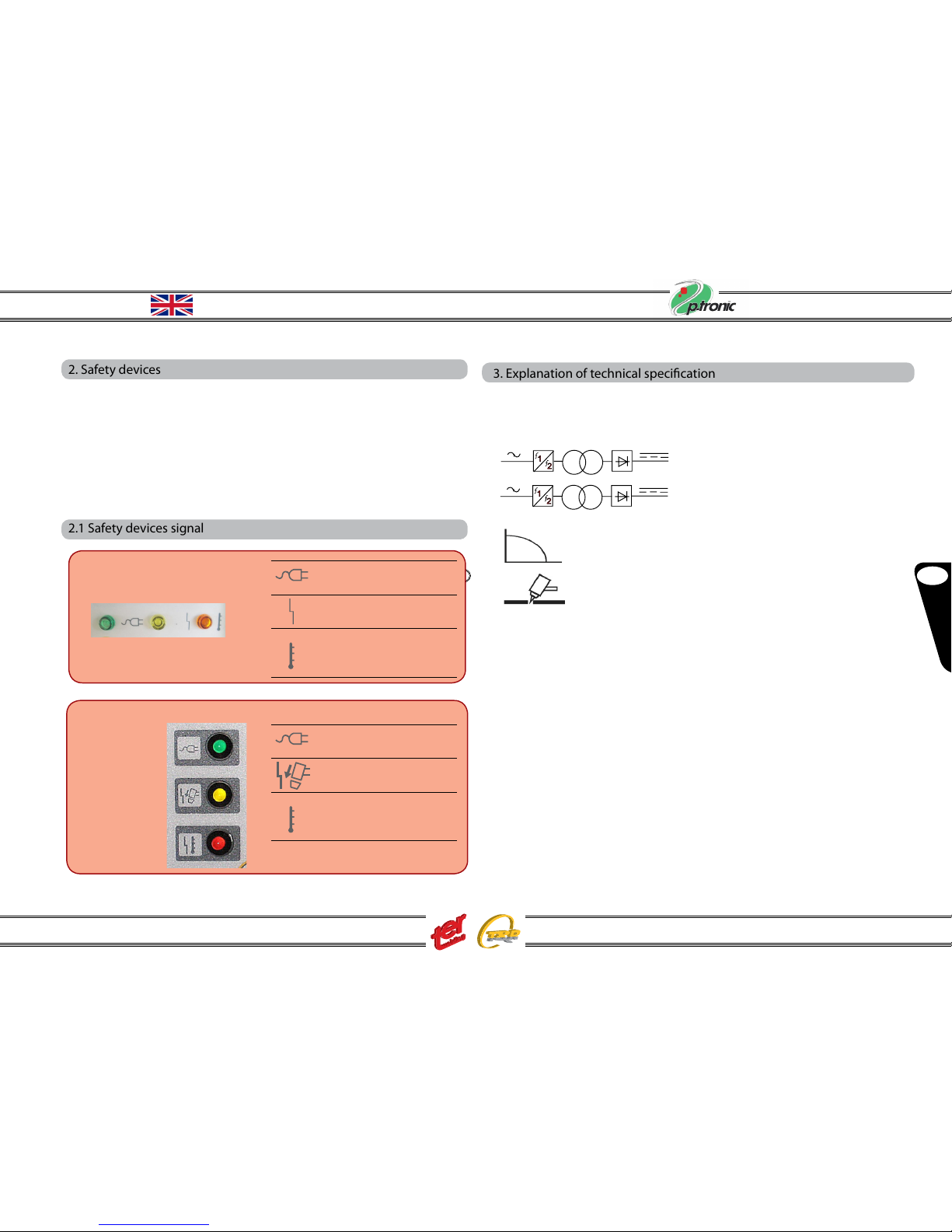
2. Safety devices
This system comes equipped with the following safety devices: (see table 1 )
Overload cut out: to avoid overload while cutting.
Pneumatic: located on the torch inlet to prevent low air
pressure.
Electrical:
* In the event of the main voltage is too low or too high.
* In the event of torch maintenance with main power on. In this event all cutting
function are prevent
2.1 Safety devices signal
Led P-Tronic 40P
Green Led ON/OFF
Allarm when torch
nozzle is loose
Alarm when over load,
over current supply
voltage outside limits
Green Led ON/OFF
Alarm when torch
nozzle is loose
Allarm when over load,
over current, supply
voltage outside limits
3. Explanation of technical specication
EN 60974.1 The machine has been built according to this European standards
EN 60974.10
N............ Serial number. Always indicate this for any request
Single phase static transformer rectier
frequency converter, inverter.
Three phase static transformer rectier
frequency converter, inverter.
Drooping characteristic.
Suitable for plasma cutting.
TORCH TYPE.. Type of torch that may be used with this machine.
U0 ................... Secondary open-circuit voltage Peak value.
X%................... Percentage duty cycle.
The duty cycle expresses the percentage of 10 minutes for
which the machine may work at a certain current I2 and
voltage U2 without overheating.
I2...................... Cutting current.
U2.................... Secondary voltage at cutting current I2.
This voltage in measured when cutting with the gas nozzle
in contact with the work piece.If this distance increases,
the cutting voltage also increases and the duty cycle X%
may drop.
U1.................... Main supply voltage
1/3~50/60 Hz... Single phase 50/60 Hz power supply, treephase 50/60Hz
I1...................... Primary supply current at the corrispondind cutting current
I2 and cutting voltage U2 .
IP21S............... Housing protection rating.
3
3
1
- 3 -
GB
English
Instruction Manual P-Tronic 40P - 70 - 100
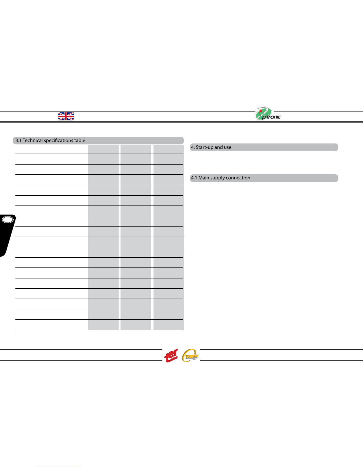
3.1 Technical specications table
Technical data P-Tronic 40P P-Tronic 70 PTronic 100
Code V0042AA VOO82AA V0059AA
Main supply (-10%/+15%) VAC 1Ph x 230V 3Ph x 400V 3Ph x 400V
Frequency Hz 50/60 50/60 50/60
Main power (60%) KVA 6 / ED50% 11 16
Open current voltage V0 V 260 280 310
Current range I2 A 20 ÷ 40 20 ÷ 70 20 ÷ 100
Cutting current I2 (X%) A 40A + ED50% -------- ----------
Cutting current I2 (60%) A 36 70 100
Cutting current I2 (100%) A 25 55 75
Recommended cutting capc. mm 12 18 22
Maximum cutting capacity mm 20 25 30
Severence cutting capacity mm 30 35 40
Gas pressure (torch 6 m.). bar 4,5 ÷ 5 5,5 ÷ 6,0 5,5 ÷ 6,0
Insulation class F F F
Protection degree IP 21S 21S 23
Dimensions mm 310x180x480 360x350x630 610x340x680
Weight Kg 9 25 39
4. Start-up and use
The machine must be installed by qualied personnel. All connections must be
made in compliance with current safety standards and full observance of
safety regulations.
4.1 Main supply connection
Connect the power cord A: the yellow-green cable wire must be connected to an
ecient grounding socket on the system. The remaining wires must be
connected to the power supply line by means of a switch placed as close as pos-
sible to the cutting area, to allow it to be shut o quickly in case of emergency.
The capacity of the cut-out switch or fuses installed in series with the switch must
be equal to the current I1 absorbed by the machine. The absorbed current I1 may
be determined by reading the technical specications shown on the machine
under the available supply voltage U1 . Any extension cords must be sized
appropriately for the absorbed current I1.
- 4 -

GB
English
Instruction Manual P-Tronic 40P - 70 - 100
5. General description
This apparatus is a constant direct current (DC) generator, designed to cut
electro conductive materials (metals and alloys) by a plasma arc process. The
plasma gas is generated by using compressed air.
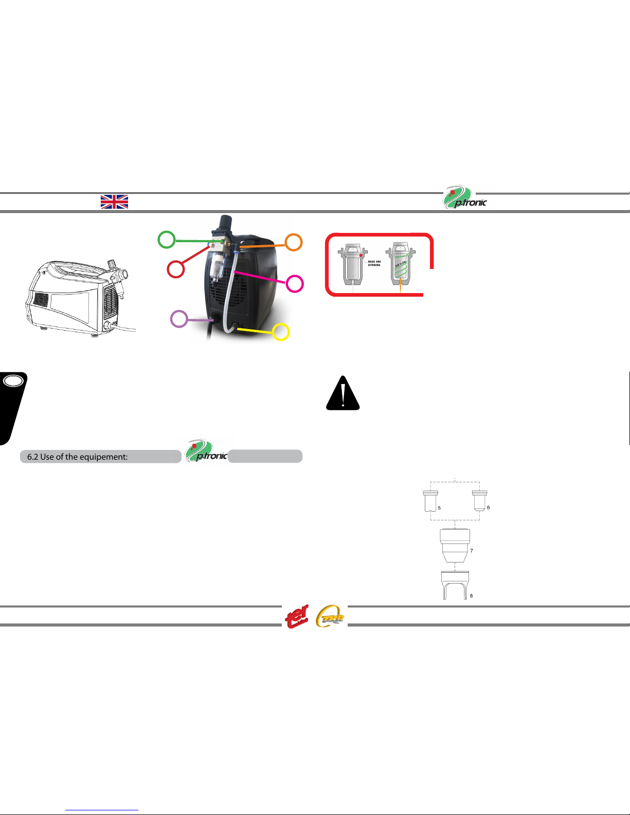
5.1 Front panel description P-Tronic 40 model
56
4
7
3
2
1
1 Output current knob: it sets the output cutting current
2 ON/OFF switch: it turns the apparatus on and o.
3 Manometer: it shows the air pressure (bar) during the cut – using the gas pressure
reducer knob, it must be positioned at 4,5 – 5,0 bars
4 Earth clamp socket
5 ON/OFF led: it lights up when machine is ON
6 Safety led : it lights up when the torch safety circuit is activated
7 Thermal and over-voltage led: it lights up in case of thermal problems or wrong volta
ge supply
8 Torch output
WARNING: the generator is equipped with a TER PT-80 plasma torch,
cod. ZO132AA 6 mt long. This torch has to be considered as integral
part of the generator and its functioning and safety are guaranteed
only with the original torch. For any spare parts refer to the appendix
list. The torch is equipped with a safety circuit which prevents any
accidental contacts with conductive elements: the generator does
not work if the safety circuit is activated.
Switch always the machine OFF when working on the torch.
6. Optional kit - Air reducer P-Tronic 40
The P-Tronic 40 generator is equipped with a manometer but the air pressure reg-
ulation must be set with a pressure reducer that has to be connected externally.
The optional kit “Pressure reducer P-Tronic 40” cod. Z0157AA consists in a pres-
sure reducer and relevant xing hanger.
6.1 Assembling of the optional Pressure reducer P-Tronic 40 kit
Proceed as shown in the pictures:
Step 1:
Insert the hanger on the handle
Step 2:
Rotate the hanger of about 90°
until the closing “click”
- 5 -
P-Tronic 40P
P-Tronic 40P
P-TRONIC 40P
8
GB
English
Instruction Manual P-Tronic 40P - 70 - 100
Step 4:
The reducer has an “IN” nipple that has
to be connected to the compressed air
net and an “OUT” nipple: provide an 8x6
teon tube of about 30 cm to link the out-
put nipple “OUT” with the machine air in-
put nipple positioned on the back of the
machine.
Step 3:
Put the hanger on the handle back
side and x the reducer using the
proper ring nut
23
5
1
4
6
IN nipple
Supply Cable
Air Input
Filter/Reducer OUT nipple
Teon
tube
E) Press the torch trigger: the pilot arc stricks, becoming cutting arc as
soon as you will place the torch on the work
piece. The P-TRONIC 40 generator does
not work with high-frequency arc ignition:
it uses the no HF technology with BACK
STRIKING system. The torch can work only
if the generator is connected to the com-
pressed air plant
F) The pilot arc stops automatically after about 5 seconds if you do not place
the torch on the work piece
G) Check the manometer value and adjust eventually the air pressure
H) Once the cutting process is terminated release the torch trigger: the air
ow will continue to allow the cooling down of the torch
Warning: never aim the plasma jet towards people or
foreign objects !
6.2 Use of the equipement:
A) Connect the earth clamp cable to the work piece
B) Connect the machine to the power supply net and turn ON the power
switch (position 2. page. 5); the ON/OFF led (position 5 page. 5) light on
C) Check the air pressure on the manometer as indicated in the previous
paragraph
D) Set the current value with the knob (1st position fig. pag. 5) according to
the work piece tickness
According to the cutting type and mode, the torch must be equipped with suitable
spare parts. The P-Tronic 40 generator enables either the contact or stand-o
cutting.If you have to make a precision cut on sheet metal and when the spacer (8)
cannot be used, we recommand the Tip 0,9 (5) code Z0050AA. In case of spacer/
stand o cutting, use the Tip 1,0 (6) code Z0051AA.
- 6 -
P-Tronic 40P

GB
English
Instruction Manual P-Tronic 40P - 70 - 100
P-TRONIC 70
7. PLASMA P-TRONIC 70 General description
This apparatus is a constant direct current (DC) generator, designed to cut
electro conductive materials (metals and alloys) by a plasma arc process.
The plasma gas is generated by using compressed air.
7.1 Installation
The machine needs to be supplied with clean and dry air. Set the air pressure
at 5,5-6,0 bars and make sure it does not change during the cut; a bad and/or
uncorrect air supply generates problems on the cutting quality and the torch
might be damaged too.
1 Output current knob: it sets the output cutting current
2 Manometer: it shows the air pressure (bar) during the cut
3 Cutting mode selector: grating, standard stand o, gouging
4 Earth clamp socket
5 pressure regulator knob
6 remote control socket
7 torch connector
8 ON/OFF switch
9 Monitor Led (see page 2)
8
3
4
9
2
1
5
7
6
- 7 -
7.2 Front panel description P-Tronic 70 model
The generator can work in three dierent modes:
8. STANDARD STAND OFF – GRATING – GOUGING
SOLID CUT GOUGING APPLICATION
GRATING CUT
WARNING: the generator is equipped with a TER PT-80 plasma torch, cod
Z0133AA 6 mt long. This torch has to be considered as integral part of the
generator and its functioning and safety are guaranteed only with the origi-
nal torch. For any spare parts refer to the appendix list.
The torch is equipped with a safety circuit which prevents any accidental
contacts with conductive elements: the generator does not work if the safety
circuit is activated.
Switch always the machine OFF when working on the torch.
P-Tronic 70
P-Tronic 70
P-Tronic 70
P-Tronic 70
P-Tronic 70
P-TRONIC 70

GB
English
Instruction Manual P-Tronic 40P - 70 - 100
In certain applications the contact cutting may be required even with currents over the 40A (ex. high
cutting speed on thin metal sheet or on high ticks where a high cutting precision is required).
Inthoseapplications,use the spare parts described in the picture:
pos (9) Currents until 50A Tip diam 1,0 cod Z0145AA
pos (9) Currents until 70A Tip diam 1,1 cod Z0146AA
pos (9) Currents over 70A Tip diam 1,2 cod Z0147AA
pos 11 Use Shield cup body cod Z0089AA
pos 12 Use Shield cup hand cod Z0140AA
NOTE: the spare parts are the same even if a straight automatic torch is used
- 8 -
8.1 Standard Stand O
This is the typical and most commun cutting type; you can adjust the current from a minimum
of 20A to a maximum of 70A. Once the cutting is terminated the arc strikes off and it can be
reactivated pressing the torch trigger once again. Use always the spacer (8) unless you have
particular precision needs as described in “GRATING” paragraph.
Electrode (3) and gas diffuser (4) remain always the same for all applications and currents:
pos (3) Electrode cod. Z0048AA
pos (4) Gas diuser cod. Z0049AA
pos (7) Outer nozzle cod. Z0055AA
Chose tip size (5) for contact cutting without the spager (8) the current set must be
lower than 40A. Pos (5) contact tip 0,9 cod: Z0050AA
Choose the tip size (6) according to the used current. Consider that the cutting width
is about twice as much the tip diameter:
currents until 50A Tip diam 1,0 mm cod. Z0051AA
currents from 50 up to 70A Tip diam 1,2mm cod. Z0053AA
8.2 Grating
In GRATING cut position, the minimum current stays at 20A and the maximum at 40A.
When the arc moves from the solid to the grating open area, the generator re-
turns automatically in pilot arc condition and the cutting arc starts again touch-
ing a new solid area. We recommand the stand o spacer to improuve the
spare parts life and the use of the tip (6)
Currents until 30A cod: Z0087AA (diam 0,8)
Currents until 40A cod: Z0051AA (diam 1,0)
Consider that the cutting width is about twice as much the tip diameter. This
position (grating) is suggested even for precision cuttings, on thin metal sheets
(thickness less than 6 mm): use a tip for contact cuttig and spare parts as
shown in position 5 of the picture.
Take off the spacer (8) and use the Tip position (5) cod. Z0050AA (diam 0,9)
8.3 Gouging
In GOUGING position you can remove material with a high eciency; the cur-
rent regulation from 20A up to 70A enables the increasing of the groove’s deep.
The torch spare parts remains the same for each current regulation:
pos 10 Tip gouging cod: Z0088AA
pos 11Shield cup body cod: Z0089AA
pos 13 Shield cup hand cod: Z0090AA
P-Tronic 70 P-Tronic 70
P-Tronic 70
GB
English
Instruction Manual P-Tronic 40P - 70 - 100
- 9 -
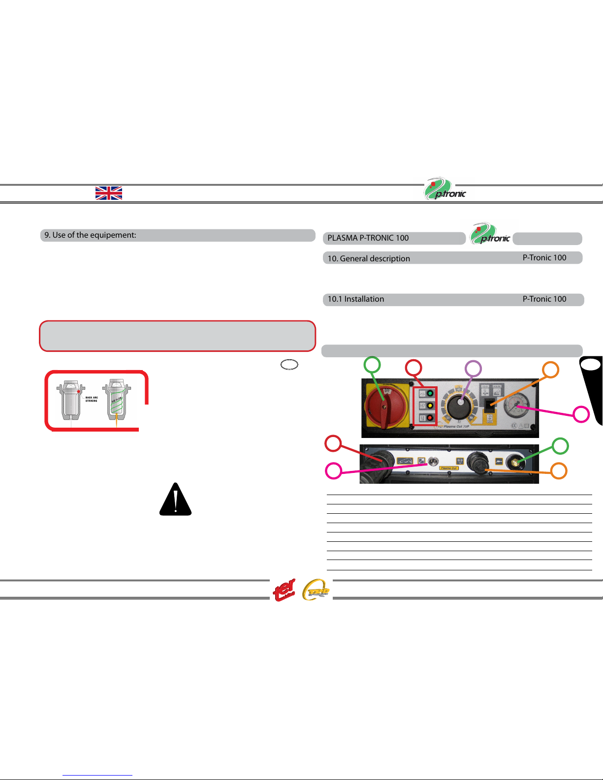
9. Use of the equipement:
A) Connect the earth clamp cable to the work piece
B) Connect the machine to the power supply net and turn ON the power
switch (8). The green led ON/OFF light on
The yellow led lights up if the torch safety circuit is open
The red led lights up in case of low pressure, wrong voltage supply, or
thermic alarm
C) With the selector (3), choose the cutting mode
D) Check the air pressure on the manometer and adjust eventually by using
the pressure reducer knob ( 5) at 5,5-6 bars. Make sure the pressure stays
at the same level during cutting
E) Set the current value with the knob ( 1 ) according to the basic material tickness
F) Press the torch trigger: the pilot arc stricks, becoming cutting arc as
soon as you will place the torch on the work
piece.
P-TRONIC 70 generator does not work with high-
frequency arc ignition: it uses the no HF technol-
ogy with BACK STRIKING system. The torch can
work only if the generator is connected to the
compressed air plant.
G) The pilot arc stops automatically after about 5 seconds if you do not place
the torch on the work piece
H) Once the cutting process is terminated release the torch trigger: the air
ow will continue to allow the cooling down of the torch
Warning: never aim the plasma jet towards people or foreign objects !
PLASMA P-TRONIC 100
10. General description
This apparatus is a constant direct current (DC) generator, designed to cut elec-
tro conductive materials (metals and alloys) by a plasma arc process. The plas-
ma gas is generated by using compressed air.
10.1 Installation
The machine needs to be supplied with clean and dry air. Set the air pressure
at 5,5-6,0 bars and make sure it does not change during the cut; a bad and/or
uncorrect air supply generates problems on the cutting quality and the torch
might be damaged too.
4
5
7
6
83
9
2
1
1 Output current knob: it sets the output cutting current
2 Manometer: it shows the air pressure (bar) during the cut
3 Cutting mode selector: grating, standard stand o, gouging
4 Earth clamp socket
5 pressure regulator knob
6 remote control socket
7 torch connector
8 ON/OFF switch
9 Monitor Leds
10.2 Front panel description P-Tronic 100 model
P-Tronic 70
P-Tronic 100
P-Tronic 100
P-Tronic 100
P-Tronic 100
P-TRONIC 100
GB
English
Instruction Manual P-Tronic 40P - 70 - 100
WARNING: the generator is equipped with a TER PT-100 plasma torch, cod
Z0042AA 6 mt long. This torch has to be considered as integral part of the
generator and its functioning and safety are guaranteed only with the origi-
nal torch. For any spare parts refer to the appendix list.
The torch is equipped with a safety circuit which prevents any accidental
contacts with conductive elements: the generator does not work if the safety
circuit is activated.
Switch always the machine OFF when working on the torch.
The generator can work in three dierent modes:
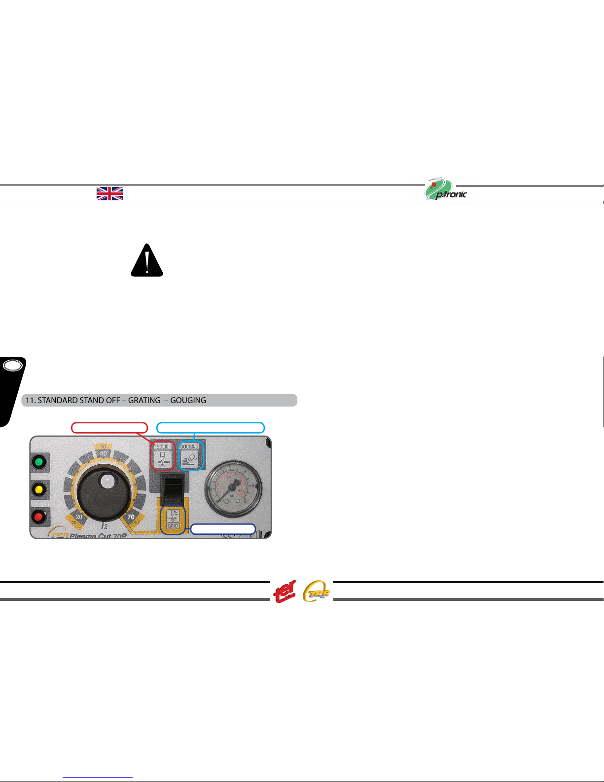
11. STANDARD STAND OFF – GRATING – GOUGING
SOLID CUT GOUGING APPLICATION
GRATING CUT
- 10 -
P-Tronic 100

GB
English
Instruction Manual P-Tronic 40P - 70 - 100
11.1 Standard Stand O in Solid Cutting
This is the typical and most commun cutting type; you can adjust the current from a minimum of 20A to a maximum of 100A. Once the cutting is terminated the arc strikes off and it can
be reactivated pressing the torch trigger once again. Use always the spacer (11) unless you have particular precision needs as described in “GRATING” paragraph.
The solid cutting can be performed in three modes:
A) Contact, precison cutting without using the spacer
B) Standard stand o for a current up to 70A
C) Standard stand o for a current higher than 70A
A) Contact precision cutting
Use Code
3 electrode Z0060AA
4 gas diuser Z0061AA
6 cutting tip 0,9 Z0063AA
9 outer nozzle Z0070AA
P-Tronic 100
B) Standard stand o for current up to 70A
Use Code
3 electrode Z0060AA
4 gas diuser Z0061AA
9 outer nozzle Z0070AA
11 double pointed spacer Z0072AA for current 40÷50 A
7 tip cutting 1,0 Z0064AA for current 40÷50A
7 tip cutting 1,1 Z0065AA for current 50÷60A
7 tip cutting 1,2 Z0066AA for current 60÷70A
C) Standard stand o for current 70A - 100A
Use Code
3 electrode Z0060AA
5 gas diuser Z0062AA
10 outer nozzle Z0071AA
11 double pointed spacer Z0072AA
8 tip cutting 1,4 Z0067AA for current 80÷90A
8 tip cutting 1,5 Z0068AA for current 100÷110A
8 tip cutting 1,6 Z0069AA for current 110÷120A
Note: the current must be set less than 40A, it is suggested the grating set.
Note: the spare parts are the same if the straight automatic
torch is used.
P-Tronic 100
P-Tronic 100
P-Tronic 100
- 11 -

GB
English
Instruction Manual P-Tronic 40P - 70 - 100
11.3 Grating
In GRATING cut position, the minimum current stays at 20A and the maximum at 40A.
When the arc moves from the solid to the grating open area, the generator returns automatically in pilot arc condition and the cutting arc starts again touching a new
solid area. We recommand the stand o spacer to improuve the spare parts life and the use of the tip (6)
11.2 Standard Solid Cutting
Contact Cutting:
in certain applications the contact cutting may be required even with current over 40A (ex.:high cutting speed on thin metal sheet or on high ticks where an high cutting precision is required).
In those application use spare parts described in the picture.
Use for current 40÷70A code
4 gas diuser Z0061AA
15 outer nozzle Z0096AA
16 shield cup Z0140AA
12 Contact tip Ø 1,0 | for current 40÷55A Z0093AA
12 Contact tip Ø 1,2 | for current 55÷70A Z0094AA
Use for current 70÷100A code
5 gas diuser Z0062AA
15 outer nozzle Z0096AA
17 shield cup Z0097AA
13 contact tip Ø 1,5 | for current 100A Z0095AA
Use code
4 gas diuser Z0061AA
6 contact tip Ø 0,9 Z0063AA
9 outer nozzle Z0070AA
11 doubler pointer spacer Z0072AA
Consider that the cutting width is about twice as much the tip diameter.
This position (grating) is suggested even for precision cuttings, on thin metal sheets
(thickness less than 6 mm): take o the spacer 11 and use contact cutting.
P-Tronic 100
P-Tronic 100
- 12 -

GB
English
Instruction Manual P-Tronic 40P - 70 - 100
12. Use of the equipement:
A) Connect the earth clamp cable to the work piece
B) Connect the machine to the power supply net and turn ON the power
switch (8). The green led ON/OFF light on
The yellow led lights up if the torch safety circuit is open
The red led lights up in case of low pressure, wrong voltage supply, or
thermic alarm
C) With the selector (3), choose the cutting mode
D) Check the air pressure on the manometer and adjust eventually by using
the pressure reducer knob ( 5) at 5,5-6 bars. Make sure the pressure stays
at the same level during cutting
E) Set the current value with the knob ( 1 ) according to the basic material tickness
F) Press the torch trigger: the pilot arc stricks, becoming cutting arc as
soon as you will place the torch on the work
piece. P-TRONIC 100 generator does not work
with high-frequency arc ignition: it uses the no
HF technology with BACK STRIKING system. The
torch can work only if the generator is connected
to the compressed air plant.
G) The pilot arc stops automatically after about 5 seconds if you do not place
the torch on the work piece
H) Once the cutting process is terminated release the torch trigger: the air
ow will continue to allow the cooling down of the torch
Warning: never aim the plasma jet towards people or foreign objects !
11.4 Gouging
In GOUGING position you can remove material with a high eciency; the
current regulation from 20A up to 100A enables the increasing of the groove’s
deep.
Use the following spares on the torch:
Use code
4 gas diuser Z0061AA
14 tip gouging Z0092AA
15 outer nozzle Z0096AA
18 gouging shield cup Z0090AA
P-Tronic 100 P-Tronic 100
- 13 -
GB
English
Instruction Manual P-Tronic 40P - 70 - 100
- 14 -
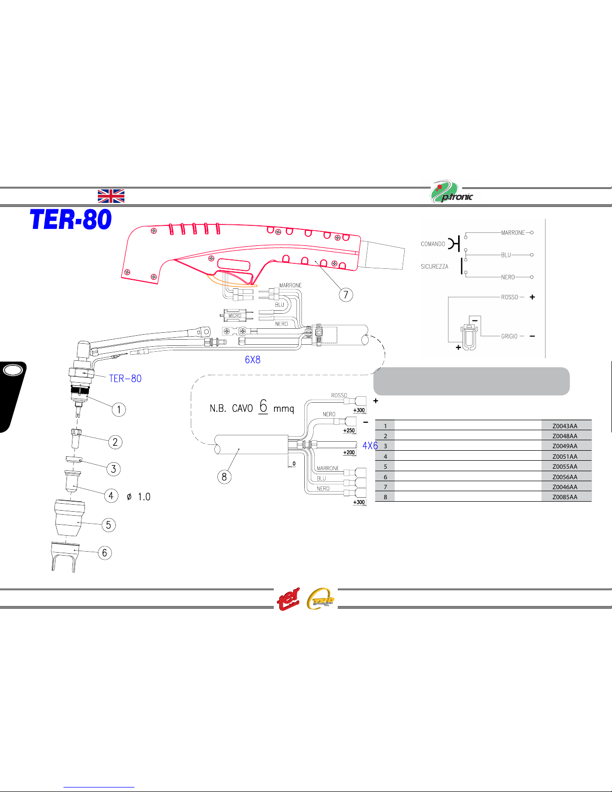
POS. DESCRIPTION CODE
1 TER - 80 torch body Z0043AA
2 TER - 80 electrode Z0048AA
3 TER - 80 diusor Z0049AA
4 TER - 80 tip cutting 1,0 Z0051AA
5 TER - 80 retaining cup Z0055AA
6 TER - 80 spacer 2 points Z0056AA
7 TER - 80 handle kit Z0046AA
8 TER - 80 direct 6 m. cable Z0085AA
13. TER - 80 direct (for p-tronic 40P)
Complete torch cod. Z0132AA

GB
English
Instruction Manual P-Tronic 40P - 70 - 100
- 15 -
14. TER - 80 (for p-tronic 70)
Complete torch cod. Z0133AA
POS. DESCRIPTION CODE
1 TER - 80 torch body Z0043AA
2 TER - 80 electrode Z0048AA
3 TER - 80 diusor Z0049AA
4 TER - 80 tip cutting 1,2 Z0053AA
5 TER - 80 retaining cup Z0055AA
6 TER - 80 spacer 2 points Z0056AA
8 TER - 80 6 m. cable Z0151AA
9 TER - 80 handle kit Z0046AA
10 TER - 80 central adaptor kit Z0152AA

GB
English
Instruction Manual P-Tronic 40P - 70 - 100
POS. DESCRIPTION CODE
1 TER - 100 torch body Z0057AA
2 TER - 100 electrode Z0060AA
3 TER - 100 diusor Z0062AA
4 TER - 100 tip cutting 1,5 Z0068AA
5 TER - 100 outer nozzle Z0071AA
6 TER - 100 double pointed spacer Z0072AA
8 TER - 100 handle kit Z0046AA
9 TER - 100 6 m. cable Z0151AA
10 TER - 100 central adaptor kit Z0152AA
15. TER - 100 (for p-tronic 100)
Complete torch cod. Z0042AA
9
- 16 -
This manual suits for next models
2
Table of contents
Popular Welding System manuals by other brands

Riland
Riland TIG 200 AC/DC operating manual

MasterCraft
MasterCraft MIG 180 instruction manual

Lincoln Electric
Lincoln Electric PANTHER K2874-2 Operator's manual

Cebora
Cebora SoundMIG 2035/M Pulse instruction manual

REHM
REHM INVERTIG.PRO digital 240 DC, 240 AC/DC operating instructions

WELDKAR
WELDKAR WK PLASMA 5035 COM PFC instruction manual


INE
INE SkyLine KME 3000 TY4 operating manual

Migatronic
Migatronic AUTOMIG2 183i instruction manual

Habasit
Habasit PQ-18 Use and maintenance manual

Lincoln Electric
Lincoln Electric SAF-FRO PRESTOTIG 200 AC/DC Operator's manual

Lincoln Electric
Lincoln Electric SYNERGIC 7 AND 7H IM557 Operator's manual

Lincoln Electric
Lincoln Electric PRO-CUT SVM146-A Service manual