PA SDI-Drives Midi User manual

PA SDI-Drives Midi™
PA SDI-Drives MaxiTM
SDI Interface Manual
Edition 07.44

PA SDI-Drives Midi™ / Maxi™ Edition 07.44 Power Automation
Type of documentation Project planning
Intention of the document This document gives information about
•Installation
•Hardware
Previously published editions: Edition Comment
07.44 First Edition
Protective note All rights reserved. No part of this work may be reproduced in any
form (by printing, photocopying, microfilm or any other method) or
stored, processed, copied or distributed by electronic means, without
the written permission of Power Automation
Remark Technical changes to improve the performance of the equipment may
be made without prior notice!
Publisher Power Automation GmbH
Gottlieb-Daimler-Strasse 17/2
D-74385 Pleidelsheim
Phone: +49 (0) 7144-899-0
Fax: +49 (0) 7144-899-299
SDI Interface Manual 2

PA SDI-Drives Midi™ / Maxi™ Edition 07.44 Power Automation
0. Contents
1. GENERAL 4
1.1 Description...................................................................................................................................... 4
1.2 Standards ........................................................................................................................................ 4
2. INSTALLATION / SETUP 5
2.2 LED Processing .............................................................................................................................. 5
2.3 Safe Restart Lock (only SDI/RL – Interface)................................................................................. 6
2.3.1 Implementation....................................................................................................................... 6
2.3.2 Principle of Operation............................................................................................................ 7
2.3.3 Additional Safety Notes ......................................................................................................... 8
2.3.4 Functional Test....................................................................................................................... 9
2.3.5 Simple Connection Example using Contact Switches...................................................... 10
2.3.6 Example using Safety PLC .................................................................................................. 11
3. HARDWARE 12
3.1 Technical Data............................................................................................................................... 12
3.2 Pinning........................................................................................................................................... 13
3.3 Address switch ............................................................................................................................. 14
3.4 Analog inputs................................................................................................................................14
3.4.1 Four independent inputs...................................................................................................... 14
3.4.2 Two differential inputs ......................................................................................................... 15
SDI Interface Manual 3

PA SDI-Drives Midi™ / Maxi™ Edition 07.44 Power Automation
1. GENERAL
1.1 Description
The SDI – Interface is mounted in the PA SDI-Drives Midi™ / Maxi™.
It enables the full functionality of the drive.
It is connected to a controller via a special synchronous serial high speed connection
•Full setup of the parameters, actual values, commands and scope function
•Real time communication every 1ms to 8ms
•Firmware download
Lock” – function (SDI/RL –
Inte ce
•ENABLE input, LOCK input, EN-BRAKE input and safe
tion relay output “SAFE LOCK” (only for SDI/RL – Interface)
1.2
Safe sta
•EN ISO 13849 Safety of machinery – Safety-related parts of control systems
•EN 954-1 Safety of machinery – Safety-related parts of
Back to Content
Two hardware versions are available. One with “Safe Restart
rfa and one without the safety function SDI – Interface
•4 digital inputs with capture functionality (position latch)
•4 x +/- 10V analog inputs (resolution 12Bit), either 4 channel single ended or 2
channel differential)
“Safe restart lock” with
condi
Standards
ty ndards
•EN 60204 Safety of machinery – Electrical equipment of machines
control systems
s
SDI Interface Manual 4

PA SDI-Drives Midi™ / Maxi™ Edition 07.44 Power Automation
2. INSTALLATION / SETUP
2.2 LED Processing
The SDI – Interface and the SDI/RL – Interface have two LEDs, a red and a green, that
display the actual communication state.
Green LED State
Off No bus communication at all
On Bus communication available
Red LED State
Off No drive related bus communication
On Drive related bus communication available
Back to Contents
SDI Interface Manual 5

PA SDI-Drives Midi™ / Maxi™ Edition 07.44 Power Automation
2.3 Safe Restart Lock (only SDI/RL – Interface)
PA SDI-Drives Midi™ / Maxi™ in combination with the SDI/RL – Interface, supports the
safety function “safe restart lock” according to the requirements of the control category of
EN 954 Part 1 and Part 2 category 3 and ISO 13849 performance level “d”.
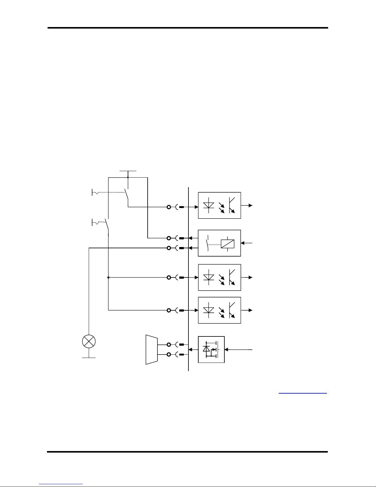
For this purpose, the drive has two independent safety paths in parallel connection.
The safety category is reached, when the signal ”SAFE LOCK” is additionally verified.
In addition to that, also the holding brake is part of the circuitry. The control category of
EN 954 Part 1 and Part 2 category 1 and ISO 13849 performance level “c” is reached for
the electrical circuitry of the holding brake processing. If the holding brake supply input
+24V-BR has an additional circuitry; the safety category can be increased.
2.3.1 Implementation
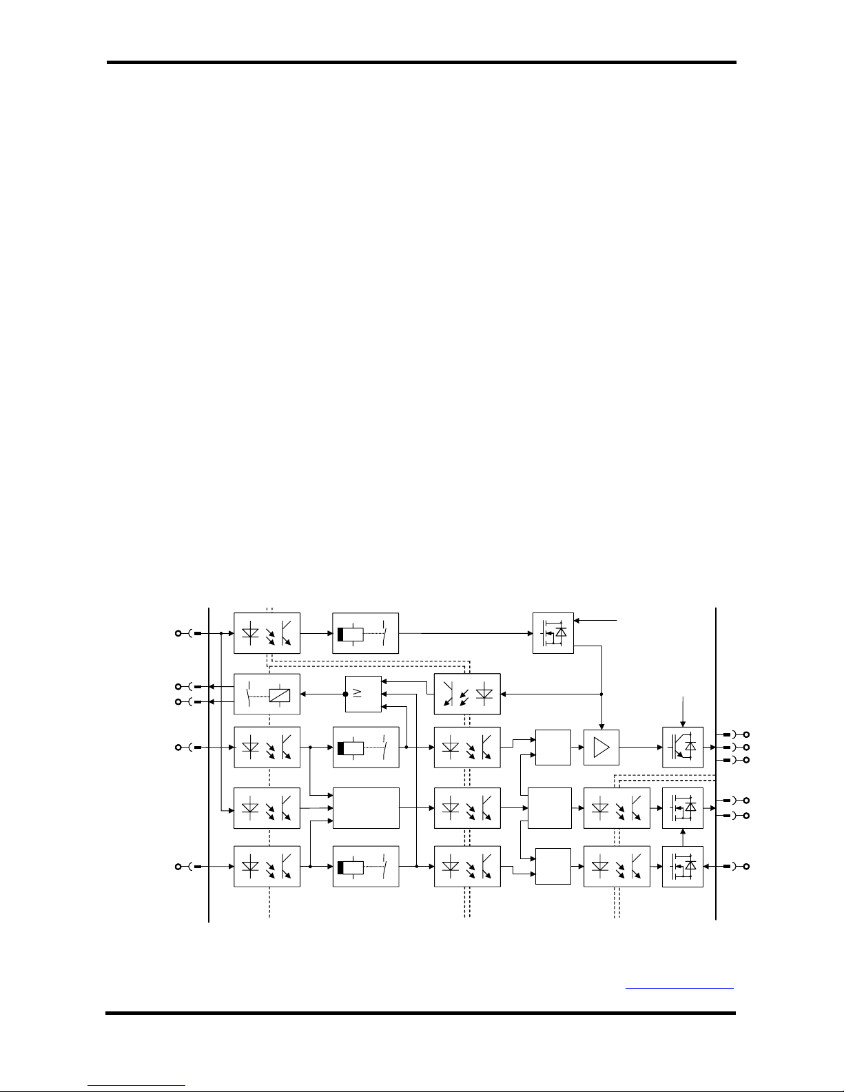
The following block diagram gives an overview over the internal circuitry.
The signals LOCK and ENABLE are directly connected to the microcontroller and also to
two independent switch-off delayed circuitries, which delay the signals in hardware for
about 0.5sec.
The delayed LOCK – signal switches off the power supply of the driver for the IGBT-power-
stage. The delayed ENABLE – signal switches off the control signals to the power stage, so
two independent signals switch off the power stage in different ways.
The signal EN-BRAKE is also galvanic isolated from the internal electronic potential by opto
coupler and is connected to a switch-off delayed circuitry, which delays the signal in
hardware for about 0.5sec. The undelayed signal is connected to the microcontroller and
the delayed signal switches off the 24V power supply of the holding brakes.
The effect of the three signals is supervised and only if all signals are in the safe state, the
relay “SAFE LOCK” closes the contact between S1 and S2.
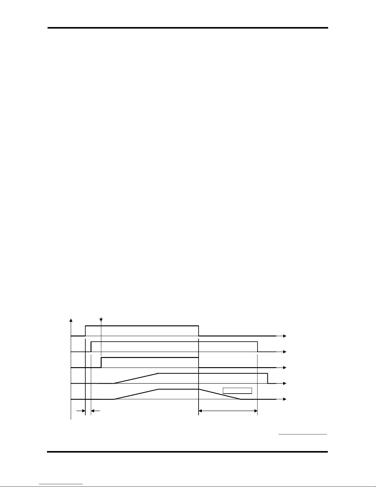
If one or all of the signals ENABLE, LOCK or EN-BRAKE are switched off in emergency
stop condition, the drive decelerates the motors (stop category 1 according to EN 60204-1).
If all three signals are switched off, the drive is brought into the safe restart lock condition
after the delay time of 0.5sec.
Motor
Low power
supply for power
stage driver
Mains power
supply
0.5s
0.5s
µP
1
X10
S1
S2
LOCK
ENABLE
X3, X4, X5
Power stage potentialElectronic potential
Digital I/O
potential
UU
VV
WW
11
22
55
66 &
µP
B+B+
B-B-
&
24V Aux. potential
0.5s
EN-BRAKE
77 11
X1A
SAFE
Block diagram of the safe restart lock circuitry
Back to Contents
SDI Interface Manual 6

PA SDI-Drives Midi™ / Maxi™ Edition 07.44 Power Automation
2.3.2 Principle of Operation
The function “safe restart lock“ uses three digital inputs, to bring the drive in this state.
•ENABLE – input
•LOCK – input
•EN-BRAKE – input
ed
ardware for about 0.5sec. After this time, the inputs force the drive in the safe state.
The ENABLE – input inhibits the control signals of the power stage.
-
stage. This is the second path to switch off the control signals of the power stage.
-
the axes, the enable input has to be set to “high” to be able to enable the drives.
combined in or – logic
utput
1/S2 is closed and symbolises the state “safe restart lock” after about 0.6 sec.
N= 1 or the corresponding bit in
the control word) has to be set to enable the power stage.
All three signals have to be open or low, to enable the “safe restart lock” function. To
simplify the external emergency stop circuitry in the cabinet, the three inputs disable the
drive directly via microcontroller. The microcontroller decelerates the motor to zero spe
and disables the power stage. In parallel, the three inputs are switched-off delayed by
h
-
The LOCK – input switches off the supply voltage of the drivers of the IGBT power
The EN-BRAKE – input switches the 24V supply of the holding brake off. This
input can be set to high to release the holding brake for manual move of the
mechanics (in combination with K-BRAKE = 1) without loosing the safe restart
lock of the power stage. Even if no holding brake is connected to one or more of
The state of the supply voltage (on/off) of the drivers is fed back and
with the internal ENABLE signal and the internal EN-BRAKE signal.
Only if the three signals are in the safe state, the “SAFE LOCK” relay contact of o
S
When the inputs LOCK, ENABLE and EN-BRAKE are switched to high, the drive is not
enabled directly. In addition to that, a software enable (K-E
LOCK or ENABLE
or EN-BRAKE
„SAFE“ Relay Output
(High = Contact Closed
Internal Enable
Software Enable
Speed Set Point
from Controller
Actual Speed
0.6 sec0.1 sec
G-EMRAMP
Back to Contents
SDI Interface Manual 7

PA SDI-Drives Midi™ / Maxi™ Edition 07.44 Power Automation
2.3.3 Additional Safety Notes
•Only qualified personnel are permitted to install and set up the “safe restart lock”
function
•All control components (switches, relays, PLC, etc.) and the control cabinet mus
comply wit
in
– Door – switches, etc. with protection class IP54 as minim
–
t
h the requirements of the EN 954-1, EN 954-2 and ISO 13849. This
cludes:
um
Control cabinet with protection class IP54 as minimum
•dback contact)
outside the control cabinet.
•art lock” (e.g. force to
the load by hanging load) additional measures have to be provided (e.g. double-disc
ailure to observe this precaution can result in severe injury and equipment damage.
e m hed off by e.g. a mains contactor in
cleaning, maintenance and repair operations
w any one of these instructions will result in death, ser
quipment damage.
Back to Content
•Use insulated wire end sleeves
•Control cable length of the inputs ENABLE, LOCK, EN-BRAKE and output
“SAFE LOCK” is limited to 25 m max.
All safety-relevant cables (e. g. control cable for the safety relay, fee
has to be installed e. g. in a cable duct, if pass
Make sure, that short circuits between single cables are excluded!
For further measures see EN 954-2, table D4
When an external force is likely to act with the function ”safe rest
spring set brake, instead of permanent magnetic-excited brake)
F
Th ains power supply of the drive has to be switc
case of:
•
•long down time periods
Failure to follo ious injury or
e
s
SDI Interface Manual 8

PA SDI-Drives Midi™ / Maxi™ Edition 07.44 Power Automation
2.3.4 Functional Test
The functional test of the safe restart lock is necessary, to check the correct mode of
operation. This procedure has to be done:
•after installation
•on a regular basis, after one year at the latest
When the function check leads to impermissible states, check for errors and then restart the
commissioning of the machine. If the function test has been unsuccessful, don’t start the
achine.
est specification
m
ailure to oberserve this precautions can result in severe injury.F
T
•ck” circuitry directly at the terminals
of the S1300 using the state table below.
t I
•Check the complete safety relevant circuitry for operational reliability
Check the function of the “Safe Restart Lo
S ate of the nputs
LOCK ENABLE EN-BRAKE all Inputs
Description
Nor-
signal of State of Output
“SAFE LOCK”
Low Low Low High C r
rake
ontact closed
after 0.6 sec
Safe state for moto
and holding b
High Low Low Low Contact open Unsafe state
Low High Low Low Contact open Unsafe state
High High Low Low Contact open Unsafe state
Low Low High Low Contact open
ble
= 1
Safe state for motor,
manually operation of
possi
holding brake
with K-BRAKE
High Low High Low Contact open Unsafe state
Low High High Low Contact open Unsafe state
High High High Low
transition of
NOR-signal
Normal operation
Contact opens
after 0.1 sec of
High/Low
the
Back to Contents
SDI Interface Manual 9

PA SDI-Drives Midi™ / Maxi™ Edition 07.44 Power Automation
2.3.5 Simple Connection Example using Contact Switches
In order to reach the control category of EN 954 Part 1, Part 2 category 3 and ISO 13849
performance level “d”, the signal ”SAFE LOCK” (S1 and S2) must be additionally verified.
This requires external wiring. The external wiring must be adapted to the existing safety
concepts and checked for a reliable operation.
The holding brake circuitry reaches EN 954 Part 1, Part 2 category 1 and for the electrical
circuitry ISO 13849 performance level “c”.
This circuit shows the minimum external wiring of the axis module, with switching contact
for a motor with brake.
The ENABLE and EN-BRAKE signals are switched by the same switch. In this case, the
axis cannot be moved manually. If this function is needed, an additional switch for
EN-BRAKE is needed.
The function of this circuit is: The safe restart lock is activated, when the lamp is on. In this
case, only the visual feedback is used.
X10
S1
S2
LOCK
ENABLE
11
22
55
66
B+B+
B-B-
X3, X4, X5
Y1
H1
24V-GND
24V
EN-BRAKE
77
SAFE
Back to Contents
SDI Interface Manual 10

PA SDI-Drives Midi™ / Maxi™ Edition 07.44 Power Automation
2.3.6 Example using Safety PLC
In order to reach the control category of EN 954 Part 1, Part 2 category 3 and ISO 13849
performance level “d”, the signal ”SAFE LOCK” must be additionally verified. This requires
external wiring. The external wiring must be adapted to the existing safety concepts and
checked for the correct operation.
The holding brake circuitry reaches EN 954 Part 1, Part 2 category 1 and ISO 13849
performance level “c” for the electrical circuitry.
The Safety-PLC must have two (or three) safe outputs and one safe input to bring the
S1300 into the safe state. One side of the “SAFE LOCK” relay contact (S1/S2) is connected
to 24V and the other to the PLC Input 1.
I/O at interface board Separate manual holding
brake operation Holding brake controlled
only in operation mode
LOCK PLC Output 1 PLC Output 1
ENABLE PLC Output 2 PLC Output 2
EN-BRAKE PLC Output 3 PLC Output 2
“SAFE LOCK” PLC Input 1 PLC Input1
The PLC must be programmed to meet the following requirements:
•The output and the input states are checked for plausibility according to the
following table
•If an impermissible state is detected, the entire system is put into a safe s
If the state of the inputs has changed from high to low, the contact of the
“SAFE LOCK” relay closes by about 0.6 sec delayed. If the state of the inputs
has changed from low to
tate
•
high, the contact of the “SAFE LOCK” relay opens by
about 0.1 sec delayed.
t IS ate of the nputs
LOCK ENABLE EN-BRAKE all Inputs “SAFE LOCK” Description
Nor-
signal of State of Output
Low Low Low High C r
rake
ontact closed
after 0.6 sec
Safe state for moto
and holding b
High Low Low Low Contact open Unsafe state
Low High Low Low Contact open Unsafe state
High High Low Low Contact open Unsafe state
Low Low High Low Contact open
le
= 1
Safe state for motor,
manually operation of
holding brake possib
with K-BRAKE
High Low High Low Contact open Unsafe state
Low High High Low Contact open Unsafe state
High High High Low
after 0.1 sec of
tr
NOR-signal
Normal operation
Contact opens
Low/High
ansition of the
Back to Contents
SDI Interface Manual 11

PA SDI-Drives Midi™ / Maxi™ Edition 07.44 Power Automation
3. HARDWARE
3.1 Technical Data
DIM
SDI – Interface / SDI/RL – Interface
Outputs
V DC max. 30, AC max 42
Relay “SAFE LOCK”, free Contact (NO), only
for SDI/RL – Interface A Min. 10µ, Max. 0.5
Digital Inputs
Vdc Low 0 … 7 / high 12 … 30
Digital Inputs (LOCK, ENABLE, EN-BRAKE)
only for SDI/RL – Interface mA 10 at 24V input voltage
Vdc Low 0 … 7 / high 12 … 30
Digital Inputs (IN1 to IN4) mA 10 at 24V input voltage
Start delay (IN1 to IN4) µs Ca. 1
Switch off delay (IN1 to IN4) µs Ca. 2
Jitter (IN1 to IN4) µs ± 0,5
Analog Inputs
Vdc +/- 10V
Analog Inputs AIN1 to AIN4,
resolution 12Bit (about 5mV per LSB) Input
resistance 42 kOhm
Connections
Digital / Analog In-/Outputs (X10) ─Mini-Combicon FMC 1,5 / 8 – ST – 3,5
(Spring-Cage Type)
J1 SDI input from last participant ─RJ45
J2 SDI output to next participant ─RJ45
Back to Contents
SDI Interface Manual 12

PA SDI-Drives Midi™ / Maxi™ Edition 07.44 Power Automation
3.2 Pinning
Connector J1 is the SDI input connector from the controller / last drive and J2 the SDI
output connector to the next drive.
J1 J2X10
1
9
8
16
Host Com
LED1 (green)
Slave Com
LED2 (red)
11
SW1
The pinning of the connectors is:
Connector X10 Pin Function: digital In/Output
S1 1 Safety function relay “SAFE LOCK”, free contact (NO)
S2 2 Safety function relay “SAFE LOCK”, free contact (NO)
IN1 3 Digital Input 1
IN2 4 Digital Input 2
LOCK 5 Switch on of the driver supply of the power stage
ENABLE 6 Enables the power stage
EN-BRAKE 7 Enables the the holding brake supply
24V-GND 8 Ground for the digital inputs
IN3 9 Digital Input 3
IN4 10 Digital Input 4
AGND 11 Analog ground
AIN1 12 Analog input 1
AIN2 13 Analog input 2
AIN3 14 Analog input 3
AIN4 15 Analog input 4
AGND 16 Analog ground
SW1 is the address switch for the bus address of the drive.
SDI Interface Manual 13

PA SDI-Drives Midi™ / Maxi™ Edition 07.44 Power Automation
3.3 Address switch
The SDI bus system needs the setting of the slave address at the drives. Therefore the
drive has a address switch SW1 (see page 13). Set the address by using a small screw
driver at SW1.
Back to Contents
3.4 Analog inputs
The SDI – interface has four analog inputs. They can be used in two different modes, single
ended or differential.
The selection of the two modes is done in the controller software.
3.4.1 Four independent inputs
In this mode, four independent analog inputs are available.
Connect the analog signal to the input and the return (ground) to AGND (pin 11 or pin 16 of
X10).
-
+
-
+
Interface
X10
2V
20k 22k
2V
AIN1 (12)
AIN2 (13)
20k 22k
AGND (11, 16)
-
+
-
+
2V
20k 22k
2V
AIN3 (14)
AIN4 (15)
20k 22k
Back to Contents
SDI Interface Manual 14

PA SDI-Drives Midi™ / Maxi™ Edition 07.44 Power Automation
3.4.2 Two differential inputs
The inputs AIN1 and AIN2 are used for one pair of inputs and AIN3 and AIN4 as the
second pair. AIN1 and AIN3 are the inverted inputs and AIN2 and AIN4 are the non
inverted inputs
-
+
-
+
Interface
X10
2V
20k 22k
2V
AIN1 (12)
AIN2 (13)
20k 22k
(inverted Input (-)
(non inverted Input (+)
AGND (11, 16)
-
+
-
+
2V
20k 22k
2V
AIN3 (14)
AIN4 (15)
20k 22k
(inverted Input (-)
(non inverted Input (+)
Back to Contents
SDI Interface Manual 15
This manual suits for next models
1
Table of contents