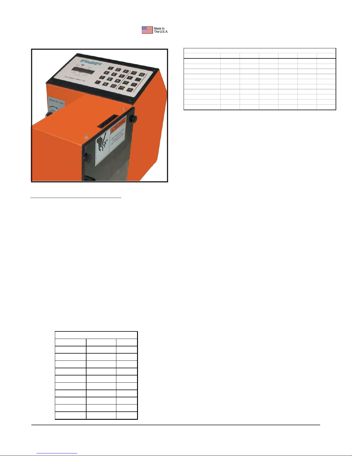
Model MMC200 Multi-Material Cutter
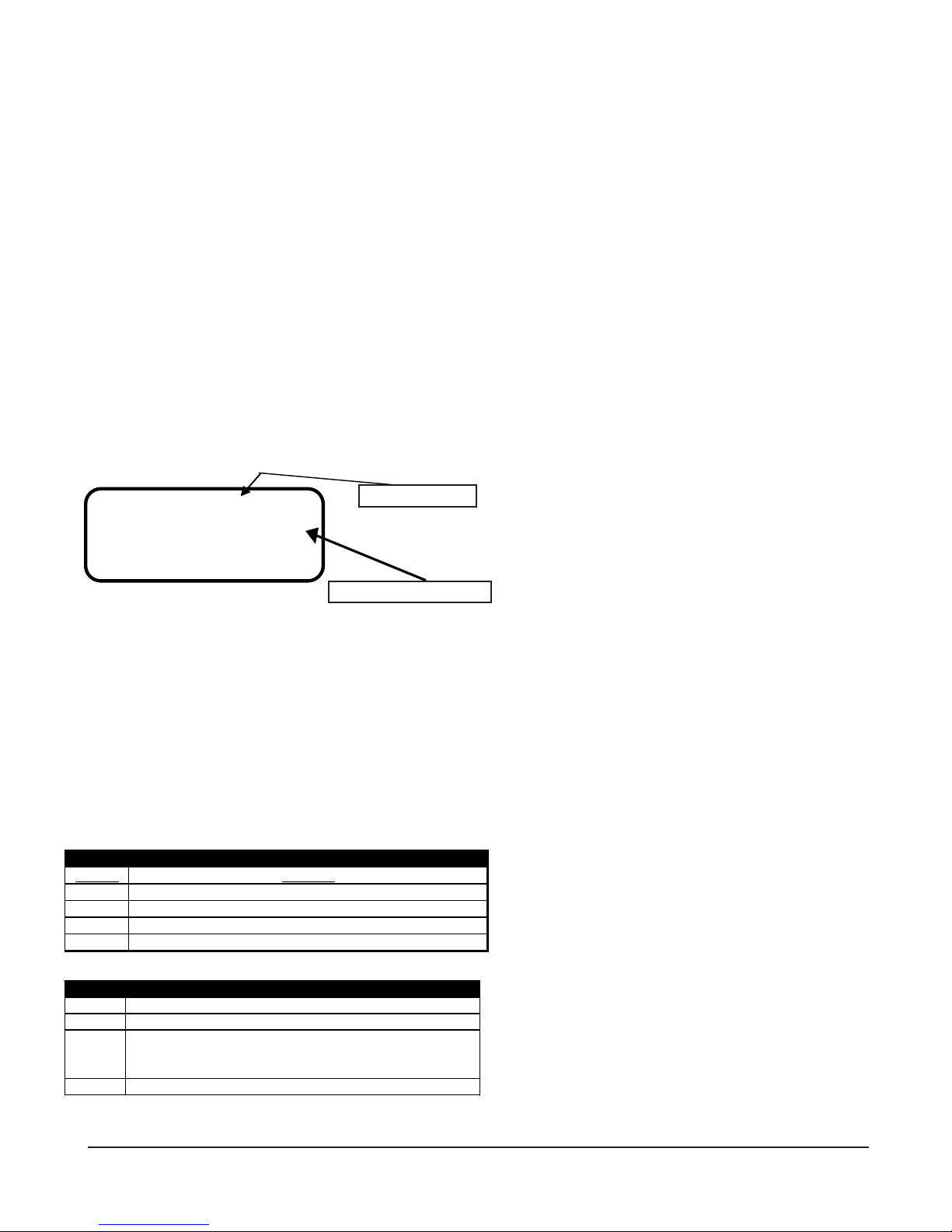
The current batch number is shown beside the #
at the top right. The cursor will be flashing just be-
fore the in (inch), indicating that the field is cur-
rently editable. In general, the line being edited will
display a blinking cursor. Press the <ENTER> key
to accept the default of inches, or press the <+>
or <-> key to toggle to cm, for centimeters, then
press the <ENTER> key to store cm. Each time
the <ENTER> key is pressed, the cursor advances
to the next parameter.
Enter a value for the length parameter. If the
<ENTER> key is pressed accidentally before a
value is entered, press the <ESC> key to go back
to the main batch select menu. If a mistake is made
during data entry, press the <BACKSPACE> key
to back space over the entry. If the <ENTER> key
has been pressed, press the <ESC> key and start
over. All values entered so far will have been stored,
so you would only have to press the <ENTER>
key until you returned to the parameter where that
is incorrect-the values would not have to be en-
tered again. The cut length parameter requires a
value between .01 and 99,999 to be entered. The
limitation here is that the value can be a maximum
of 6 characters, including the decimal place. For
example, 123456, 123.45 and 1234.5 are permis-
sible but the value 1234.56 isn’t allowed. The
MMC200 is capable of 1% cut length accuracy only,
so, it doesn’t make sense to enter a decimal place
value in lengths over 100 (inches or centimeters).
Due to variations in materials, pre-feed systems
and feed wheel pressure, actual cut length may
vary from the inputted length by a proportional
amount. If the cut lengths are consistent with each
other, the machine requires no further adjustment
to pre-feed system or feed wheel pressure. The
MMC200 incorporates a length compensation fea-
ture to provide an easy adjustment in these cases.
The length can be compensated +/-1% to +/- 10%
of the inputted length. The length compensation
display will show (-) for a negative value. Example:
If 10" (25.4cm) is entered as the desired length,
but the actual average cut piece measures 9.8"
(24.9cm), a length compensation of +2% will
increase the cut length by .200 (0.5 cm) to the
desired 10" (25.4 cm). The <+> or <-> keys may
be used to add or decrease length compensation
value. NOTE: Often it will not be known if length
compensation is needed until after a trial run is
completed. When programming a batch, leave the
field at 0 and edit the batch later if necessary to
add length compensation. Once a value has been
entered, or if the default of 0 is to be used, press
the ENTER key. The length compensation will re-
main with the batch program. An alternate, more
accurate, method would be simply to enter the
desired cut length, run several pieces, measure/
calculate the average error and add/subtract the
error to/from the targeted length as necessary (e.g.
a desired 10.00" is entered into the length param-
eter; a measured 9.82" is cut. The operator com-
pensates for this by adding 0.18" to the targeted
cut length value. The new cut length value be-
comes 10.18").
After the quantity is entered, cut rate edit screen
appears:
FEED RATE 3 #1
-MAX SPEED 8.0
-MAX ACCEL 20.0
-MAX DECEL 40.0
The default feed rate is feed rate #3, as depicted
above. The feed rate can be changed at this point
by entering a number (0 through 9) or by pressing
the <+> or <-> keys. Feed rate #3 is a good start-
ing point. Adjust this value upward if the produc-
tion rate isn’t high enough and adjust this value
down if there is a lot of slippage at the feed belts.
The units for acceleration are in revolutions per
second2 and the units displayed for speed is revo-
lution per second. Press <+> or <-> to increment
or decrement the feed rate value. As the value is
changed, the rate values are updated to show what
values are active for that feed rate. The following
table represents the maximum speed at any feed
rate of the feed belts:
NOTE: The slower the feed rate, the more accu-
rate in length the cut pieces will be. It is advised to
start with the lowest feed rate and check results,
then adjust the feed rate if desired.
If an incorrect key is pressed for a given param-
eter input (e.g. a number key is pressed at the
Production Automation • Eden Prairie, MN USA• Ph: 888-903-0333 • info@gotopac.com • www.gotopac.com • Fax 952-903-0315