3
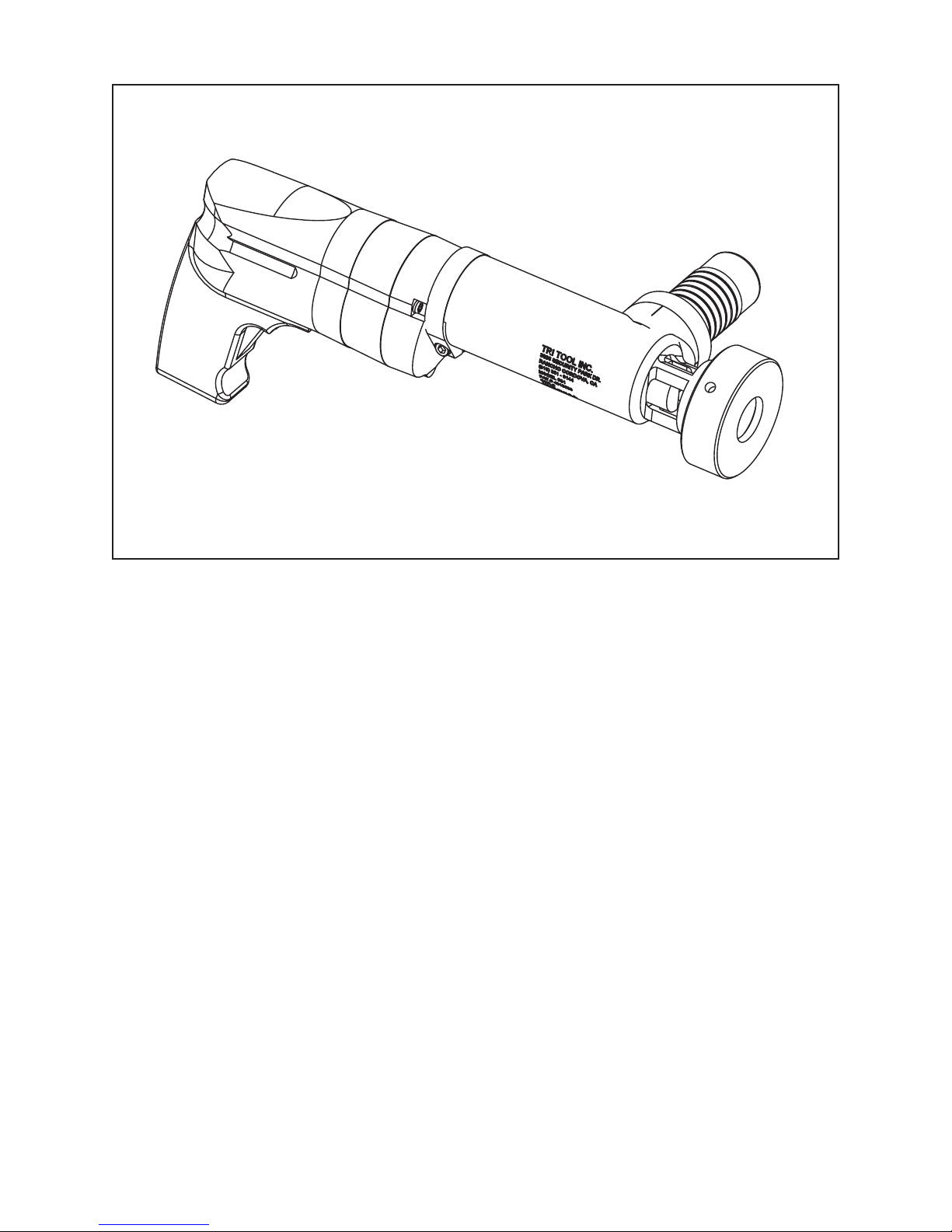
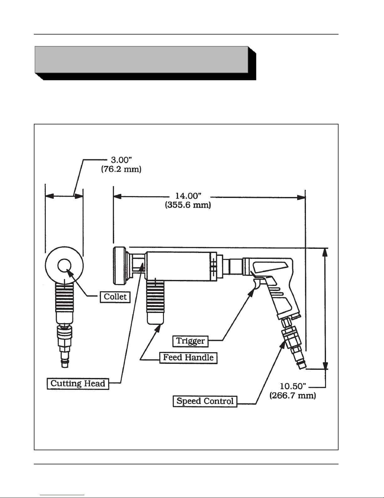
Model 301 Tube Squaring Machine
92-0630 : Rev. 060811
SAFETY PRECAUTIONS
WARNING:
IN GENERAL
When using rotating head cutting equipment, basic safety precautions should always
be followed to reduce the risk of personal injury.
Operate this tool only in accordance with specific operating instructions.
Do not override the deadman switch on the power unit. Locking down, ob-
structing, or in any way defeating the deadman switch on the power drive unit
may result in serious injury.
DRESS CONSIDERATIONS
Use standard safety equipment. Hard hats, safety shoes, safety harnesses, protec-
tive clothes, and other safety devices should always be used when appropriate.
Use safety glasses. Do not operate cutting tools without eye protection.
Dress properly. Do not wear loose clothing or jewelry. They can be caught in rotat-
ing and moving parts. Avoid slippery floors or wear nonskid footwear. If you have
long hair, wear protective hair covering to contain it.
WORK AREA
Keep the work area clean. Cluttered work areas and benches invite injuries.
Consider the work area environment. Keep the area well lit. Keep electrical cords,
cables, rags, rigging straps, and etc. clear of rotating equipment. Do not use power-
cutting tools in the presence of flammable liquids and gasses.
Keep visitors away. Do not let visitors or untrained personnel at or near operating
tools. Enforce eye protection requirements for all observers.
Do not over reach. Keep proper footing at all times.
Stay alert. Watch what you are doing. Use common sense. Do not operate tools
when you are tired.