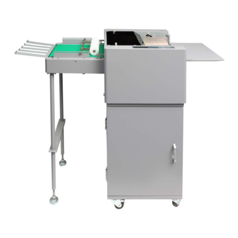
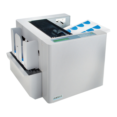
Formax FD 574 User manual

FD 574
Tabletop Cut-Sheet Cutter
OPERATOR MANUAL
5/2018


i
(→P.00 “xxxx”)
Introduction
: Introduces instructions for correct operation and maintenance of the
machine. If these instructions are ignored, the machine may not be able to
operate at optimum performance or may break down.
: Introduces restrictions for correct operation of the machine.
: Introduces information that is useful for operation and maintenance of the
machine, or information about the machine’s performance, etc.
: Indicates the page number and item containing related information.
Symbols in this manual
Thank you for purchasing the Cut Sheet Cutter FD 574.
To ensure safe and efficient prolonged use of this machine, read and thoroughly understand
this manual before using the machine.
After using this manual, be sure to keep it in a handy place to reference.
PLEASE NOTE
In the interests of upgrading our product, specifications and other data given in this manual
are subject to change without notice. If the manual contains anything that you do not
understand, contact the distributor or dealer for clarification.

ii
Various symbols and pictures are used in this manual and on the labels affixed to the machine.
These symbols and pictures provide warnings and instructions to prevent danger to you or
other personnel, and to prevent damage to office property.
The meanings of these symbols and pictures are explained below.
Indicates a high degree of potential danger. If the warning is ignored, death or serious injury
may result.
Indicates a medium degree of potential danger. If the caution is ignored, medium injury or
damage to property may result.
<Examples of Pictorial Symbols>
A circle with a line through it indicates a prohibited action.
The particular act prohibited is indicated by a picture inside the circle.
(In the example shown here, the prohibited act is disassembly.)
A black disc indicates an instruction, or sometimes a prohibited action.
The instruction itself is indicated by pictorial symbols drawn in white on the disc.
(In the example shown here, the instruction is 'Remove the plug from the outlet'.)
●Precautions for Use
WARNING
●If the machine is used after foreign matter (metal fragments, water, or liquid) has
entered the machine, this may result in fire or electric shock.
→Turn the power switch OFF, and then remove the power plug from the outlet.
Contact the sales distributor.
●If the machine is used after heat, smoke, strange smell, or other abnormality is
detected, this may result in fire or electric shock.
→Turn the power switch OFF, and then remove the power plug from the outlet.
Contact the sales distributor.
●Do not insert or drop metal, flammable material, or other matter through the
ventilation holes into the machine interior.
→Doing so may result in fire or electric shock.
●Do not place flower vases, flowerpots, cups, or water containers (including metal
containers) on top of the machine.
→Fire or electric shock may result if liquid spills inside the machine.
Notes on Safety (Please Read and Observe)
WARNING
CAUTION
Safety Precautions

iii
●Caution for Grounding
WARNING
●Use only the power cord that is provided among the accessories.
Insert the power cord plug firmly into the socket, so that proper electrical contact is
effected.
Use of any other power cord could result in imperfect grounding.
If grounding is imperfect and electrical leakage occurs, fire or electric shock could
result.
●Caution for Power Supply and Power Cord
WARNING
●Do not use a source voltage other than that specified.
Do not connect two or more loads to a single outlet.
→Doing so may result in fire or electric shock.
●Be sure to remove dust on the power plug and/or the outlet.
Using these without removing dust may have minute electric current flow to the
surface due to the humidity and cause a fire due to the heat.
→It may cause a fire or electric shock.
●Do not insert or remove the power plug with wet hands.
→Doing so may result in fire or electric shock.
●Do not damage, break, or modify the power cord.
Do not place heavy objects on, tug, or unnecessarily bend the power cord.
→Doing so may result in fire or electric shock.
CAUTION
●Remove the power plug itself, not the cord.
→Tugging the cord may damage it (expose conductors, or cause disconnections,
etc.), resulting in fire or electric shock.

iv
●Prohibition of Disassembly or Modification
WARNING
●Do not modify the machine.
→Doing so may result in fire or electric shock.
●Do not remove the rear lid, cabinet, or covers from the machine.
→The inside of the machine contains high-voltage parts, which may cause electric
shock.
●Caution for Location
WARNING
●Do not place the machine in a humid or dusty area.
→Doing so may result in fire or electric shock.
CAUTION
●Before moving the machine, remove the power plug from the outlet.
→If the cord is damaged, this may result in fire or electric shock.
●Do not place the machine in an unstable position such as on an unsteady table or
sloping area.
→If the machine drops or falls over, it may result in injury.
●Do not place the machine in a place subject to direct sunlight or heating equipment
such as a stove.
●Avoid placing the machine in a place subject to high or low temperature or high
humidity.
→The paper absorbs moisture and it may cause paper jam or creasing.
●Leave the power cord unplugged when the machine is not used for a long period.
→Insulation may deteriorate and cause an electrical fire.

v
●Caution for Cleaning
CAUTION
●Before cleaning the machine, turn off the power switch and unplug the power cord.
→If the machine is activated accidentally, injury may result.
●Do not use flammable sprays or solvents inside or near the machine.
→Gas may accumulate inside the machine causing a fire or explosion.
●Preventing Injury to Hands or Fingers
WARNING
●The center slitter contains uncovered blades. Keep your hands or fingers off inside
those.
●Use tweezers or a similar tool to remove jammed paper.
Before removing jammed paper, be sure to unplug the power cord in order to
prevent an electric shock.

vi
Keep the WARNING and CAUTION labels clean at all times.
If labels become damaged or come off, contact our service personnel.
U80001
U80002A
1.
2.
3.
<Paper infeed side>
Locations of Warning Labels

vii
U80003
U80004
1.
4.
<Paper ejection side>
<Paper ejection side
(without rear cover)>
No. Part No. Name Q'ty
1. J4-Y4040 CAUTION LABEL 2
2. M7-T3030 WARNING LABEL 1
3. K9-T1390 WARNING LABEL 2
4. L8-T1070 WARNING LABEL 1

viii
No. Part No. Name Q'ty
1. J4-Y4050 WARNING LABEL 1
2. L8-T1070 WARNING LABEL 1
<Options>
Perforator (standard/micro) unit Center slitter unit
1.
1.
U82313
2.
Paper infeed side
Open the top cover.
Upper plate (front)

ix
Chapter 2
Chapter 3
Chapter 1
Contents
Introduction............................................................................. i
Notes on Safety (Please Read and Observe)....................................ii
Safety Precautions ..............................................................ii
Locations of Warning Labels..................................................vi
Before Using This Machine
Part Names and Their Functions ................................................. 2
Appearance (Paper Infeed Side)............................................. 2
Appearance (Paper Ejection Side) .......................................... 3
Control Panel .................................................................... 4
LCD Panel ....................................................................... 5
Turning Power ON/OFF............................................................. 6
Turing Power ON ............................................................... 6
Turning Power OFF ............................................................ 7
Acceptable Paper .................................................................... 8
Basic Operation
Procedure for Using the Machine ................................................10
About Display Screens .............................................................11
Standby Screen ................................................................11
Menu Selection Screen .......................................................11
Function Setting Screen ......................................................12
Preparation Before Use ............................................................13
Setting the Support Tray......................................................13
Loading the Paper .............................................................13
Adjusting Feed Pressure according to Paper Thickness ...............15
Aligning the Paper Retaining Plates........................................16
Basic Operation .....................................................................18
Menu Selection.................................................................18
Direct Processing ..............................................................18
Standard JOB ..................................................................19
Taking Out the Cut Paper ....................................................22
Menu Selection
Custom JOB .........................................................................24
Memory No. and JOB Details................................................30
Auto Cut ..............................................................................31

x
Chapter 4
Chapter 5
Chapter 6
Chapter 7
Chapter 8
Contents
Using Useful Functions
Function Settings....................................................................36
1. Double Feed Detection ....................................................37
2. Slitter/Perforation ...........................................................38
3. Preset Counter .............................................................39
4. Speed ........................................................................40
5. Downstream Unit ...........................................................41
6. Cut Position Adjustment ...................................................42
7. JOB Display .................................................................43
8. Auto Power Off .............................................................45
9. Exit ............................................................................46
Optional Equipment
How to Use Center Slitter Unit....................................................48
Using as a Slitter...............................................................48
Using as a Gutter Deflector ..................................................49
How to Use Perforator (Standard/Micro) Unit ..................................51
Troubleshooting
If Trouble Occurs ....................................................................54
When Messages Appear...........................................................55
Corrective Action for Paper Jams ...............................................57
How to Remove Jammed Paper from Infeed Area ......................57
How to Remove Jammed Paper from Center Area or Cutter Unit ....58
Daily Maintenance
Daily Maintenance ..................................................................62
Specifications
Specifications ........................................................................64

Chapter 1
1
Before Using This Machine
This chapter contains essential information such as the names of the machine
parts, the names and functions of keys on the control panel, and the acceptable
paper etc. Please be sure to read this chapter carefully before using the
machine.
Part Names and Their Functions ..........................................................2
Appearance (Paper Infeed Side)...................................................... 2
Appearance (Paper Ejection Side) ................................................... 3
Control Panel .............................................................................4
LCD Panel ................................................................................ 5
Turning Power ON/OFF...................................................................... 6
Turing Power ON ........................................................................6
Turning Power OFF ..................................................................... 7
Acceptable Paper .............................................................................8

2
U80002
Part Names and Their Functions
Appearance (Paper Infeed Side)
1
2
3456
7
8910
No. Name Function
1 Feed tray Load paper on this tray.
2 Support tray Open this tray when loading the paper. Close the tray when not
used.
3 Paper feed guides Set the position of these guides according to the width of the
paper.
4 Curl stopper roller Use this to hold down the paper curl.
5 Top cover
Open this cover when aligning the paper retaining plates,
removing jammed paper or aligning such optional equipment as
the perforator or the center slitter. The machine cannot operate
with this cover opened.
6 Feed pressure lever Adjusts paper feed pressure according to paper thickness.
Usually set this lever to “NORMAL PAPER”.
7 Paper set lever Lower this lever before loading the paper on the feed tray.
After setting the paper properly, lift this lever for operation.
8 Paper feed roller unit Feeds the paper into the machine.
9 Power switch Press the “ I ” side of the switch to turn on the power .
Press the “ O ” side of the switch to turn off the power.
10 Inlet Insert the female plug of the supplied power cord into this inlet.
11 Control panel Use the keys on this panel to operate the machine.
1134

1
1
3
Part Names and Their Functions
Before Using This Machine
U80004B
Appearance (Paper Ejection Side)
13
2
4
No. Name Function
1 Stacker Receives the ejected paper.
2 Ejection guide Set these guides according to the width of the paper.
3 Paper stopper Set this stopper according to the length of the paper.
4 Rear cover Open this cover to remove any paper jammed in the cutter unit.
The machine cannot operate with this cover opened.

4
Part Names and Their Functions
MENU
OK
CLEAR
RETURN
TEST
JOG
START STOP
U80005E
Control Panel
No. Name Function
1 LCD panel Displays various messages.
2 TEST key Performs proof feed. (one sheet)
3
JOG REVERSE
key The paper is fed backward slowly while this key is pressed.
4
JOG FORWARD
key The paper is fed forward slowly while this key is pressed.
5MENU LEFT
key
When selecting menu, pressing this key selects leftward item dis-
played on the LCD. When setting number, it decrements the number.
6 MENU/OK key Displays the menu selection screen.
Determines the selected setting.
7MENU RIGHT
key
When selecting mode, pressing this key selects rightward item dis-
played on the LCD. When setting number, it increments the number.
8CLEAR/RETURN
key Press to cancel selection or to clear the number.
9 START key Press to start operation.
* This key is inactive when an error is displayed.
10 STOP key
Press to stop operation.
Press to return the display to the standby screen.
While this key is pressed, the LCD panel displays the counter.
While this key is pressed with an optional unit connected, the
machine performs the optional operation.
234
56 7 8 9 10
1

1
1
5
Part Names and Their Functions
Before Using This Machine
U80000mE
MENU
OK
CLEA
R
RETU
R
U80000mE
MENU
OK
CLEA
R
RETU
R
LCD Panel
<Display without Preset Counter> <Display with Preset Counter>
No. Name Function
1 Counter Displays the current number of sheets that have been processed.
2 Processing mode Displays the current processing mode.
3 Settings Displays the current function settings.
4 Counter Displays the current number of sheets that have been processed and
the number of sheets that is set by the Preset Counter.
123 324
•Standby Screen
123/456shts
A4 3 pcs
******
1234shts
A4 3 pcs
******

6
Insert the male plug of the power cord into the out-
let (three-slot).
WARNING
●Insert the power cord plug securely into an outlet,
so that proper electrical contact is effected.
If grounding is imperfect and electrical leakage
occurs, fire or electric shock could result.
Press the ‘ I ’ side on the power switch to turn
the power ON.
Insert the female plug of the power cord supplied into
the ‘inlet’ on the paper infeed side of the machine.
Turing Power ON
Turning Power ON/OFF
Outlet
Male plug of
the power
supply cord
U80505E
When the power is turned ON, the LCD panel
displays the screen that appeared when the
power was last turned ON.
Make sure that the LCD panel displays the standby
screen.
U8003
2
U80021
U80000mE
MENU
OK
CLEA
R
RETU
R
******
1234shts
A4 3 pcs
Female plug
of power cord
Inlet
Male plug of
power cord

1
1
7
Turning Power ON/OFF
Before Using This Machine
Turning Power OFF
U80033
Press the ‘O ’ side on the power switch to turn
the power OFF.
The power to the machine turns off and the panel
display disappears.

8
Acceptable Paper
Paper size
Length : 110 - 420 mm (4.334 - 17inches)
Width : 106 - 364 mm (4.1764 - 14.3416 inches)
Paper weight
58-157 gsm (50 - 135 kg)
Feed tray capacity
500 sheets (paper weight : 55 kg/64 gsm, bond paper)
Capacity varies depending on paper alignment or curl.
The following types of paper cannot be used.
* Paper with file-binding holes
* Paper with staples and/or clips attached
* Paper with markedly curling ends/sides, or folds
* Carbon-backed paper
* Paper with smaller pieces of glued paper
* Paper with glue or adhesive applied to sticker or label and so on.
Other manuals for FD 574
1
Table of contents
Other Formax Cutter manuals

Formax
Formax Cut-True 29A User manual

Formax
Formax Cut-True 31H User manual

Formax
Formax FD 125 User manual

Formax
Formax FD 574 User manual

Formax
Formax FD 125 User manual

Formax
Formax FD 120 User manual

Formax
Formax Cut-True 29H User manual

Formax
Formax Cut-True 31H User manual

Formax
Formax Cut-True 29A Owner's manual
Popular Cutter manuals by other brands

Martin Yale
Martin Yale SP100 Series operating instructions

AccuQuilt
AccuQuilt Go! baby 55600UG Instructions & tips for use

Genie
Genie SC 322 operating instructions

Makita
Makita DCO140 instruction manual

KURIS
KURIS BOM 101 Operating instructions and spare parts list

Makita
Makita CE001GT202X instruction manual