Pace TF 500 Installation instructions

INSTALLATION &
ThermoFlo Accessories
Installation & Operation Instructions

©1998 PACE Incorporated, Laurel MD. All rights reserved. Printed in the U.S.A.
PACE Incorporated retains the right to make changes to specifications contained herein at any time, without
notice.
Contact your local authorized PACE Distributor or PACE Incorporated to obtain the latest specifications.
The following are registered trademarks and/or servicemarks of PACE Incorporated, Laurel Maryland U.S.A.
and may only be used to identify genuine PACE products or services:
AdapTip, Arm-Evac, Cir-Kit, ComForm I, ConducTweez, CRAFT,
Dual Path, Flo-D-Sodr, FuseSet, HandiPik, HotSpot, LapFlo, MBT,
Micro Portable, MicroChine, MiniChine, Mini-Wave, PACE, Pacenter,
Ped-A-Vac, PETS, Pik-Vac, PRC, Prep-Set, Pro-Evac, Redi-Rak,
ResisTweez, SensaTemp, Snap-Vac, Sodr-Pen, Sodr-X-Tractor, SR-3,
SR-4,ST,StripTweez,SwaPlater,ThermoBond,Thermo-Drive,ThermoJet,
ThermoPart,ThermoPik,ThermoTweez,Tip-Evac,Ventur-Evac,VisiFilter.
The following are trademarks and/or servicemarks of PACE Incorporated, Laurel Maryland U.S.A. and may
only be used to identify genuine PACE products or services:
Heat Wave, Pik-Tip, SodrLink, Sodrtek, ThermoFlo, Toolnet,
Since 1958, PACE Incorporated has provided advanced technology training in all
aspects of hand soldering, rework and repair.
Additional copies of this manual or other PACE literature may be obtained from:
PACE Incorporated (301) 490 - 9860
Sales Administration (301) 498 - 3252 Fax
9893 Brewers Court
Laurel MD 20723-1990

i
MANUAL NO. 5050-0421
REV. B

ii
Table of contents
Title Page
Introduction ............................................................................................................................................................ 1
Work Platform ........................................................................................................................................................ 2
Installation ................................................................................................................................................... 2
Operation ..................................................................................................................................................... 2
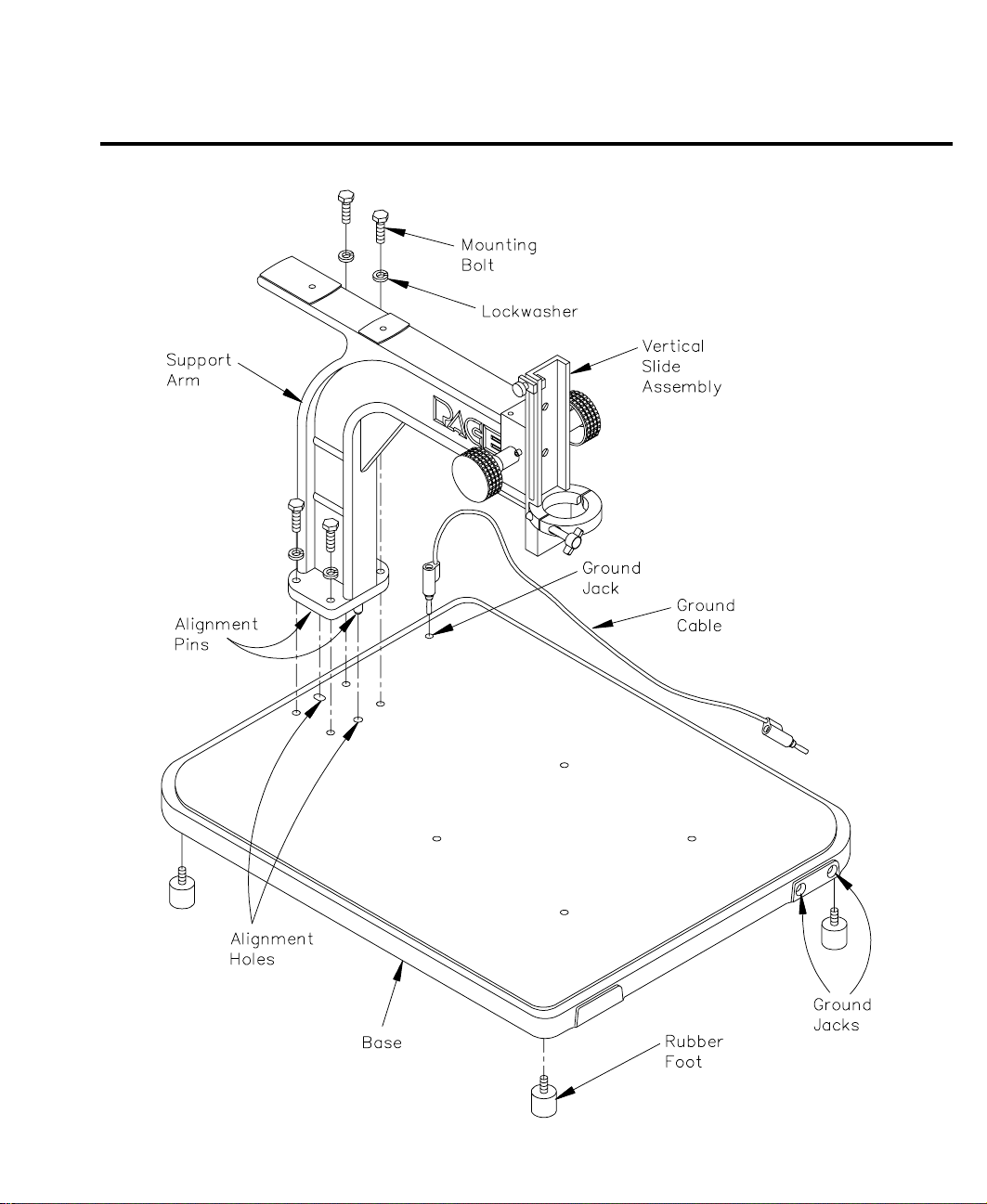
Advanced Placement Platform .............................................................................................................................. 4
Installation ................................................................................................................................................... 4
Operation ..................................................................................................................................................... 4
Vertical Slide Assembly ......................................................................................................................... 4
Ground Cable ......................................................................................................................................... 5
Fine Adjustment Table ........................................................................................................................... 6
ThermoFlo Handpiece ........................................................................................................................................... 8
Installation ................................................................................................................................................... 8
Operation ..................................................................................................................................................... 9
Standard Board Holder ........................................................................................................................................ 10
Installation ................................................................................................................................................. 10
Operation ................................................................................................................................................... 10
Heat Wave Interface ............................................................................................................................................. 12
Installation ................................................................................................................................................. 12
Operation ................................................................................................................................................... 12
Fiber Optic Lighting Attachment ........................................................................................................................ 13
Installation ................................................................................................................................................. 13
Operation ................................................................................................................................................... 13
Fume Extraction Ready Attachment.................................................................................................................... 14
Installation ................................................................................................................................................. 14
Operation ................................................................................................................................................... 15
Vision Systems ..................................................................................................................................................... 16
Introduction ............................................................................................................................................... 16
Precision Swivel ........................................................................................................................................ 16
Installation ........................................................................................................................................... 16
Operation.............................................................................................................................................. 17
Lens Vision Attachment ............................................................................................................................ 18
Installation ........................................................................................................................................... 18
Operation.............................................................................................................................................. 19
Camera Vision Attachment ....................................................................................................................... 20
Installation ........................................................................................................................................... 20
Operation.............................................................................................................................................. 21
Packing Lists ........................................................................................................................................................ 22
Systems ...................................................................................................................................................... 22
Optional Accessories ................................................................................................................................. 26

1
Introduction
This manual will provide you with the information necessary to properly install, operate and maintain all of the
available accessories (except Thermocouple Meter & Large Board Holder) for the PACE ThermoFlo systems.
Detailed installation instructions are provided for each available accessory. Currently available accessories are:
Work Platform Advanced Placement Platform
Heat Wave Preheating System Large Board Holder
Lens Vision Attachment Camera Vision Attachment
Fume Extraction "Ready" Attachment Thermocouple Meter (instructions supplied separately)
All ThermoFlo accessories are very easy to operate. Easy to understand guidelines are given for the operation of
each accessory (except Heat Wave & Large Board Holder). The Heat Wave and Large Board Holder are shipped
with separate manuals specific to that system/accessory only.

2
Installation
The Work Platform is provided with each TF 500 ThermoFlo System.
Use the following instructions and accompanying illustrations as a guide to assemble the Work Platform.
Work Platform
1. Place the Base upside down on a work surface and install the 4 Rubber Feet (with built-in screws) at
the corners of the Base.
2. Turn the Base over and position as shown.
3. There are 2 Alignment Pins located on the bottom of the Support Arm. Insert the 2 Alignment Pins
fully into the 2 Alignment Holes in the Base.
4. Install the 4 Mounting Bolts and Lock Washers. Tighten each bolt to secure the Support Arm to the
Base.
5. Insert one end of the supplied Ground Cable into the Base as shown or into either of the 2 Groun Jacks
at the front, right side of the Base.
Operation
Ground Cable
The Ground Cable is supplied to provide a connection to the Work Platform as a part of your static control
program.
Slide Assembly
The Vertical Slide Assembly holds the ThermoFlo handpiece in a vertical position for precise component
removal and installation operations. The handpiece is installed vertical to the work platform base; the bottom
edge of any installed nozzle (except Curved, Single Jet) is horizontal to any PCB (installed on a board holder)
on the Work Platform. Refer to the Handpiece Installation procedure to properly install the handpiece.
Simply rotate either of the Vertical Control Knobs to raise or lower an installed ThermoFlo handpiece (with
attached nozzle). Refer to "ThermoFlo Handpiece" "Operation" for additional information

3
Work Platform

4
Advanced Placement Platform
Installation
The Advanced Placement Platform (including Fine Adjustment Table) is provided with each TF 700 ThermoFlo
System. Use the following instructions and accompanying illustrations as a guide to assemble the Advanced
Placement Platform.
1. Place the Base upside down on a work surface and install the 4 Rubber Feet (with built-in screws) at
the corners of the Base.
2. Turn the Base over and position as shown.
3. There are 2 Alignment Pins located on the bottom of the Spacer. Insert the 2 Alignment Pins fully into
the 2 Alignment Holes in the Base.
4. There are 2 Alignment Pins located on the bottom of the Support Arm. Insert the 2 Alignment Pins
fully into the 2 Alignment Holes in the Spacer.
5. Install the 4 long Mounting Bolts and Lock Washers. Tighten each bolt to secure the Support Arm and
Spacer to the Base.
6. Place the Fine Adjustment Table in position on the Base. Align the 4 threaded Mounting Holes in the
center of the Base with the 4 Mounting Holes of the Fine Adjustment Table.
7. Secure FineAdjustment Table to the Base using the 4 short Mounting Bolts, Lockwashers & Flat Washers.
8. The 4 mounting screws that secure the ends of the 2 metal slide rods in position together may loosen
during shipment. Loosen all 4 mounting screws and perform the following procedure.
a) Move the Clamp Assemblies to the ends of the metal slide rods.
b) Move the metal slide rods to their Right side limit and tighten the 2 mounting screws on the Left
side ends of the metal slide rods. NOTE: You may need to loosen the X-Axis Lock.
c) Move the metal slide rods to their Left side limit and tighten the 2 mounting screws on the Right
side ends of the metal slide rods.
9. Insert one end of the supplied Ground Cable into the Base as shown or into either of the 2 Ground
Jacks at the front, right side of the Base.
10. Install the Y-Axis Stops into the Clamp Assemblies as shown. One of the Y-Axis Stops has a longer
curved "L" section than the other. This larger stop should be installed onto the left side of the Fine
Adjustment Table (facing as shown in illustration).
Operation
Vertical Slide Assembly
The Vertical Slide Assembly holds the ThermoFlo handpiece in a vertical position for precise component removal and
installation operations. Refer to the Handpiece Installation procedure to properly install the handpiece.
Simply rotate either of the Vertical Control Knobs to raise or lower an installed ThermoFlo handpiece (with
attached nozzle). Refer to "ThermoFlo Handpiece" "Operation" for additional information.

5
Ground Cable
The Ground Cable is supplied to provide a connection to the Work Platform as a part of your static control program.
Advanced Placement Platform

6
Fine Adjustment Work Platform
Fine Adjustment Table
The Fine Adjustment Table facilitates the installation of fine pitch SMT components. The table can hold your PCB
(up to 45.7cm X 45.7cm (18" X 18")) assemblies in position for rework. Fine adjustment x & y axis controls allow
easy component to land pattern alignment. Following is a description of the features. Refer to the illustration.
Parts Identification
À
PCB Clamp Assembly (2) - Holds PCB assembly on Fine Adjustment Table.
Á
Clamp Assembly Locks (2 on each Clamp Asembly) - Locks PCB in place preventing X-axis (side to
side) movement along the 2 metal slide rods. Two locks on each PCB Clamp Assembly must be fully
depressed to allow clamp movement along the slide rods.
Â
Y-Axis Fine Adjust Control - Allows fine adjustment of Y-Axis (front to back) table position.
Ã
X-Axis Fine Adjust Control - Allows fine adjustment of X-Axis (side to side) table position.
Ä
Y-Axis Stop (2) - Memory retention feature allows Y (front to back) directional stop reference for
repeatable PCB positioning.
Å
Y-Axis Locks - Locks Y-Axis Stops in place.
Æ
X-Axis Lock - Locks the metal slide rods in position to prevent X-Axis (side to side) movement.
Ç
Theta Lock - Locks table in position to prevent Theta Rotation.
Operation
1. Install the PCB to be repaired/reworked in the following manner.
a) Press the 2 Clamp Assembly locks on each PCB Clamp Assembly. Adjust the spacing of the 2
PCB Clamp Assemblies to the size of the PCB.
b) Orient the PCB as desired and insert side edges into the "V" grooved slot at the top of each PCB
Clamp Assembly. Slide PCB into clamp assemblies.
c) Adjust the PCB Clamp Assembly on the Right side of the table toward the PCB to apply a slight
spring pressure. Depress item
Á
Clamp Assembly Lock to release Clamp Assembly
2. Adjust the coarse center position of the PCB rework area relative to the ThermoFlo handpiece and
Nozzle in the following manner:
a) Lower the Nozzle to a position just above the PCB.
b) Position PCB in PCB Clamp Assemblies (item
À
) with rework area centered (front to back).
c) Turn the X-Axis Lock knob (item
±
) counterclockwise to free side to side movement of the metal
slide rods (and PCB). Move metal slide rods to position component rework area beneath
ThermoFlo handpiece and Nozzle. Turn the X-Axis Lock knob clockwise to lock in position.
d) Repeat 2a and 2b as necessary to center component rework area under Nozzle.

7
Fine Adjustment Work Platform
e) Turn the Theta Lock knob (item
Ç
) counterclockwise to loosen. Grasp the ends of the metal slide
rods; push one end while pulling the other to rotate table. Rotate table until component/land
pattern is square to nozzle. Turn Theta Lock knob clockwise to lock table in position.
d) Adjust the Y-Axis Stops if desired. Loosen (turn knobs counterclockwise) the 2 Y-Axis Locks
(item
Å
) and position the raised portion of the stops to contact the back edge of the PCB. Lock in
position with the Y-Axis Locks.
3. Fine adjust the position of the component to be removed to the nozzle or the component being placed
to the PCB land pattern in the following manner.
a) Turn the X-Axis Lock knob (item
±
) fully clockwise to lock metal slide rods in position.
b) Adjust table side to side position using the X-Axis Fine Adjust Control (item
Ã
).
c) Adjust table front to back position using the Y-Axis Fine Adjust Control (item
Â
).
d) Adjust Theta Rotation as necessary (see step 2e).

8
ThermoFlo Handpiece
Installation
NOTE
If the Fiber Optic Lighting Attachment or any of the Vision Attachments
(Lens or Camera) have been purchased, they should be installed before
performing the following procedure.
1. Unscrew the Plastic Heat Shield (marked "HOT")
from the ThermoFlo handpiece and set aside.
2. Install the metal Swivel Ring (part number 1321-
0320) onto the ThermoFlo handpiece.
3. Turn the Locking Knob counterclockwise several
turns to release the Clamping Socket.
4. Pull the Locking Knob forward. The Clamping
Socket will swing open at the knob.
5. Place the ThermoFlo handpiece, positioned at an
angle with the heater down, through the center of
the Clamping Socket.
6. The Clamping Socket and the Swivel Ring (on
handpiece) form a ball and socket attachment
mechanism. Slide the Swivel Ring into the
Clamping Socket.
7. Straighten the ThermoFlo handpiece up into a
vertical position. Ensure that the Swivel Ring
remains inside the Clamping Socket.
8. Push the Locking Knob and turn clockwise to
secure the ThermoFlo handpiece in position.

9
ThermoFlo Handpiece
Operation
The ThermoFlo handpiece can be easily raised or lowered
using either of the Height Adjustment Knobs.
To provide repeatable clearance of an attached nozzle
assembly relative the the surface of PCB assembly (Nozzle-
to-PCB clearance), do the following:
1. Loosen the Locking Knob. The Clearance
Limiter Assembly will now fall down against the
Stop.
2. Lower the handpiece to the desired distance of
Nozzle-to-PCB clearance using the Height
Adjustment Knobs.
3. Ensure contact between the Clearance Limiter
Assembly and the Stop. Tighten the Clearance
Limiter Locking Knob to secure the Clearance
Limiter Assembly in position on the Vertical
Slide.

10
Standard Board Holder
Installation
This accessory (part number 6018-0098) is provided with each TF 500 ThermoFlo System. You can use this
accessory to hold your PCB (up to 20.3 cm X 20.3 cm (8" X 8") size) assemblies in position for rework. If you are
using a Heat Wave Preheating System, it is not necessary to assemble this accessory; use the board holder on the Heat
Wave.
Use the following instructions and accompanying illustrations as a guide to assemble the standard Board Holder.
1. Place the Base (item
´
) upside down on a work surface and install the 4 Rubber Feet (item
É
) using
the 4 Mounting Screws (item 11 ).
2. Turn the Base over and position as shown.
3. Mount the Large Bracket (item
¬
) to the left side of the Base (item
°
) using 2 Mounting Screws (item
).
NOTE
There are mounting holes at 2 different heights on each of the supplied
brackets. Usetheholeswhich providethecorrect heightforusewithyour
PCB assemblies.
4. Place the Long Holding Clamp (item
¯
) in position on the Large Bracket (item
¬
). Secure clamp in
position using a Locking Screw (item
®
) and Flat Washer (item
³
).
5. Install the Leveling Screw (item
²
) Adjust Leveling Screw until its end just touches the bottom of the
Long Holding Clamp (item
¯
).
6. Mount the Small Bracket (item
°
) to the right side of the Base (item
´
) using 2 Mounting Screws
(item
).
7. Place the Short Holding Clamp (item
±
) in position on the Small Bracket (item
°
). Secure the clamp
in position using the Locking Screw (item
®
) with Flat Washer (item
³
).
Operation
To install a PCB assembly, simply adjust the holding clamps as necessary, place the PCB in the “V” grooves on
the clamps and tighten the Locking Screws to secure in position.
Position the Board Holder with the component rework area directly beneath the ThermoFlo handpiece.
Move the PCB or Board Holder as necessary for proper component-to-nozzle alignment.

11
Standard Board Holder

12
Installation
An interface cable must be installed when using the HS 200 Heat Wave system with the ThermoFlo. If an
Advanced Placement Platform has been purchased, an adapter plate must be installed on the bottom of the Heat
Wave heater unit to allow mounting onto the Fine Adjustment Table.
1. The Heat Wave Interface Cable (part number
1332-0187) connects the ThermoFlo Unit to the
Heat Wave power source to provide on/off
control of the pump assembly in the Heat Wave.
Connect the cable between the Heat Wave
connector on the rear panel of the ThermoFlo
Unit and the like connector on the rear panel of
the Heat Wave power source.
Heat Wave Interface
2. If you have purchased a Fine Adjustment Work Platform, install the enclosed Adapter Plate onto the
bottom of the Heat Wave Heater Unit using the 4 mounting screws supplied with the plate. Place the
Heat Wave Heater Unit on Fine Ajustment Table, inserting the 4 pins on the Adapter Plate into the 4
pin holes on the table. Refer to illustrations.
Operation
The Heat Wave Preheating System can be used at any time in conjunction with the ThermoFlo but the Heat Wave
motor pump is controlled by the ThermoFlo unit in the Program Mode only. The stored parameters of the Profile
in use will control activation of the motor pump. The temperature of the Heat Wave is not set or controlled by the
ThermoFlo. The temperature must always be set on the Heat Wave power source.

13
Installation
Use the following instructions and accompanying illustrations as
a guide to assemble the Fiber Optic Lighting Attachment.
1. Orient the Light Bracket as shown on the Support
Arm.
2. Install the 2 enclosed Mounting Screws to secure
the Light Bracket in position on the Support Arm.
3. Place the Light Power Supply in position on the
Light Bracket. The 4 rubber feet on the bottom of
the power supply fit in the punched holes at the
corners of the bracket.
4. Install the Goose Neck Assembly onto the Light
Power Supply as shown. Secure in position with
the Locking Screw.
5. Plug the female end of the enclosed power cord
into the power receptacle on the rear panel of the
Light Power Source.
6. Plug the male end of the power cord into the house
AC supply.
Operation
1. Turn the power switch(on Light Power Supply
front panel) to the On position.
2. Position both necks of the Goose Neck Assembly
for best application of light to the workpiece.
3. Adjust the light intensity control knob (on Light
Power Supply front panel) for best light
brightness.
Replacement Lamp (Light Power Supply) - PACE Part
Number 1165-0027
Fiber Optic Lighting Attachment
For complete information on operation, servicing and
replacement parts of the VL405 Light Power Supply,
refer to the enclosed Operation Manual.

14
Installation
This Kit (part number 6018-0105) allows the user to easily connect a 7.6mm (3 inch) fume extraction hose to the
Work Platform. Use the following instructions and accompanying illustrations as a guide to assemble the Fume
Extraction Ready Attachment.
1. Install the Hose Connector (item
¬
) onto the Support Arm as shown. Install the Height Locking Knob
(item
®
, the shortest of the 2 knobs supplied) through the slot in the Hose Connector and into either of
the 2 mounting holes in the Support Arm (see Rear View on illustration). Tighten the Height Locking
Knob(item
®
) to secure the Hose Connector in position.
NOTE
The2mountingholesoffertheuserawiderangeofheightadjustment. For
lower height adjustments, use the lower mounting hole;for greater height
requirements, use the upper mounting hole.
Fume Extraction Ready Attachment

15
Fume Extraction Ready Attachment
2. Install the Tube Locking Knob (item
¯
) loosely into its mounting hole.
3. Slide the straight end of the Tube (item
) into its mounting hole on the Hose Connector.
4. Adjust the Tube (item
) in position where the straight end is flush with the rear of the Hose
Connector (item
¬
) and the angled end is vertical to the Work Platform.
5. Tighten the Tube Locking Knob (item
¯
) to secure the Tube (item
) in position.
6. Connect a 7.6mm (3 inch) diameter, flexible air hose (not supplied) between the Hose Connector (item
¬
) and your fume extraction system.
Operation
1. Place a PCB assembly
(mounted on board holder,
fine adjustment table or
Heat Wave) in position on
the work platform.
2. Adjust the position of the
Tube with its angled end
aligned next to and facing
the PCB.
3. Position the height of the
Tube slightly above the
PCB by adjusting the height
of the Hose Connector.
4. Reposition the Tube as
necessary during rework
operations to provide
optimal fume extraction.

16
Introduction
The following procedures detail the steps required to install and operate any of the ThermoFlo vision accessories.
The Precision Swivel is supplied with each vision system purchased. Install the Precision Swivel and then install
your Lens Vision or Camera Vision Attachment using the applicable procedure.
Precision Swivel
Installation
Installation of this accessory is required before installing a Lens Vision or Camera Vision Attachment. . Use the
following instructions and accompanying illustrations as a guide to install the Precision Swivel.
Vision Systems
1. The Precision Swivel is supplied with its 2 Mounting Screws secured with 2 hex nuts to hold the
Spacer in place during shipment. Remove the 2 hex nuts and hold the Spacer, Precision Swivel and
Mounting Screws together.
2. Ensure that the Support Bracket is positioned as shown, opposite (180° from) the Mounting Screws. If
not, turn the Precision Swivel to place the Support Bracket in the proper position.
3. Place the Precision Swivel (with Spacer) in position on the Vertical Slide as shown with the 2
Mounting Screws aligned with the 2 mounting holes on the Vertical Slide.
4. Insert the 2 Mounting Screws into the 2 mounting holes on the Vertical Slide. Tighten the screws to
secure the Precision Swivel on the Vertical Slide.
5. Move the Vertical Slide up and down through its full range of travel to ensurefree movement. If the
Clearance Limiter Assembly Locking Knob hits the Precision Swivel, loosen the 2 Mounting Screws
and align the Precision Swivel to clear the Locking Knob. Tighten Mounting Screws to secure in
position.
Table of contents