PaceMaster Gold Indoor Cycle User manual
1
PaceMaster
GoldIndoorCycle
OWNER’SMANUAL
Aerobics Inc., 34 Fairfield Place West Caldwell, NJ 07006, (973) 276-9700
www.pacemaster.com
Part#ICGold Rev.12/21/07

2
TABLE OF CONTENTS
INTRODUCTION 3
IMPORTANT SAFETY INSTRUCTIONS 4
ASSEMBLY INSTRUCTIONS 5-10
Installation Requirements 5
Unpacking Your Indoor Cycle 5
Tools Required forAssembly 5
BoxContents 6
Assembling Your Indoor Cycle 7-10
OPERATING INSTRUCTIONS 11-14
Seat Height and PositionAdjustment 11-12
Handlebar Height and PositionAdjustment 13
ToeStrapAdjustment 14
ResistanceAdjustment 14
PREVENTATIVE MAINTENANCE 15
LIFETIME LIMITED WARRANTY 15
GOLD INDOOR CYCLE EXPLODED PARTS DIAGRAM 16
GOLD INDOOR CYCLE TECHNICAL SPECIFICATIONS 17

3
INTRODUCTION
Congratulations and thank you for choosing PaceMaster – your partner in achieving your fitness goals and
mastering your well-being.
PaceMaster’s superior components and US design ensure we produce equipment of the highest quality while
also offering excellent value for your dollar. PaceMaster products have consistently received praise from a wide
range of nationally recognized publications.
To get the most from your PaceMaster, please read this owner’s manual carefully before starting to use this
piece of exercise equipment.The manual contains important information about the assembly, operation and
maintenance of the machine.
Please ensure you read and fully understand all safety information. DANGER, CAUTION, or
WARNING indicates important safety warnings throughout the manual. Failure to read and understand
these warnings may result in personal injury or damage to your Indoor Cycle.
Tip indicates a useful suggestion when installing, assembling or using your Indoor Cycle.
Please take the time to familiarize yourself with the range of functions available. This will help you work with
your PaceMaster Indoor Cycle for maximum efficiency to achieve your fitness goals and master your well-being.
We wish you an enjoyable and rewarding partnership with your PaceMaster Indoor Cycle.
The PaceMaster Gold Indoor Cycle is designed for home use only.

4
IMPORTANT SAFETY INSTRUCTIONS
Read these instructions before using your Indoor Cycle
CAUTION: Before starting any exercise program, contact your personal physician and have a complete physical. This is
highly recommended if you have not been on a regular exercise program within the last year, or are over 35 years of age, or are
overweight.
CAUTION: If at any time during your exercise program you find theexercise abnormally difficult or you encounter dizziness, feel
faint, experience chest pains, feel as if your heart may be skipping beats, you experience forced heavy breathing after minimal
exercise or severe pain in your legs,ankles, knees, etc. STOPEXERCISING and consult your physician.
WARNING: To reduce the risk of injury:
•Your PaceMaster Indoor Cycle is not designed for use by children under the age of 18 without strict parental supervision.
•Close supervisionis necessary when the Indoor Cycle is used by or near children, disabled persons or pets.
•Use your PaceMaster Indoor Cycle only forits intended use as described in this manual. Donot use accessoriesor attachments
not recommended byAerobics, Inc.
•Never operate your PaceMaster Indoor Cycle if it is not operating properly, if it has been dropped or damaged or if it has been
immersed in water. Should any of these occur, contact your authorized PaceMaster retailer or service center for examination or
repair.
•Never drop or insert any object into any opening on the Indoor Cycle.
•Do not use outdoors.
•Position the Indoor Cycle with a minimum of 2 feetof clearance on all sides between the bike and any wall orobstruction.
•Do not allow anyone to reach under or be too near your PaceMaster while it is in use.
•Never allow more than one person on your PaceMaster Indoor Cycle at any time.
•Wear appropriate shoes and attire while exercising

5
ASSEMBLY INSTRUCTIONS
Installation Requirements
Your PaceMaster should be installed indoors on a flat, level surface. You must have a minimum of 2 feet of clearance on all sides
between the bike and any wall or obstruction.
TIP: If you are installing your PaceMaster on a carpeted surface, use an equipment mat or a scrap piece of carpet underneath the
Indoor Cycle to avoid soilingof the carpet. Deep pile carpet isnot recommended.
Unpacking Your Indoor Cycle Exercise Bike
On the next page is a listing of all the parts included in the box. Open the box and confirm that you have received all of the parts
indicated on page 6. If you are missing parts please contact yourAuthorized PaceMaster Dealer where you purchased your piece of
equipment.
Tools Required forAssembly
•4 mmAllen Wrench
•13 mm Wrench
•14 mm Wrench
•15 mm Wrench
6
Box Contents

7
Indoor CycleAssembly Summary

8
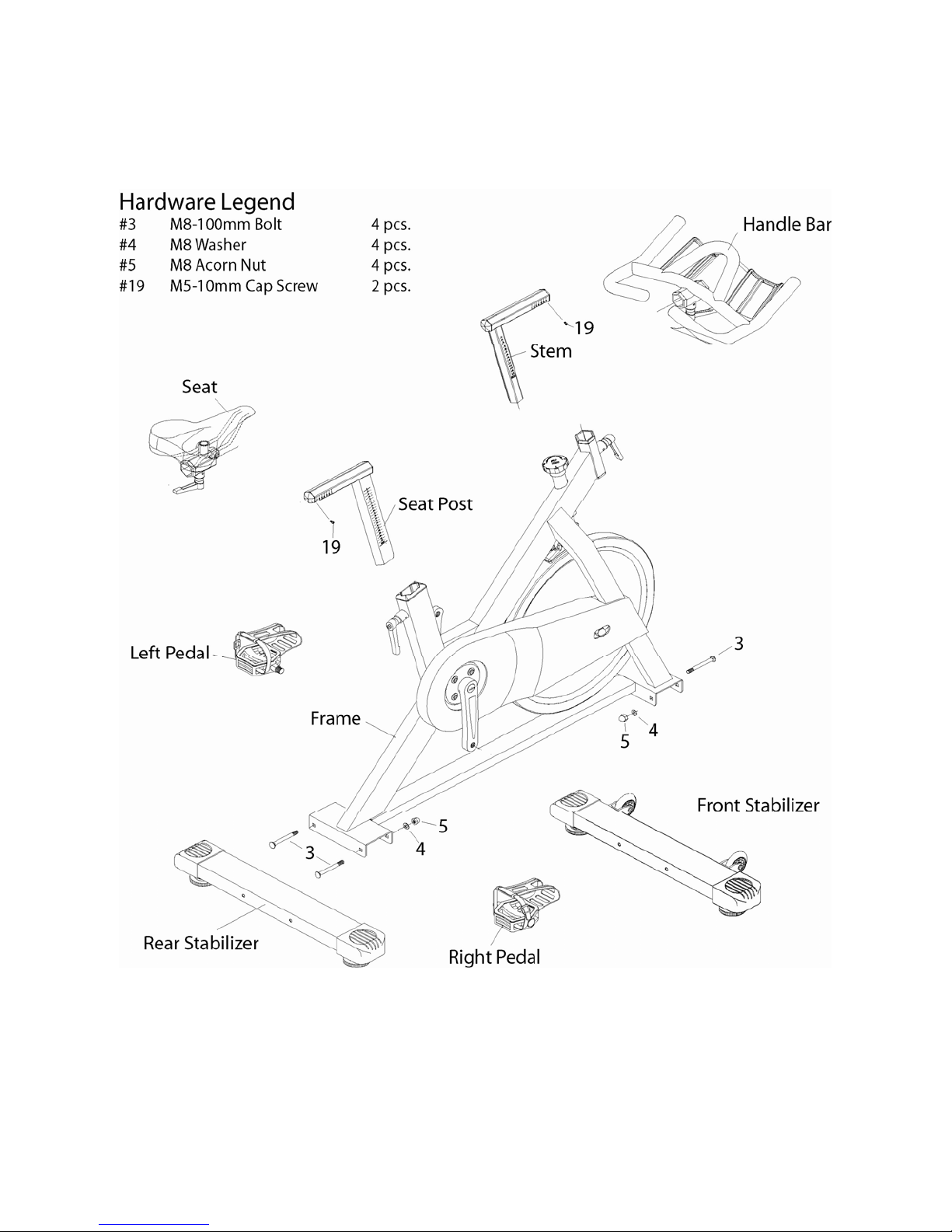
1.Assemble the Front Stabilizer
2.Assemble the Rear Stabilizer
STEP 1:
As shown to the Right, attach the Front Stabilizer
(6) to the Frame (1) with Bolts (3), Washers (4)
andAcorn Nuts (5), then tighten the nut (5) with a
13mm wrench.
Note: The front Stabilizer (6) is the one that
has the WHEELS ON IT, AND the wheels MUST
be towards the front.
STEP 2:
As shown to the Right, attach the Rear Stabilizer
(2) to the Frame (1) with Bolts (3), Washers (4)
andAcorn Nuts (5), then tighten the nut (5) with
a 13mm wrench.
Step 2
Step 1
9
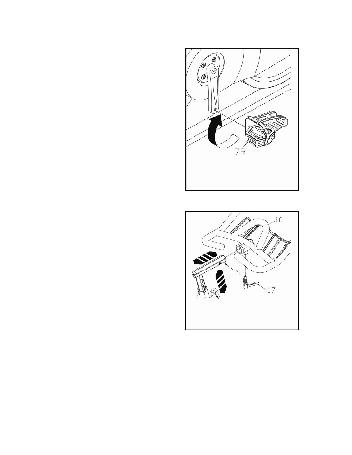
3. Install the Pedals
4. Install the Handle Bar
Step4
STEP 3:
The pedals are stamped on the threaded end of the
axle with the letter “R” and “L” for Right and Left
respectively. Right and Left sides are determined as
you would use the indoor cycle. Install the Right
pedal on the Right crank arm using a 15 mm wrench.
Install the Left pedal on the Left crank arm using a 15
mm wrench. NOTE: The Left pedal is reverse
thread (you must turn it counter-clockwise to
tighten it).
STEP 4:
Remove set screw (19), slide the Handle bar
assembly (10) on to the handle bar stem.
Tighten the adjustment knob (17) after positioning
the handle bar. Install set screw (19) as shown
to the ri
g
ht.
Step 3
10
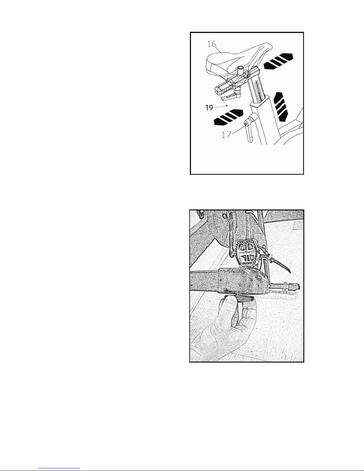
5. Install the Seat
6. Leveling the Indoor Cycle
Step5
STEP 5:
Remove set screw (19), slide the Seatassembly (16) on to the
seat post as shown to the right. Install adjustment knob (17)
and tighten after positioning the seat. Install set screw (19)
as shown to the right.
STEP 6:
It is important that you level your spin bike before use. There
are 2 adjustable leveling feet on the rear stabilizer. If your
Gold Indoor Cycle is not sitting with ALLfour of the feet in
contact with the floor, use the leveling feet to make the
necessary adjustments.
Step6
Table of contents
Other PaceMaster Exercise Bike manuals


 Service manual")


