Pacific Antenna Electret Series User manual

Pacific Antenna Electret Microphone Kit
Parts Included:
1 –1/2” x 4” long Blue PEX tube
1 – 5/8” I.D. vinyl tube cap
1 – oam microphone cover
1 – 4-40 brass nut
1 – 4-40 x 1/2” long flat head s.s. screw
1 – #4 x 1/16” thick nylon washer
1 – S1, pushbutton switch
1 – Electret microphone element
1 – 2 cond. shielded wire, with molded 3.5mm stereo plug
1 – C1, .001u capacitor
1 – 1/4w resistor, any value, only the wire is used –
1 – PCB
Specifications:
Sensitivity: 44±(0dB=1V/Pa,1KHZ)
Output impedance: 2.2KΩ(Max)
requency Range: ~70-20KHz
Operating Voltage: 3 V
Current Consumption: 0.5mA(Max)
Assembly
ElectretMic20180125 1

Prepare the tube:
Print out the drill template found on the last page of this manual set to full size or 100% on your printer.
Verify that the template is 4 inches (101.6mm) long. If not ad ust your printer scaling so that it is 4 inches when
printed.
Print the template and cut out. This will be used to mark the holes for drilling in the microphone tube.
Wrap the template around the tube and secure in place with tape.
Using a center punch, nail or other sharp ob ect, mark the center of the holes in the tube.
Remove the template and drill two holes of 3/16 inch (~4.8mm) diameter through only one side of the tube.
Assemble the circuit board:
Secure the brass nut to the circuit board using the supplied 4-40 screw. The screw head should be on the bottom of
the board and the brass nut on top of the bare circular pad.
Carefully tighten the screw so that the brass screw is in contact with the pad and centered.
Solder around the edges of the brass screw to secure it to the pad.
Remove the screw and attach the nylon spacer centered on the top of the brass screw with superglue.
Use care not to get glue on the threads of the nut and be sure the spacer is centered over the hole in the nut.
Hint: After the glue is applied, you can heat the brass nut a bit gently with a soldering iron to cure the adhesive.
Insert and solder switch S1 on the top of the board making sure to fully seat it against the board before soldering.
Insert and solder capacitor C1 in the location marked on the board.
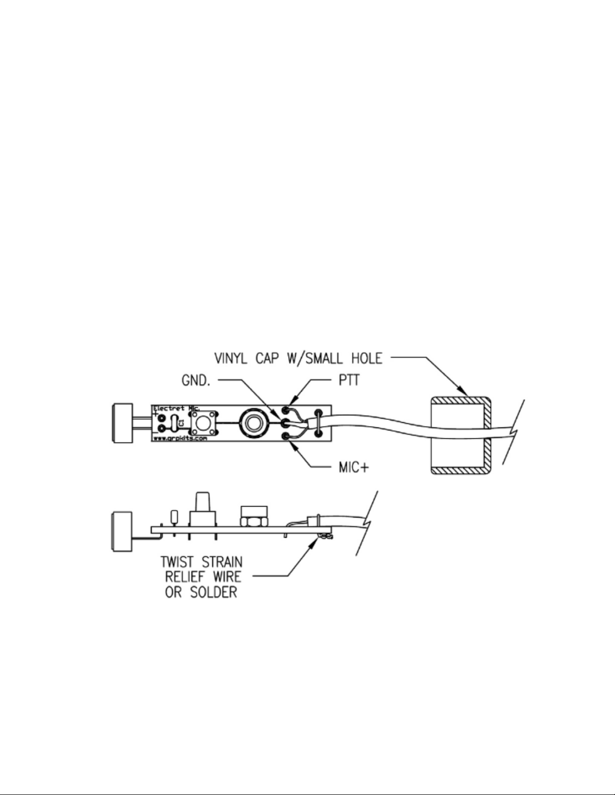
Install the microphone element as shown in the below, making sure to orient the microphone element as shown for
correct polarity with the + side of the mic connecting to the hole marked + on the board.
onnect the able:
ElectretMic20180125 2

Prepare the vinyl cap by creating a hole in the center for the cable to pass through. This can be done with a punch,
or other tool or by melding carefully with a soldering iron tip. The hole needs to be approximately 1/8 inch for the
cable.
First, pass the cable end through the hole in the cap and prepare for connecting to the board by stripping the outer
acket from approximately 1/2” of the cable.
Double check that the cable passes through the cap as shown in the drawing below
Strip and tin about 1/4” of each of the two leads and tin 1/4” of the bare braid.
Check with an ohmeter to see which of the two wires connect to which part of the 3.5mm plug. One wire will go to
each section, Tip or ring Ring and the bare braid connects to the shell or base.
You will need to wire correctly for your particular application so double check which part of the 3.5mm plug will
need to connect to the PTT and MIC before soldering to the board. The bare braid goes to the center (GND) pad.
Once soldered, use a section of resistor lead or similar bare wire to strain relief the cable.
Loop the wire through the holes as shown below, pull tightly and twist and/or solder to the board to secure the
cable. Use care not to overheat the wire as it will melt into the cable a bit during soldering.
Trim all component leads close to the bottom of the circuit board.
This completes the assembly of the microphone circuit board.
Wiring heck:
ElectretMic20180125 3

Check the connections at the 3.5mm plug.
You should see continuity between the connector base and the connection chosen for PTT when you press the
switch.
You should also see approximately 1.5K ohms from the base to the connection used for the Microphone.
Assemble the Microphone:
Insert the circuit board into the microphone tube as shown below. You may need to slightly depress the switch to
allow the board to enter the tube.
Slide the board into the tube until the switch is aligned and snaps into the hole nearest to the opposite end of the
tube.
Insert the screw and tighten to secure the circuit board within the tube as shown below.
To improve audio response, it is also recommended to add some material such as a cotton ball, soft fabric or foam
to fill the open space at the end of the microphone tube.
Slide the rubber cap up to cover the bottom end of the microphone.
ElectretMic20180125 4

To finish the microphone, install the included sponge foam microphone cover on the end of the tube where the
microphone element is located.
ongratulations, your microphone is now complete!
Using the microphone:
Electret microphones need a voltage bias to operate. This is supplied through the MIC+ lead either from your radio
or an external supply. A dropping resistor and blocking capacitor may be required if not included in your radio.
An example of how electret microphones are connected can be found here:
https://en.wikipedia.org/wiki/Electret_microphone
Another example is seen in the Bitx kit manual located here:
http://qrpkits.com/files/BITX20_Assembly_Manual.pdf
For support contact us by email: [email protected]
ElectretMic20180125 5

Drilling Template
The template should be 4 inches when printed. If not, ad ust the output size for your printer until it is correct.
ElectretMic20180125 6
Drill template
This manual suits for next models
1
Table of contents