Pacific Northwest Technologies Accuweigh PNT9700 User manual

1
Unplug the connector from the back of the meter before jump-starting,
battery-charging, or welding on the truck
ON-BOARD WEIGHING SYSTEMS
PNT9700 User’s Manual
Installation Calibration Operation
(Version 4.00)
Pacific Northwest Technologies
2
Do not use pencils or other sharp-pointed objects to press the meter’s keys.

3
Unplug the connector from the back of the meter before jump-starting,
battery-charging, or welding on the truck
ON-BOARD WEIGHING SYSTEMS
Contents
Chapter 1 Introduction................................................... 7
Chapter 2 Meter Setup................................................... 9
Starting the Meter Setup.........................................................9
Setting the Load Units...........................................................10
Setting the Grad Size............................................................11
Setting For Net Or Gross....................................................... 12
Chapter 3 Calibration ....................................................13
Entering the Empty Weight.................................................... 14
Entering the Loaded Weight ..................................................17
Advanced Calibration ............................................................20
Chapter 4 Operating the Meter ......................................23
Selecting the Weight-display Channel..................................... 23
Selecting the Auto-cycle Function........................................... 23
Changing the Auto-cycle Speed..............................................24
Recalling the Tare Weight .....................................................25
Recording the Cal Factor.......................................................26
Chapter 5 Troubleshooting............................................31
Chapter 6 Test Mode ....................................................37
Recording Test Numbers.......................................................38
Chapter 7 Installation....................................................41
Installing the Meter...............................................................41
Mounting the Transmitters ....................................................42
Routing the Signal cables......................................................42
Routing the Power Cable.......................................................43
Connecting the Cables ..........................................................43
Final Step ............................................................................44
4
Do not use pencils or other sharp-pointed objects to press the meter’s keys.
Chapter 8 Maintenance .................................................45
Daily Inspections...................................................................45
Weekly Inspections...............................................................45
Chapter 9 Special Operations.........................................47
Entering the Weight-to-go Limits............................................47
Setting For Weight-to-go .......................................................51
Setting the Transmitter Model................................................52
Chapter 10 Using Multiple Trailers ...................................55
Enabling the 2-channel ID Number.........................................55
Set 2-channel ID Number ......................................................56

5
Unplug the connector from the back of the meter before jump-starting,
battery-charging, or welding on the truck
ON-BOARD WEIGHING SYSTEMS
The PNT 9700 AccuWeigh digital on-board weighing system consists of
a digital meter, load cells, transmitters, and cables designed for logging
trucks. The meter is optimized to be used with PNTechnologies trans-
mitters and cables but will also function with other equipment.
Benefits of using the PNT 9700 include:
Flexibility to read individual axle weights
A reliable two-wire hookup between the transmitters and the meter
An extremely bright weight display, visible even in bright sunlight
Ability to calibrate the meter without having to have the truck load-
ed
A unique load-hold feature, useful when loading at several different
sites
Measurements in increments of 10, 20, 50, or 100 pounds or kilo-
grams
Internal software that can be updated to include the latest en-
hancements.
A modern on-board weighing systems consists of load cells to sense the
load’s weight, transmitters and cables to send the load-cell output to
the meter, and a meter to change the signals into information usable
by the operator.
Load cells are precision-machined high-strength steel beams with
strain gages bonded inside. The load cell is installed on the truck be-
tween the log load and the truck frame. When the logs are loaded on
the truck, the strain gages sense the weight of the logs and send a
small electrical signal to the meter by way of the transmitter.
The transmitter provides the voltage to the load cell to power the
strain gages. A signal voltage from the load cell is returned to the
transmitter where it is converted to a digital signal before being sent to
the PN9700 meter through the two-wire cable.
6
Do not use pencils or other sharp-pointed objects to press the meter’s keys.
The PNT 9700 meter receives the digital signal from the transmitter
and interprets and displays it as a weight in pounds or kilograms.
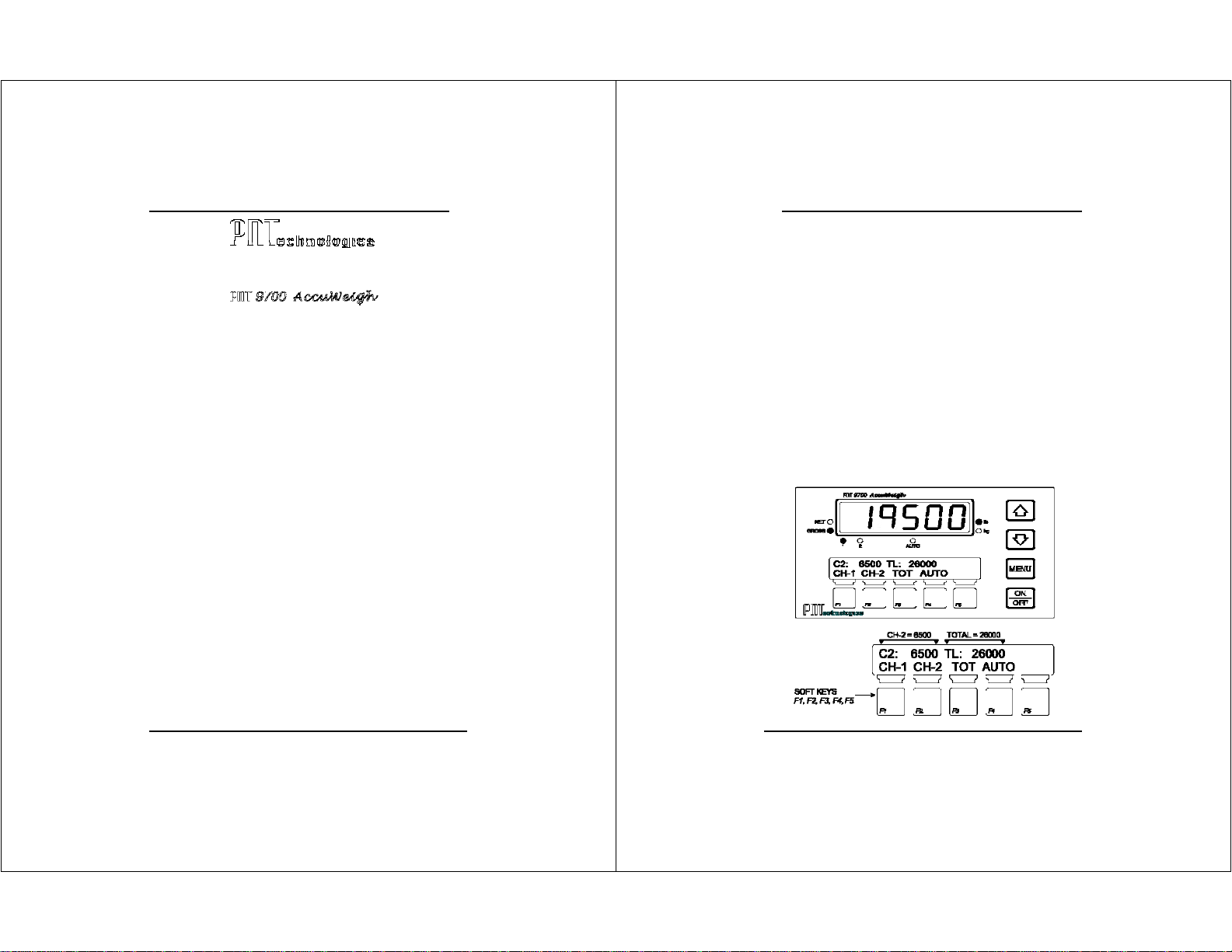
Two displays are used on the front of the meter. The top LED display
shows the weight of the load and can easily be switched between
truck, trailer, or total weight. The lower dot-matrix information dis-
play complements the top display by showing the two non-displayed
weights. For example, if the top LED display is set to show the truck
weight, the upper line of the information display will show the trailer
weight and the total weight.
When the meter is in either the calibration or setup modes, the upper
line of the information display will show a calibration or setup mes-
sage. The lower line will show the appropriate legend for the blue
“soft” keys, F1 through F5. The function of each of these keys
changes depending on the mode that the PNT 9700 is in. The labels
will change as various menus are selected during calibration or setup.
During normal operation, the keys will select:
CH-1 [F1] Channel 1 or truck weight
CH-2 [F2] Channel 2 or trailer weight
TOT [F3] Total weight
AUTO [F4] Autocycle between Ch 1, Ch 2, and Total

7
Unplug the connector from the back of the meter before jump-starting,
battery-charging, or welding on the truck
CHAPTER 1 INTRODUCTION
The PNT 9700 meter has two menus used for setup and calibration,
the FUNCTION MENU and the SETUP MENU.
The FUNCTION MENU is used to:
reset the empty weight
select a gross or net weight mode
select the preferred speed for the auto-cycle mode
enable or disable the load-hold feature
determine load-cell test numbers
recall the tare weight
record the test numbers
enable the meter for weight-to-go feature
The SETUP MENU is used to:
calibrate channel 1 or 2
enable the advanced calibration feature
select the different weight increments, commonly called
the grad size
select the proper weight unit, such as pounds or kilograms
record the cal factor
enter the weight-to-go limits
The ADVANCED SETUP MENU is used to:
enter the transmitter model
set the meter for multiple trailers
The following chapters guide you through the setup and calibration of
the meter. If a key on the right-hand side of the meter needs to be
pressed, a small drawing of the key will be shown, like this:.
Messages displayed in the upper line of
the information display will be shown in
the format as they would be seen in the
window and will be shown on the right-
hand side of the page, like the example
to the right of this paragraph.
8
Do not use pencils or other sharp-pointed objects to press the meter’s keys.
The labels for the five blue soft keys along the bottom of the
meter will be shown similarly in the bottom line of the
information display, immediately above the key, like the
example to the right of this paragraph.
INTRODUCTION

9
Unplug the connector from the back of the meter before jump-starting,
battery-charging, or welding on the truck
CHAPTER 2 METER SETUP
INTRODUCTION
This chapter will guide you through the meter setup prior to doing the
calibration. Questions to ask yourself are:
1. Will you want the weight display to show in pounds (lbs) or
kilograms (kgs)?
2. Do you want the weight shown in 10, 20, 50, or 100 lbs or kgs
increments (grad size)? Selecting 10 or 20 will give better
resolution but the display will appear unstable because the numbers
will fluctuate more frequently when the truck slightly moves. A grad
size of 50 is a good all-around selection.
3. Should the weights be shown as gross weight or net weight? Most
operators want the display to show gross weight so they can see the
same weight that any roadside platform scale or mill scale would
see.
STARTING THE METER SETUP
Turn on the meter by firmly pressing the key. The information
display will first show POWER ON and then show the meter model and
the software version. During this time, the meter is also performing an
internal self test which includes briefly lighting all of the small red
indicator lights. If the information display shows any error messages,
refer to Chapter 5,
Troubleshooting.
10
Do not use pencils or other sharp-pointed objects to press the meter’s keys.
SETTING THE LOAD UNITS (LB OR KG)
It is important to see if the meter is displaying weights in kilograms
(kg) or pounds (lb). Look at which of the small red LED lamps is on at
the right of the weight display, next to the lb or kg label. If not
correct, do the following:
1. Press the key for 5 seconds until
the information display shows
After releasing the key, the
information display will show
2. Press the or key to
select the UNITS menu.
3. Press the or key to select the desired unit.
4. Press the key to store the change.
5. When finished, press the key to exit the SETUP MENU.
METER SETUP

11
Unplug the connector from the back of the meter before jump-starting,
battery-charging, or welding on the truck
SETTING THE GRAD SIZE
The grad size, or graduation, allows the meter to display the load
weight in either 10, 20, 50, or 100 lb or kg increments.
1. Press the key for 5 seconds until
the information display shows
After releasing the key, the
information display will show
2. Press the or key to select
the GRAD SIZE menu.
3. If no change is desired, press the key.
4. If you want to change the grad size, press the key,
followed by the key.
5. Press the or key to select a grad size: 10, 20, 50, or 100.
6. Press the key to store the change. Press the key to
exit the SETUP MENU.
METER SETUP
12
Do not use pencils or other sharp-pointed objects to press the meter’s keys.
SETTING FOR NET OR GROSS
The NET weight refers to the weight of the load; it does not include
the weight of the truck and/or trailer. GROSS weight, however, refers
to the weight of both the load and the truck/trailer combination. Look
at which of the small red LED lamps is on at the left of the weight
display, next to the NET or GROSS label. If not correct, do following:
1. Press the key to get the
If you do not continue with the operation within 15 seconds, the
meter will reset to the normal weighing mode and you will need to
press the key again.
2. The information display will show
3. Press the key again to show
4. Press the key to select GROSS WEIGHT. The red
GROSSLED lamp will turn on.
5. Press the key to select NET WEIGHT. The red NET
LED lamp will turn on.
6. Press the key to exit the SETUP MENU.
METER SETUP

13
Unplug the connector from the back of the meter before jump-starting,
battery-charging, or welding on the truck
CHAPTER 3 CALIBRATION
INTRODUCTION
The calibration process allows you to fine tune your weighing system to
provide the greatest degree of accuracy. The accuracy of the PNT
9700 AccuWeigh, however, depends on the accuracy of the information
you provide. You will be required to have the weights of your truck
and trailer when they are empty (tare weight) and when they are
loaded (gross weight).
Find a certified platform scale of known accuracy, such as a state-
operated weight-enforcement highway scale or a mill scale. Have your
empty log truck and trailer weighed with the trailer down. Get the
truck weight (including the steer axle and the drive axles) and the
trailer weight. For future reference, record the weights here:
Truck (steer and drive axles): __________________ LB KG
Trailer (trailer axles): __________________ LB KG
Total weight: __________________ LB K G
Not all platform scales read the same, so try to use the same scales
whenever you need to recalibrate the meter or check the calibration.
Use the same scales for recording loaded weights that you used for
getting your empty weights.
14
Do not use pencils or other sharp-pointed objects to press the meter’s keys.
ENTERING THE EMPTY WEIGHT INTO THE METER
Before entering the empty weights into the meter, make sure the
meter display is set to GROSS (refer to Chapter 1,
Setting For Net Or
Gross Weight)
. Also, make sure the truck and trailer are empty and
the trailer is on the ground with the meter cable connected.
1. Press the key for 5 seconds
until the information display shows
2. After releasing the key, the
information display will show
and the weight display will show
3. To enter the truck empty weight,
press the or key until
the information display shows
4. Press the key.
The information display will briefly
(for about 4 seconds) show
It will then show
CALIBRATION

15
Unplug the connector from the back of the meter before jump-starting,
battery-charging, or welding on the truck
5. The last number of the weight display will be flashing, telling you
that number is ready to be changed.
To change the number’s value, press the or key.
To select a different number, press the or key.
6. When the number on the weight display matches your truck
(channel 1) empty weight, press the key to store the
weight in the meter’s memory.
The information display will briefly show
and then return to
and the weight display will show
7. To enter the trailer empty weight,
press the or key until
the information display shows
8. Press the key. The information
display will briefly show
CALIBRATION
16
Do not use pencils or other sharp-pointed objects to press the meter’s keys.
It will then show
9. The last number of the weight display will be flashing, telling you
that number is ready to be changed.
To change the number’s value, press the or key.
To select a different number, press the or key.
10. When the number on the weight display matches your trailer
(channel 2) empty weight, press the key to store the
weight in the meter’s memory.
The information display will show
then return to
11. At any time, you can exit the calibration process by pressing
the key.
The information display will briefly show
CALIBRATION

17
Unplug the connector from the back of the meter before jump-starting,
battery-charging, or welding on the truck
ENTERING THE LOADED WEIGHT INTO THE METER
The following steps can be completed only after having your loaded
truck weighed at a certified and accurate platform scale. The accuracy
of your meter will completely depend upon the accuracy of the platform
scale. For best results, use the same scales you used for getting your
empty weights.
The steps involved are similar to those used for entering the empty
weights.
1. Press the key for 5 seconds
until the information display shows
2. After releasing the key, the
information display will show
and the weight display will show
3. To enter the truck’s loaded weight,
press the or key until
the information display shows
4. Press the key. The information
display will briefly show
It will then show
CALIBRATION
18
Do not use pencils or other sharp-pointed objects to press the meter’s keys.
5. The last number of the weight display will be flashing, telling you
that number is ready to be changed.
To change the number’s value, press the or key.
To select a different number, press the or key.
6. When the number on the weight display matches your truck
(channel 1) loaded weight, press the key to store the
weight in the meter’s memory.
The information display will briefly show
and then return to
and the weight display will show
7. To enter the trailer’s loaded weight,
press the or key until
the information display shows
8. Press the key.
The information display will briefly show
CALIBRATION

19
Unplug the connector from the back of the meter before jump-starting,
battery-charging, or welding on the truck
It will then show
9. The last number of the weight display will be flashing, telling you
that number is ready to be changed.
To change the number’s value, press the or key.
To select a different number, press the or key.
10.When the number on the weight display matches your trailer’s
(channel 2) loaded weight, press the key to store the
weight in the meter’s memory.
The information display will show
then return to
11. At any time, you can exit the calibration process by pressing
the key.
The information display will briefly show
CALIBRATION
20
Do not use pencils or other sharp-pointed objects to press the meter’s keys.
ADVANCED CALIBRATION
Another way to enter the loaded weight into the meter is with the
advanced calibration feature. This method allows the calibration of
several trucks to be centrally controlled. The driver does not have to
enter the setup mode of the meter, even for calibration. After setting
in the tare weight, the driver need only record two sets of numbers:
1. the truck and trailer loaded weight shown by the platform
scale, and
2. the channel 1 and channel 2 weights recorded on the
PNT9700 while the truck is on the platform scale.
The following steps are used for the advanced calibration, which can
be done on an empty truck, if necessary.
1. Press the key for 5 seconds
until the information display shows
After releasing the key, the
information display will show
and the weight display will show
2. Press the or key until
the information display shows
3. Select the channel to calibrate by pressing
the key or the key.
For this example, we will assume
you selected
CALIBRATION

21
Unplug the connector from the back of the meter before jump-starting,
battery-charging, or welding on the truck
4. Enter the number that was earlier recorded as the number shown
on the meter’s weight display for channel 1 while sitting on the
platform scale. Change the numbers in the same manner as
then setting the original loaded-weight calibration (shown in the
previous section of this chapter). Press the key when
completed.
5. The information display will show
6. Enter the number that was earlier recorded as the legal truck
weight from the platform scale. Change the numbers in the
same manner as in Step 4, above.
Press the when completed.
7. The information display will show
Press the key to return to normal operation.
CALIBRATION
22
Do not use pencils or other sharp-pointed objects to press the meter’s keys.

23
Unplug the connector from the back of the meter before jump-starting,
battery-charging, or welding on the truck
CHAPTER 4 OPERATING THE METER
INTRODUCTION
Now that the meter is set up and calibrated, it will continuously
monitor the truck’s load. The operator can lock the weight display to
always show the truck or trailer weight or the total weight while
viewing the other two channels in the information-display window.
Auto-cycling can also be selected to continuously and automatically
switch the weight display between the three channels.
SELECTING THE WEIGHT DISPLAY CHANNEL
1. Press the key to have the red
LED weight-display window show the
channel 1 weight. The information
display will show the weight for
channel 2 and the total weight.
2. Pressing the key or the key will similarly change
both displays.
SELECTING THE AUTO-CYCLE FUNCTION
The auto-cycle function lets the meter continuously change the weight
display from the channel 1 weight to the channel 2 weight to the the
total weight, then repeats the cycle
1. Press the key to continuously
cycle the weight display through the
three channels.
24
Do not use pencils or other sharp-pointed objects to press the meter’s keys.
2. The weight-display window will
momentarily show
then switch to the appropriate weight. The red LED lamp labeled
AUTO will turn on and the LED lamps labeled 1and 2will
alternately turn on, depending on which channel is being
displayed.
3. To leave the AUTO CYCLE function,
press either the or key.
The weight display will then show
whichever channel you selected
and the information display will
show the other two weights.
CHANGING THE AUTO-CYCLE SPEED
The time that the meter dwells on each channel display when in auto
cycle can be selected by the operator. Three times are available:
SLOW 10seconds
MID 6seconds
FAST 3seconds
1. Press the to get the
If you do not continue with the operation within 15 seconds, the
meter will reset to the normal weighing mode and you will need to
press the key again.
2. The information display will show
3. Press the key two more times
and the information display will show
OPERATING THE METER

25
Unplug the connector from the back of the meter before jump-starting,
battery-charging, or welding on the truck
4. Press the appropriate key to select the desired time.
5. Press the key if you decide not to change the time. If no
keys are pressed within 15 seconds, the meter will return to
normal operation.
RECALLING THE TARE WEIGHT
During normal day-to-day operations, one or both of the channels
may slightly drift from the originally-set empty-weight (tare-weight)
calibration. Various reasons can explain a small drift, for example:
1. large changes in outdoor temperature from morning to mid-day,
2. dropping a log on the front or rear bunks,
3. mud or snow accumulations.
To recall the tare weight, perform the following steps:
1. Press the key to get the
If you do not continue with the operation within 15 seconds, the
meter will reset to the normal weighing mode and you will need to
press the key again.
2. The information display will show
Select the appropriate channel by pressing the key or
the key. The meter will return to the previously set tare
weight for the channel selected and will be ready for normal
operation.
OPERATING THE METER
26
Do not use pencils or other sharp-pointed objects to press the meter’s keys.
3. An error message may be shown
for 5 seconds in the information
display if the tare weight of channel 1,
for example, has drifted more than
3000 lbs
or 2500 kgs.
The display will change to show
and the weight display will return to the tare weight shown before
the attempted change.
RECORDING THE CAL FACTOR
The cal factor is a number related to the calibration of each channel of
the meter. Should you need to change meters, using the cal factor will
considerably speed the process. By entering into the new meter the
cal factors from the old meter, the new meter will have the same
calibration. Use the space below to record your meter’s cal factor.
Truck (channel 1) cal factor _________________________
Trailer (channel 2) cal factor _________________________
1. Press and hold the key
about 5 seconds until the
information display shows
2. After releasing the key,
the information display will show
OPERATING THE METER

27
Unplug the connector from the back of the meter before jump-starting,
battery-charging, or welding on the truck
and the weight display will show
3. To find the cal factor for the truck
(channel 1) channel, press the
or key until the
information display shows
4. Press the key.
The information display will show
5. The last number of the weight display will be flashing, telling you
that number is ready to be changed. If you are only recording the
number and not changing it, record it on the previous page and
then press the key.
6. If you are installing a replacement meter and want to enter the
truck (channel 1) channel cal factor from the previous meter,
press or to select the number for changing.
7. When the number on the weight display matches your truck
(channel 1) cal factor, press the key to store the cal factor
in the meter’s memory.
The information display will show
and then return to
OPERATING THE METER
28
Do not use pencils or other sharp-pointed objects to press the meter’s keys.
and the weight display will show
8. To find the cal factor for the trailer (channel 2) channel,
press the or key
until the information display shows
9. Press the key.
The information display will show
10. The last number of the weight display will be flashing, telling you
that number is ready to be changed. If you are only recording
the number and not changing it, record it on the previous page
andthen press the key.
11. If you are installing a replacement meter and want to enter the
trailer (channel 2) channel cal factor from the previous meter
press or key to select the number for changing.
12. To change the value of the number, press or key
13. When the number on the weight display matches your trailer
(channel 2) cal factor, press the key to store the cal factor
in the meter’s memory.
OPERATING THE METER

29
Unplug the connector from the back of the meter before jump-starting,
battery-charging, or welding on the truck
After recording or resetting the cal factor numbers, press
the key.
The information display will briefly
show
and then return to normal operation.
OPERATING THE METER
30
Do not use pencils or other sharp-pointed objects to press the meter’s keys.

31
Unplug the connector from the back of the meter before jump-starting,
battery-charging, or welding on the truck
CHAPTER 5 TROUBLESHOOTING
Troubleshooting is a systematic process of testing, identifying, and
eliminating areas of the weighing system that are causing problems or
malfunctions. The PNT9700 is designed to aid in troubleshooting by
providing error codes which identify problems. Many of the error codes
will show either channel 1, the truck channel, or channel 2, the trailer
channel, whichever is applicable.
The PNT9700 system has two wires going from each transmitter to
their respective load cells. One wire has a red band next to the load-
cell connector and is called the red side and the plain black wire, to
the other load cell, is called the black side. The PNT9700 will
sometimes refer to the red side or the black side in the error
messages.
An effective and easy troubleshooting method is called substitution.
For example, if the error message says the red side is defective, swap
the red and black wires at the load cells. If the error message remains
the same, then the trouble is with the wire. If the message changes
to say the black side is defective, then the load cell is the problem.
The same idea can be used with the channel 1 and channel 2 wires at
the back of the meter.
The weight display will show if there is a
problem with channel 1 or,
if channel 2 is not working, will be displayed.
Additional details to aid in troubleshooting will be shown in the
information display window.
The following sections will show how the error codes are displayed, list
the possible causes, and some troubleshooting hints.
32
Do not use pencils or other sharp-pointed objects to press the meter’s keys.
The red-banded wire may be
damaged between the load cell and
the channel 1 transmitter.
a. The load cell connected to the red-banded wire of channel 1 may
be defective.
b. Swap the two load-cell cables. If the message is the same, the red
-banded wire is damaged, possibly pinched or cut. If the message
changes to say the black side is defective, then the load cell is the
problem.
The black wire may be damaged
between the load cell and the
channel 1 transmitter.
a. The load cell connected to the black wire of channel 1 may be
defective.
b. Swap the two load-cell cables. If the message is the same, the
black wire is damaged, possibly pinched or cut. If the message
changes to say the red side is defective, then the load cell is the
problem.
These two are the same as the
channel 1 examples above except
they apply to channel 2
.
TROUBLESHOOTING

33
Unplug the connector from the back of the meter before jump-starting,
battery-charging, or welding on the truck
Channel 1 is not connected to its
transmitter.
a. The channel 1 wire may have been disconnected at the back of
the meter.
b. The channel 1 wire may be damaged between the channel 1
transmitter and the meter. Disconnect the channel 1 wires from
the meter. Connect the channel 2 * wires to the channel 1
terminals. If the message stays the same, the meter is defective.
If the message goes away and channel 1 works again, then the
wire is the problem. Check for a cut wire or a connector
unplugged.
*
Assuming channel 2 is working.
Channel 2 is not connected to its
transmitter.
a. The channel 2 wire may have been disconnected at the back of
the meter.
b. The channel 2 wire may be damaged between the channel 2
transmitter and the meter. Disconnect the channel 2 wires from
the meter. Connect the channel 1 * wires to the channel 2
terminals. If the message stays the same, the meter is defective.
If the message goes away and channel 2 works again, then the
wire is the problem. Check for a cut wire or a connector
unplugged.
*
Assuming channel 1 is working.
The difference between the original
empty weight and the current empty
weight is too
large for the
RECALL
EMPTY WEIGHT
command to
function. The difference is limited to
3000 lbs or 2500 kgs.
Check for other problems, such as:
a. bent or distorted load cell
b. damaged load-cell mounting
c. bent truck or trailer frame
d. defective load cell
TROUBLESHOOTING
34
Do not use pencils or other sharp-pointed objects to press the meter’s keys.
The channel 1 wires are shorted
together or shorted to the truck
frame.
a. Disconnect the channel 1 wires from the back of the meter. If the
error message remains, the meter is defective. If the message
goes away, check the channel 1 wire.
b. The channel 1 wires may be damaged between the load cell and
the transmitter or between the transmitter and the meter.
c. Check all wires for cuts or for pinched areas.
d. Check for worn insulation where the wire could be shorted to the
truck or trailer frame.
The channel 2 wires are shorted
together or shorted to the truck
frame.
a. Disconnect the channel 2 wires from the back of the meter. If the
error message remains, the meter is defective. If the message
goes away, check the channel 2 wire.
b. The channel 2 wires may be damaged between the load cell and
the transmitter or between the transmitter and the meter.
c. Check all wires for cuts or for pinched areas.
d. Check for worn insulation where the wire could be shorted to the
truck or trailer frame.
The signal from the channel 1
transmitter is not being received at
the meter
.
a. Disconnect the black and white channel 1 wires from the back of
the meter. Move the black and white channel 2* wires from
channel 2 to the channel 1 terminals. If the error message
remains, then the meter is defective.
b. If the error message goes away and channel 1 again works, check
for a cut wire between the meter and the channel 1 transmitter.
Check also for a good connection at the channel 1 transmitter.
TROUBLESHOOTING

35
Unplug the connector from the back of the meter before jump-starting,
battery-charging, or welding on the truck
The signal from the channel 2
transmitter is not being received at
the meter.
a. Disconnect the black and white channel 2 wires from the back of
the meter. Move the black and white channel 1* wires from
channel 1 to the channel 2 terminals. If the error message
remains, then the meter is defective.
b. If the error message goes away and channel 2 again works, check
for a cut wire between the meter and the channel 2 transmitter.
Check also for a good connection at the channel 2 transmitter
*
Assuming channel 1 is working.
The quality of the signal from the
channel 1 transmitter is poor.
a. Disconnect the channel 1 wires from the back of the meter. Move
the channel 2* wires from the channel 2 terminals to the channel 1
terminals. If the error message remains, then check the voltage at
the power cable. It should be between 11.5 and 16 volts.
b. If the voltage is good, then make sure the power lead is connected
directly to the battery. Power from any other source may be too
“noisy”.
c. If the error message still remains, then the meter may be defective.
d. If the message is gone when the channel 2 wires are substituted
for channel 1, then the channel 1 transmitter is defective or the
connector may not be plugged in correctly.
*
Assuming channel 2 is working
The quality of the signal from the
channel 2 transmitter is poor.
a. Disconnect the channel 2 wires from the back of the meter. Move
the channel 1* wires from the channel 1 terminals to the channel 2
terminals. If the error message remains, then check the voltage at
the power cable. It should be between 11.5 and 16 volts.
TROUBLESHOOTING
36
Do not use pencils or other sharp-pointed objects to press the meter’s keys.
b. If the voltage is good, then make sure the power lead is
connected directly to the battery. Power from any other source
may be too “noisy”.
c. If the error message still remains, then the meter may be
defective.
d. If the message is gone when the channel 1 wires are substituted
for channel 2, then the channel 2 transmitter is defective or the
connector may not be plugged in correctly.
*
Assuming channel 1 is working
The power voltage to the meter from
the battery is less than 11 volts or
greater than 16 volts.
a. Make sure the power cable is adequately connected at the
terminal strip on the back of the meter.
b. Measure the voltage at the power cable at the back of the meter.
It should be between 11 volts and 16 volts. If not, measure the
voltage where the power cable is connected to the battery. If the
voltage is greater than 16 volts, check the charging system of the
truck.
c. Make sure the power-cable connections at the battery are clean
and tight. The cable must be connected directly to the batteries
and not to an accessory, ignition, or other connection in the dash.
TROUBLESHOOTING

37
Unplug the connector from the back of the meter before jump-starting,
battery-charging, or welding on the truck
CHAPTER 6 TEST MODE
INTRODUCTION
Test numbers provide a way to verify that your system’s load cells are
working as they should. Since the test number is related to the actual
output of the load cell, it will also give you a warning of impending
load-cell failure. With a properly working system, the test numbers
for all the load cells should be similar. Load cells that are perfectly
balanced (meaning no offset) will have test numbers very close to
32,767 when the truck is unloaded. Many load cells are not perfectly
balanced, however, which means the test numbers will be someplace
between 25,000 and 39,000. If you record a test number outside of
the 25,000 to 39,000 range, the load cell has an abnormal offset and
may be ready to fail.
As the truck is loaded, the test numbers should increase
proportionately. For example, suppose the channel 1 test numbers
were 32,546 (black) and 33,275 (red) when the truck was empty.
When loaded, the test numbers should increase and the test number
for the red load cell should still be slightly larger than the black load
cell test number.
If you notice one of the test numbers slowly increasing or decreasing
but the load is stable, that load cell output may be drifting and the
load cell may be failing. Another sign of impending failure would be if
one of the test numbers increases much greater or less than the other
for that channel.
The following steps will show you how to get test numbers for each
load cell. If your system is working properly, record the empty-
weight test numbers for future reference. If you change load cells, be
sure to change the appropriate test number.
Channel 1 Red = ____________ Black = ____________
Channel 2 Red = ____________ Black = ____________
38
Do not use pencils or other sharp-pointed objects to press the meter’s keys.
RECORDING TEST NUMBERS
1. Press the key to get the
If you do not continue with the operation within 15 seconds, the
meter will reset to the normal
weighing mode and you will need to press the key again.
2. The information display will show
3. Press the key again to show
4. Press key to select the test mode.
The display will briefly show
The weight display will show
during all of the following steps.
5. Press the key to display the
channel 1 test numbers. The numbers shown here are examples
only. Your test numbers will be different.
Record your test numbers in the space
provided on the first page of this
chapter.
TEST MODE

39
Unplug the connector from the back of the meter before jump-starting,
battery-charging, or welding on the truck
6. Press the key to display the
channel 2 test numbers.
The numbers shown here are
examples only. Your test numbers will be different.
Record your test numbers in the space provided on the first page
of this chapter.
7. Press the key to return to the normal weighing mode.
The display will briefly show
TEST MODE
40
Do not use pencils or other sharp-pointed objects to press the meter’s keys.
Table of contents
Popular Measuring Instrument manuals by other brands

ATAGO
ATAGO PAL-26S instruction manual

KROHNE
KROHNE OPTIBAR LC 1010 Supplementary instructions

inbody
inbody BSM170 user manual

PCB Piezotronics
PCB Piezotronics IMI SENSORS ICP 626B02 Installation and operating manual

Hanna Instruments
Hanna Instruments HI 96831 instruction manual

OHAUS
OHAUS Defender 2000 Series instruction manual

Hoymiles
Hoymiles Hoyhome HV Series Installation & user manual

TA Instruments
TA Instruments DSC Q Series Getting started guide

Dwyer Instruments
Dwyer Instruments HF series Specifications-installation and operating instructions

Lorentz
Lorentz PS Commander Manual for installation and operation

FMS
FMS EMGZ309.EIP Series operating manual

La Crosse Technology
La Crosse Technology EA-3010 operating manual