Pacific Scale LIFT-N-WEIGH LNW-6 User manual


LNW-6
Manual Version 5 - effective 15 January 2013 • i •pacificscale.com & forkliftscales.us
Table Of Contents
Important Notice................................................................................. ii
Caution...............................................................................................iii
Introduction & Description .................................................................1
Principle of Operation
Pressure Transducer
Digital Indication
Power Requirements
DC Power Filters ................................................................................ 2
Installation .......................................................................................... 3
Lift Truck Conditions
Indicator Installation
Hose Installation
Installation Diagram ........................................................................... 4
Operation Setup ................................................................................. 5
Weighing Reference Point
First Stage Cylinder
Weighing Height
Repeatability is the Key to Good Weighing
Basic Operational checks
Operation ........................................................................................... 6
Description of Controls - Bottom Switches, Front Panel buttons
Operation Steps - Power up Display, ZERO Scale
Operation (cont.) ................................................................................ 7
Get Weight
Accum - Total Weights
Single Button Accumulation
Clearing Totals
Calibration Procedure ........................................................................ 8
Get ZERO, Put into Cal mode
Get Test Weight, Adjust Weight
Return to Normal weighing and check Weight
Basic Setup - User Controls ..............................................................9
Capacity Setup - INC & CTBY .........................................................10
Troubleshooting ............................................................................... 11

LNW-6
Manual Version 5 - effective 15 January 2013 • ii •pacificscale.com & forkliftscales.us
Warranty ...........................................................................................12
Parts List (partial) .............................................................................13
Important Notice
Your new LNW-6, Serial No.___________, was
precalibrated for installation on a Make ________________
Model _____________ before leaving the factory.
Note: Unit must be recalibrated after installation on your vehicle.
The Unit can be installed on almost any capacity truck from 1000 lbs
capacity to 500,000 lbs. capacity
Please read the Operating Instructions on pages 4 & 5 and
Troubleshooting on page 9 before attempting to re-calibrate
the indicator.
Do NOT spend over 30 minutes
in testing and adjusting.
If you spend more time than this or are having problems.
Please call for technical assistance
1-800-537-1886
LNW Tech ext. 109
If you call, please have available:
1. LNW Indicator Serial number ____________.
2. Program version (Shown on power up - typ. PR-477C)___________.
3. Make (Truck)____________.
4. Lift capacity of the vehicle____________.
5. Number of Lift cylinders______________.

LNW-6
Manual Version 5 - effective 15 January 2013 • iii •pacificscale.com & forkliftscales.us
6. D.C. voltage supplied by the truck______.
7. Description of the problem_________________________________.
**** CAUTION ****
Because Lift trucks can vary greatly in their configuration
from Manufacturer to Manufacturer and model to model, the
instructions for installation of the indicator are general in
scope. A qualified lift truck technician may find an alternate
means to install the scale which is better suited to the
situation.
Pacific Scale Co., Inc. strongly recommends that when
installation procedures are followed which depart from those
outlined herein, the safety of personnel and equipment must
be accorded primary consideration.

LNW-6
Manual Version 5 - effective 15 January 2013 • 1 •pacificscale.com & forkliftscales.us
Introduction
Your new LIFT-N-WEIGH Model LNW-6 was designed to provide you with a reliable,
versatile and compact weighing system. While there are a number of variables affecting the
hydraulic system pressure - fluid viscosity, temperature, mechanical friction, leaking seals,
etc., this manual is intended to show you how to get the best performance out of your LIFT-
N-WEIGH.
Description
Principle of Operation
The lift truck scale works on the principle that the lift truck hoisting pressure is directly
proportional to the applied weight on the forks. The hydraulic pressure is converted into an
electrical signal by a pressure transducer. After the completion of calibration procedures,
the reading on the display is the weight on the forks.
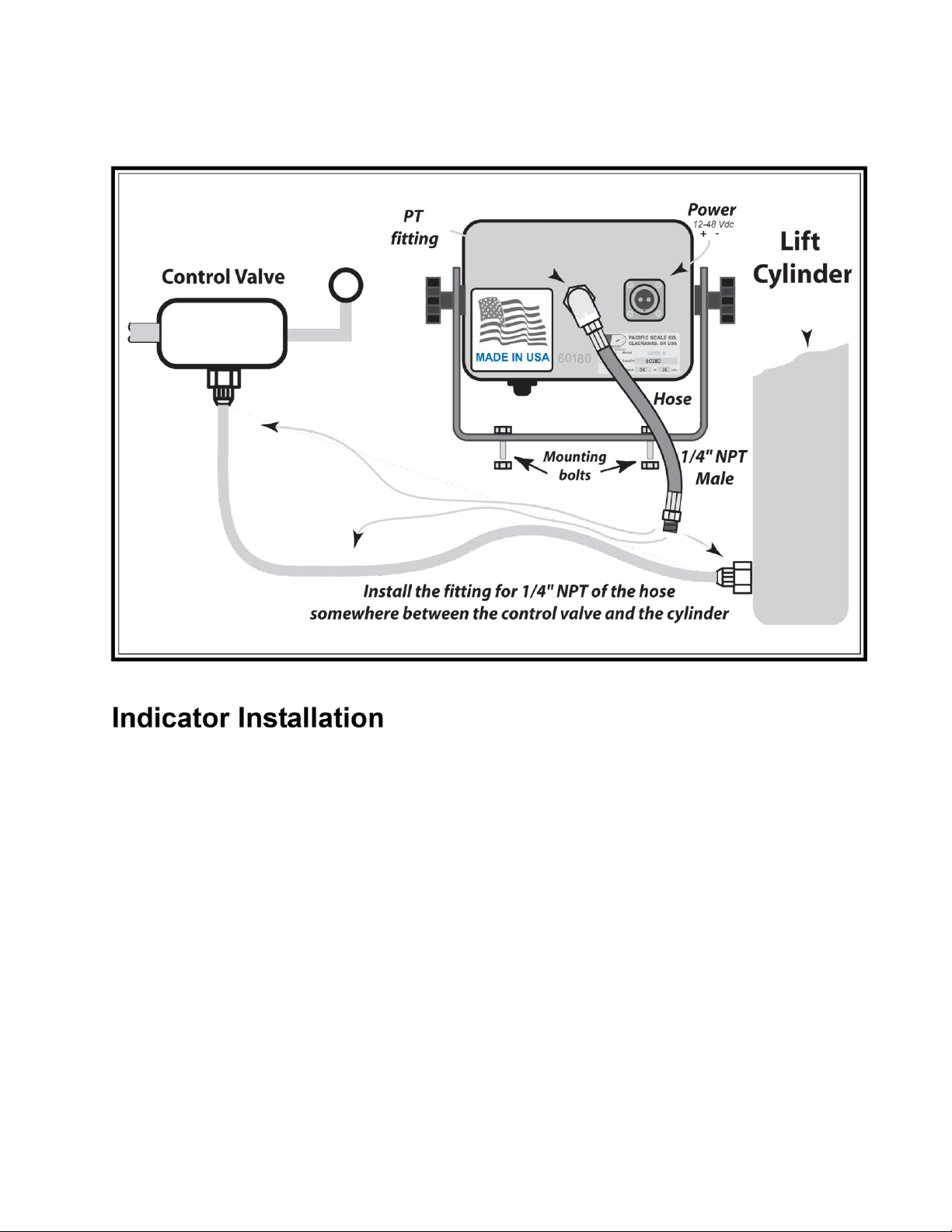
Pressure Transducer
The transducer uses a strain gauge bridge to convert the hydraulic pressure in the lifting
cylinder into a proportional electrical output. This unit is capable of sensing pressure from 0
psi. to 5,000 psi at full scale. The transducer is built into the indicator enclosure for maximum
protection and easier installation. A high pressure hose from the lift truck (see installation
page) connects to a 1/4” NPT female swivel fitting on the back of the indicator housing.
Digital Indication
The LNW indicator uses solid state technology to achieve a high degree of accuracy on the
test bench. This however, is downgraded by the friction and slight differences in psi. during
the lifting cycle in the lift truck. The load on the forks is displayed on a backlighted liquid
crystal display for easy viewing in both bright and poorly lighted situations.
Housing
A heavy cast aluminum housing helps protect the indicator against mechanical damage. All
openings are gasketed and sealed to minimize contamination from dust and moisture.
Power Requirements
The LNW-6 indicator has approx. 100 mA current draw. The LNW Units have the Wide
Input Voltage Regulator (WIVR) installed, as part of the standard unit, and can operate
from 12 to 48 Vdc input and provide regulated power for the Printer and Setpoint options, if
purchased, provided reasonably clean power is supplied.
Due to problems of dirty power, including voltage spikes from gear pump
motors, if the LNW Unit is to be used on DC systems of greater than 24 volts, or used
with options on systems greater than 12 vdc, the installation of a Heavy Duty Line
Filter (HD-LF) and a Heavy Duty Voltage Regulator (HD-VR) may be required.
On 36V or greater systems, use without the HD LF & VR cannot be guaranteed.
Note: If supplied Power falls below 11.5 volts on a regular basis, WIVR may need to be
bypassed. Contact Pacific Scale for information.

LNW-6
Manual Version 5 - effective 15 January 2013 • 2 •pacificscale.com & forkliftscales.us
DC Power Filters
Pacific Scale Co. builds LNW Indicators for use on a wide variety of equipment and vehicles.
Our internal Wide Input Voltage Regulator (WIVR) will work on an input voltage of 12-48
volts DC and has basic power line noise filtering built in.
Depending on design, some vehicles, particularly electric forklifts, may need additional
external power filtering to protect our LNW indicators from surges and power spikes that
may damage our WIVR.
We can pass along suggestions from what our customers have used, but each end user
must determine what their particular equipment requires to provide adequate clean power.
Due to recent electrical design changes on forklifts, Pacific Scale cannot
guarantee that our LNW units will work as is without external power filters
and conditioners supplied by the customer or with filter and regulator we
have provided.
Pacific Scale Co. has included with this LNW unit:
1 SM480-8 Heavy Duty DC Power Line Filter (HD-LF)
1 SM2412-2.5 Heavy Duty Voltage Regulator (HD-VR)
If the customer wishes to use his own filters or if the Heavy Duty external filter and regulator
we have provided are not needed, please return the HD-LF & HD-VR for $25 credit to: Pacific
Scale Co.; LNW Mfg. Dept.; PO Box 1602; 16002 SE 106th; Clackamas, OR 97015
The End User and/or Installer should use their own experience and vehicle dealers
suggestions on the need for additional power filters and conditioners.
One source for vehicle mounted power conditioning equipment is www.servicemate.com
We hope each customer who solves a particular problem can share their experience with
our tech dept. to pass along to new customers via our www.forkliftscales.us website.
For further information contact LNW Tech Support at 1-800-537-1886
Installation
LIFT TRUCK CONDITION - While the LNW indicators are capable of very good accuracy on the
test bench, the lift truck condition is the primary limit on accuracy. To achieve the best

LNW-6
Manual Version 5 - effective 15 January 2013 • 3 •pacificscale.com & forkliftscales.us
accuracy possible, usually approximately +/- 1-2% of the capacity of the truck, the lift truck
should be in good mechanical and hydraulic condition. The lifting mechanism must be
checked for satisfactory operation: leaks; proper fluid level; the mast slides for worn or bent
sections and mast rollers for worn bearings; hoist piston and ram seals for wear; insure
mast slides are clean and lubricated.
INDICATOR INSTALLATION - Mount the indicator bracket to facilitate viewing and necessary
clearances for adjustments (mounting bolts are provided). Connect the power cable to
power sources.
WHITE LEAD SHOULD GO TO THE POSITIVE TERMINAL AND BLACK LEAD SHOULD GO TO THE NEGATIVE
TERMINAL. CONNECTIONS SHOULD BE MADE DIRECTLY TO THE BATTERY TO AVOID ELECTRICAL NOISE.
Note - If the power source is above 24 VDC, the Heavy Duty Line Filter (HD-LF) and
Heavy Duty Voltage Regulator (HD-VR) option may required. Customer can supply
their own voltage converter and/or power filters as long as the LNW Indicator unit
is supplied with clean DC power.
HOSE INSTALLATION - The Standard LNW-6 comes standard with a 6’ hose. Custom lengths
are available. One end of the hose is connected between the lift valve and the primary lift
cylinder(s). The Indicator has the second end of the hose connected to the fitting on the
back. Locate the indicator so the hose and the electrical cable are clear of moving parts
and the display can be seen by the operator.
(See page 4 - Installation diagram )
a. Before loosening hydraulic fittings, insure the release of hydraulic pressure by
lowering the forks to the ground.
b. Somewhere between the lift valve and the lift cylinder(s), install a fitting (supplied by
the customer) that will accept the 1/4” NPT male on the end of the hose. Remember the
indicator must see the pressure in the main cylinder when lifting a load so watch for any
pressure bypasses. If truck has two (2) lift cylinders, be sure you install the hose so
pressure is read from both cylinders. Reading pressure from only one of two cylinders may
be done but may affect accuracy.
c. With the appropriate fitting installed between the lift cylinder and the valve, install
one end of the hose at the fitting and tighten. Attach the other end of the hose to the fitting
on the indicator. Before tightening, pressurize the system and bleed air from the hose. d.
Start the lift truck and check for leaks.
Check Operation (see pages 5 & 6)

LNW-6
Manual Version 5 - effective 15 January 2013 • 4 •pacificscale.com & forkliftscales.us
Indicator Installation
1. Power cord should be plugged in and connected preferably direct to the battery.
2. The LNW-6 has it’s own ON/OFF switch and internal resettable fuse.
Note: Unless customer requests it, do not wire to ignition switch. As the LNW units draw
minimal power, approx. 100 ma, the LNW is unlikely to drain a vehicle battery unless left on for more
than several days. Leaving an LNW On allows for better electronic stability.
3. If the lift truck has twin lift cylinders, be SURE that the hydraulic connection to the
LNW-6 is plumbed into the system so it sees the pressure from the two (2) lift cylinders.
4. If the lift truck has three (3) cylinders, be SURE that the hydraulic connection to
theLNW-6 is plumbed into the cylinder doing the lifting in the first stage. This is usually the
Free lift cylinder.
Operation
Weighing Reference Point
Point established for zeroing and weighing. This point must be within the freelift portion of
the uprights.

LNW-6
Manual Version 5 - effective 15 January 2013 • 5 •pacificscale.com & forkliftscales.us
First Stage Cylinder
The LIFT-N-Weigh will weigh most accurately in the first stage on a truck with telescoping
hoist cylinders.
Weighing Height
Height that provides for consistent weights. (typically 16” to 20” above ground)
To mark weighing height;
a. Raise forks to approximately 16” to 24” above ground level.
(or determine operators choice of height.)
b. Apply one (1) of the supplied red arrow decals to the mast (fixed portion) and
another to the fork carriage (movable portion) directly opposite the first arrow,
within clear view of the operator.
c. Lift a Weight several times and record weight readings. If repeatability is
insufficient for the customer, check again using a different Weighing Height.
Consistent use is the key to good Repeatable weighing
Note: Loaders will have a greater error Range than listed below for Forklifts.
(normally 5% of Capacity depending on equipment and use)
Get Zero
Pick up the empty forks, at a normal lifting speed, to several inches above the mark and
then lower to the mark. Press ZERO
Check for repeating Zero
Repeat procedure several times to assure display repeats within 1% to 2% of the truck
capacity. (e.g.: +/- 50 to 100 Lbs. on a 5,000 Lbs capacity truck) Do NOT keep setting
ZERO if it repeats within that range.
Check for repeating Weight
Pickup a known load (approx. 20% to 50% of the truck capacity) in the same manner and
see if it repeats within the range of 2% of truck capacity.
Then do Calibration if Weight is off
If Display repeats within the 2% range but the weight is wrong, go to the Calibration page
and follow the instructions. (Pages 6, 7, 8)
If Weight does not repeat, try different weighing height
Note: 16” is mentioned as a convenient weighing height. If repeatability is better at another
level, change the reference mark. While Weighing should be done in the first stage, it really
does not matter how it is done as long as you get repeatability at ZERO and with a load - all
within 2% of truck capacity.

LNW-6
Manual Version 5 - effective 15 January 2013 • 6 •pacificscale.com & forkliftscales.us
Working Display and Weighing cycles
The LNW-6 normally displays a “working” weight reading, but for accuracy, the LNW-
6 uses a weighing cycle for a more accurate “calculated” weight.
This eliminates some of the problems of hydraulic weighing systems.
Operation
First step - Turn On Scale
Scale cycles through its power up display. Second
item is Program version.
Second - Zero Scale
1. Lift empty forks at normal lifting speed to above the weighing mark
2. Lower to the weighing mark

LNW-6
Manual Version 5 - effective 15 January 2013 • 7 •pacificscale.com & forkliftscales.us
3. Press to start a weighing cycle.
The Scale cycles through a weigh cycle, getting a Calibrated
ZERO
then showing a working ZERO (displayed value)
(continued on next page)

Zero
Total Weights - ACCUM
Press to get While showing Press to add Press to start a Weighing cycle weight Calibrated Weight
weight to Total and automatically add to Total

OR
Operation (Continued) LNW-6
Third - Get Weight
1. Lift the load at normal lifting speed to above the weighing mark
2. Lower to the weighing mark
3. Press to start a weighing cycle. The Scale cycles
through a weigh cycle,
Getting a Calibrated weight (indicated by * l b )
After approximately 20 secs or the scale is unloaded the
Display returns to the working (non-precision) display.
Accumulation - Totaling Weights
1. Lift the load at normal lifting speed to above the weighing mark
2. Lower to the weighing mark
3. Press to start a weighing cycle. The Scale cycles
through a weigh cycle,
Getting a Calibrated weight (indicated by * l b )
4. While calibrated weight is displayed press to add to the
Total weight.
The display shows the Current Total for approximately 3 secs
Then the Display returns to the Calibrated weight After
approximately 20 secs or the scale is unloaded the Display returns to the working
(non-precision) display.
Single button Accumulation
1. Lift the load at normal lifting speed to above the weighing mark
2. Lower to the weighing mark
3. Press or the Remote button to start a weighing cycle.
The Scale cycles through a weigh cycle,
Getting a Calibrated weight, and displays
The Current Total for approximately 3 secs

Then the Display returns to the Calibrated weight (indicated by * l
b ) After approximately 20 secs or the scale is unloaded the
Display returns to the working (non-precision) display.
Clearing Totals
Remove the load from the forks. While holding the button,
press and hold the until the Count shows Zero, to clear Totals.
Manual Version 5 - effective 15 January 2013 • 7 • pacificscale.com &
forkliftscales.us


Table of contents
Other Pacific Scale Scale manuals