Pacific Scale LIFT-N-WEIGH LNW-4 User manual

LIFT-N-WEIGH
LIFT TRUCK SCALE
Pacific Scale Co. Clackamas, Oregon
LNW-4
ON/OFF SWITCH - ZERO BUTTON
ACCUMULATE-PRINT OPTION
FRONT KEY CALIBRATION
OVERLOAD/SETPOINT WARNING OPTION
RS232 INTERFACE OPTION

Warranty
Pacific Scale Co. warrants to the original purchaser that it will repair
or replace any part which in its judgement is defective in material or
workmanship. Warranty period is 365 days from date of shipment.
Special 5 year warranty on Main board electronics if found to be
defective in material or workmanship. See owner’s manual for
complete warranty and return instructions.
LIFT-N-WEIGH
The Lift-N-Weigh model LNW-4 provides a quick and con-
venient weight check for shipping and receiving. Weigh-
ing while handling eliminates those extra time consuming
trips to a stationary scale. Mounted for viewing, while
not interfering with visibilty, it gives the operator a quick
check for unsafe overloads.
The Lift-N-Weigh operates on the principal that there is a
direct correlation between the pressure in a lift cylinder
and the weight on the forks. A transducer in the instru-
ment changes hydaulic pressure to an electrical signal,
which ends up as a weight reading on the display.
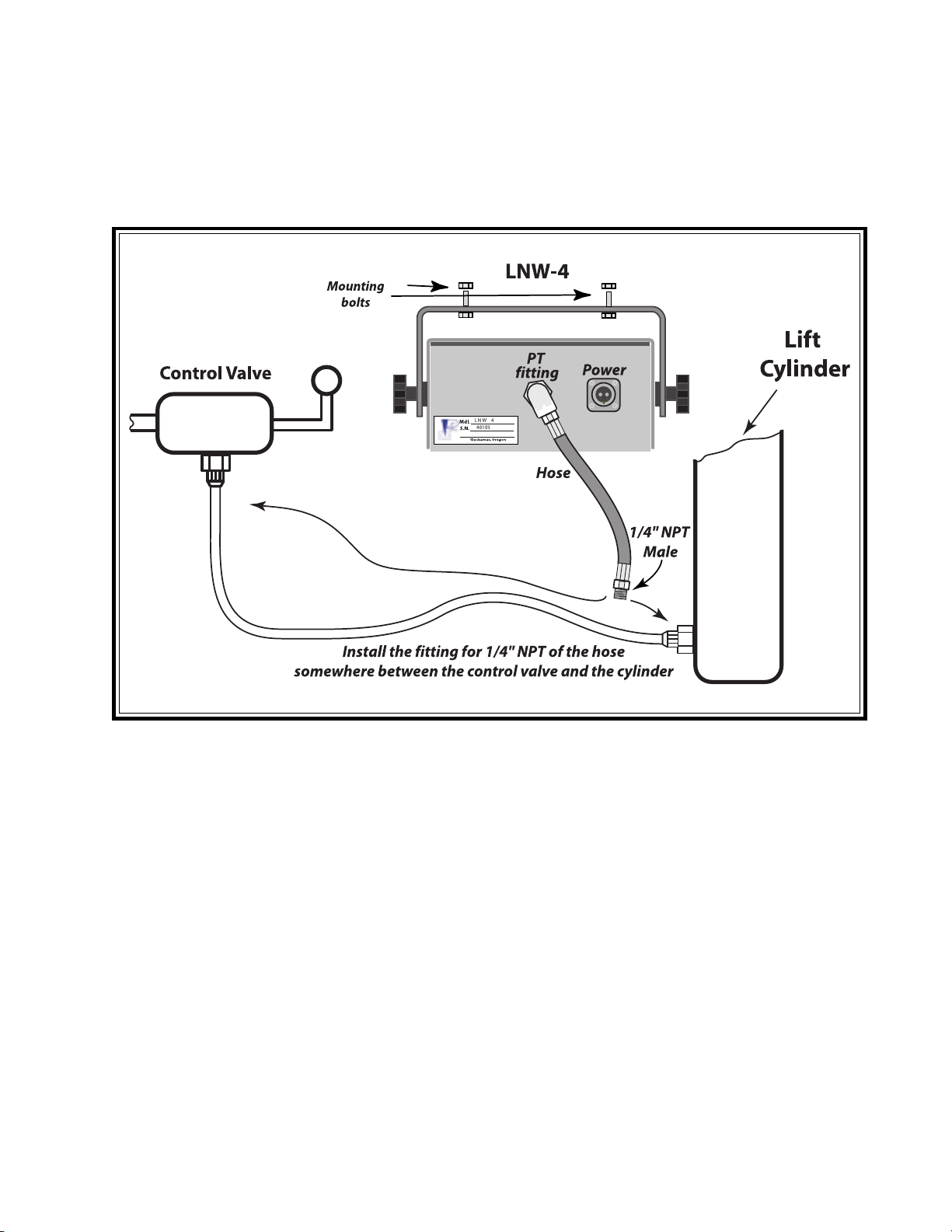
Installation consists of mounting the display at a conve-
nient location. “Teeing” into the lift truck hydraulic line
and connecting it to the display. The D.C. power line is
then connected to the lift truck battery. The unit comes
pre-calibrated for a specific lift truck. If the weight read-
ing is incorrect or the scale is installed on a different
truck it can be re-calibrated in the field. A 6 foot - high
pressure hose and DC wiring harness are included. We do
not furnish the “Tee” fitting to connect to your hydraulic
lines.
SPECIFICATIONS
CAPACITIES - To match the vehicle up to 199,000 lbs.
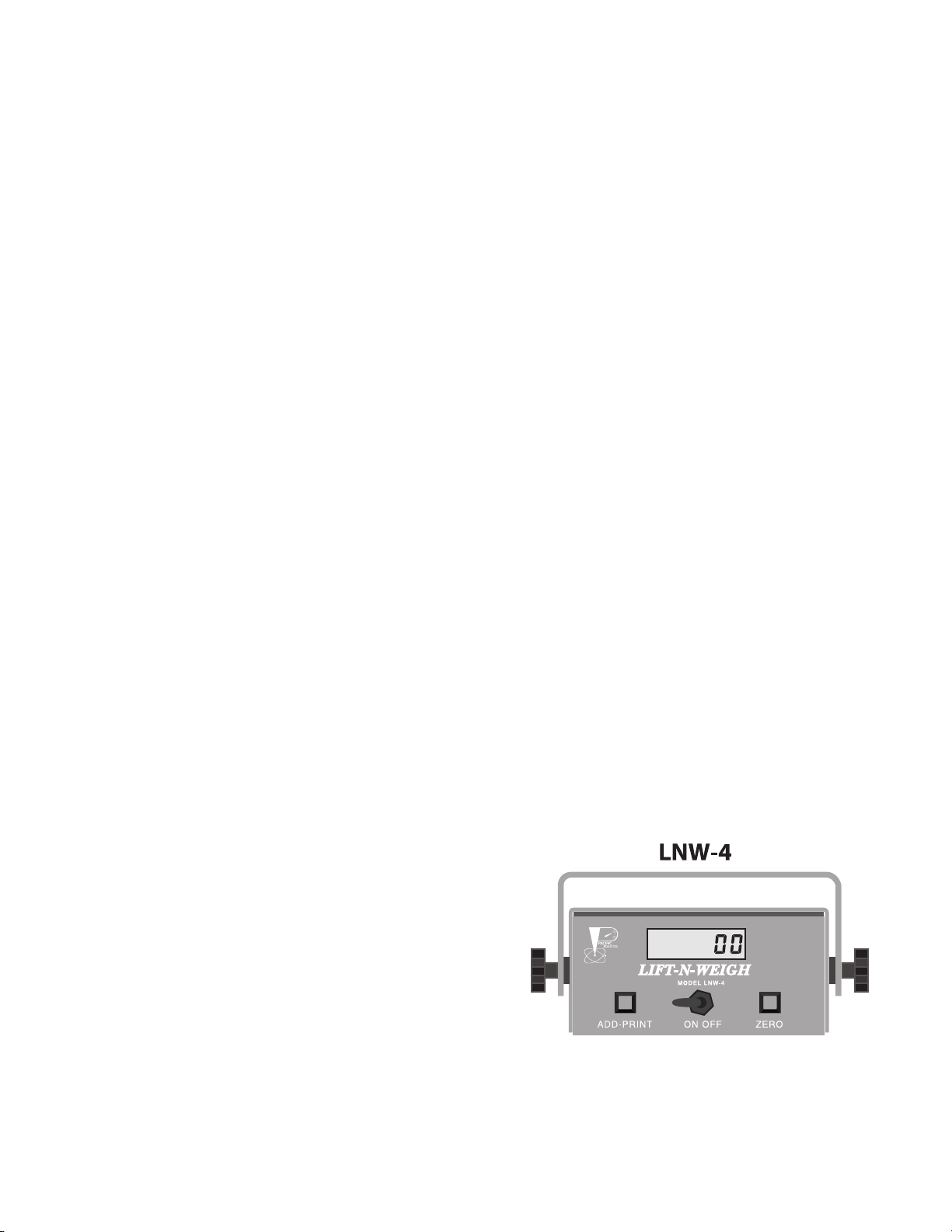
DISPLAY - 6 digit liquid crystal display
height of numbers 0.70”
backlit for high visibility
POWER - 12 volt D.C. to 50 volt D.C. *See Note
CONTROLS - ON/OFF switch
ZERO and ADD/PRINT push buttons
Calibration from front panel using
existing switches.
HOUSING - Cast Aluminum with Powder Coated steel top
GRADUATIONS - 10, 20, 50, 100 lbs.
DIMENSIONS - Housing - 7.5” wide x 6.5” deep
x 3.5” high
Overall - 9.75” wide x 8” deep
x 5.5” high
OPTIONS - RS232 output for Printer or computer
Setpoint to operate overload signal
2-Stage Calibration - for multistage lifts
ACCURACY
The operating accuracy, when installed on the vehicle, is
governed by the mechanical conditions of the vehicle. The
indicator operates off the pressure developed in the main
lifting ram. Because of the friction in the piston and the
mast, actual weighing accuracy will be from 1% to 2% of
the scale capacity for lift trucks. THIS SCALE IS A WEIGHT
ESTIMATOR AND SHOULD NOT BE USED FOR COMMERCE.
P.O. Box 1606 - 16002 SE 106th
Clackamas, OR 97015
Phone (503) 657-7500 - (800) 537-1886
Fax (503) 657-5561
email - psco@pacifier.com
Web - Pacific Scale Co. - www.pacificscal e.com
- LNW Mfg. Dept. - www.forkliftscales.u s
Distributed by:
Note: Electric Systems over 24 Vdc may require DC filters for an additional charge.

LNW-4
LNW 4 Manual Version 6.5 effective 1 Febuary 2007
Table Of Contents
mportant Notice ..................................................................................................... ii
Caution ................................................................................................................. iii
ntroduction & Description ...................................................................................... 1
Principle of Operation
Pressure Transducer
Digital ndication
Power Requirements
DC Power Filters ................................................................................................... 2
nstallation .............................................................................................................. 3
Lift Truck Conditions
ndicator nstallation
Hose nstallation
nstallation Diagram ............................................................................................... 4
Operation ............................................................................................................... 5
Weighing Reference Point
First Stage Cylinder
Weighing Height
Repeatability is the Key to Good Weighing
Description of Controls - ON/OFF, ZERO, ADD/PR NT
Operation (cont.) - Weighing .................................................................................. 6
Set ZERO
To Weigh
Display/Hold
Options; Setpoint, Print
Calibration Procedure ................................................................................ 7& 8 & 9
Check ZERO and Span
Set span
Return to Normal weighing and check Span
Troubleshooting ...................................................................................................10
nstallable Options ................................................................................................ 11
Case Dimensions ................................................................................................12
Serial Output & Printer features ............................................................................ 13
Warranty ..............................................................................................................14
Parts List (partial).................................................................................................15
Main Board Diagram ...........................................................................................16
Wiring connections
Switch settings
Countby (Graduation size - Set to Truck Capacity)
Zero Reset Range
Reset Processor and store Defaults
• i •

LNW-4
LNW 4 Manual Version 6.5 effective 1 Febuary 2007
Important Notice
Your new LNW-4, Serial No.___________, was calibrated for
installation on a Make ________________
Model _____________ before leaving the factory.
Please read the Operating nstructions on pages 4 & 5 and
Troubleshooting on page 9 before attempting to re-calibrate
the indicator.
Do NOT spend over 30 minutes
in testing and adjusting.
If ou spend more time than this or are having problems.
Please call for technical assistance
1-800-537-1886
If ou call, please have available:
1. LNW Indicator Serial number ____________.
2. Make (Truck)____________.
3. Lift capacit of the vehicle____________.
4. Number of Lift c linders______________.
5. D.C. voltage supplied b the truck______.
6. Description of the problem.
• ii •

LNW-4
LNW 4 Manual Version 6.5 effective 1 Febuary 2007
**** CAUT ON ****
Because Lift trucks can vary greatly in their configuration from
Manufacturer to Manufacturer and model to model, the instruc-
tions for installation of the indicator are general in scope. A
qualified lift truck technician may find an alternate means to
install the scale which is better suited to the situation.
Pacific Scale Co., nc. strongly recommends that when instal-
lation procedures are followed which depart from those out-
lined herein, the safety of personnel and equipment must be
accorded primary consideration.
• iii •

LNW-4
LNW 4 Manual Version 6.5 effective 1 Febuary 2007
Introduction
Your new L FT-N-WE GH Model LNW-4 was designed to provide you with a reliable, versatile
and compact weighing system. While there are a number of variables affecting the hydraulic
system pressure - fluid viscosity, temperature, mechanical friction, leaking seals, etc., this
manual is intended to show you how to get the best performance out of your L FT-N-WE GH.
Description
Principle of Operation
The lift truck scale works on the principle that the lift truck hoisting pressure is directly
proportional to the applied weight on the forks. The hydraulic pressure is converted into an
electrical signal by a pressure transducer. After the completion of calibration procedures, the
reading on the display is the weight on the forks.
Pressure Transducer
The transducer uses a strain gage bridge to convert the hydraulic pressure in the lifting
cylinder into a proportional electrical output. This unit is capable of sensing pressure from 0
psi. to 5,000 psi at full scale. The transducer is built into the indicator enclosure for maximum
protection and easier installation. A high pressure hose from the lift truck (see installation
page) connects to a 1/4” NPT female swivel fitting on the back of the indicator housing.
Digital Indication
The LNW indicator uses solid state technology to achieve a high degree of accuracy on the
test bench. This however, is downgraded by the friction and slight differences in psi. during the
lifting cycle in the lift truck. The load on the forks is displayed on a backlighted liquid crystal
display for easy viewing in both bright and poorly lighted situations.
Housing
A heavy cast aluminum housing helps protect the indicator against mechanical damage. All
openings are gasketed and sealed to minimize contamination from dust and moisture.
Power Requirements
The LNW-4 indicator has a Wide nput Voltage Regulatopr (W VR) that allows it to operate on
clean DC power from 12 to 48 Volts DC with approx. 100 mA current draw. Older units, Serial
numbers 40000 to 40120, will operate on 12 to 24 Vdc, as is. f these older LNW-4 Units are
to be used on DC systems of greater than 24 volts, or used with options on systems greater
than 12 vdc, the installation of an W VR is required. The installation of the W VR will allow older
units to operate on DC voltages from 12 to 48 volts and provide regulated power for the Printer
and Setpoint options, (if purchased), provided reasonably clean power is supplied.
LNW-4 units, serial number 40121 and above, have the Wide nput Voltage Regulator ( W VR)
installed, as part of the standard unit, and operate from 12 to 48 Vdc input.
Note: Many newer systems of 36 Volts or above may need an external Heavy Duty Line
Filter (HD-LF and Heavy Duty Voltage Regulator (HD-VR to block power spikes from doing
damage. Contact Pacific Scale for more information.
• 1 •

LNW-4
LNW 4 Manual Version 6.5 effective 1 Febuary 2007
DC Power Filters
Pacific Scale Co. builds LNW ndicators for use on a wide variety of equipment and vehicles.
Our Wide nput Voltage Regulator (W VR) will work on an input voltage of 12-48 volts DC and
has basic power line noise filtering built in.
Depending on design, some vehicles, particularly electric forklifts, may need additional
external power filtering to protect our LNW indicators from surges and power spikes that may
damage our W VR.
We can pass along suggestions from what our customers have used, but each end user must
determine what their particular equipment requires to provide adequate power.
Due to recent electrical design changes on forklifts, Pacific Scale cannot guarantee
that our LNW units will work as is without external power filters and conditioners
supplied by the customer or with filters purchased as an extra option.
The End User and/or nstaller should use their experience and vehicle dealers suggestions on
the need for additional power filters and conditioners.
One source for vehicle mounted power conditioning equipment is www.servicemate.com
We hope each customer who solves a particular problem can share their experience with our
tech dept. to pass along to new customers via our www.forkliftscales.us website.
For further information contact LNW Tech Support at 1-800-537-1886 ext. 109
Or email: [email protected]
Pacific Scale Co. /LNW MFG February 2005
• 2 •

LNW-4
LNW 4 Manual Version 6.5 effective 1 Febuary 2007
Installation
LFT TRUCK COND T ON - While the LNW indicators are capable of very good accuracy on the
test bench, the lift truck condition is the primary limit on accuracy. To achieve the best
accuracy possible, usually approximately +/- 1-2% of the capacity of the truck, the lift truck
should be in good mechanical and hydraulic condition. The lifting mechanism must be
checked for satisfactory operation: leaks; proper fluid level; the mast slides for worn or bent
sections and mast rollers for worn bearings; hoist piston and ram seals for wear; insure mast
slides are clean and lubricated.
ND CATOR NSTALLAT ON - Mount the indicator bracket to facilitate viewing and necessary
clearances for adjustments (mounting bolts are provided). Connect the power cable to power
sources.
WHITE LEAD SHOULD GO TO THE POSITIVE TERMINAL AND BLACK LEAD SHOULD GO TO THE NEGATIVE
TERMINAL. CONNECTIONS SHOULD BE MADE DIRECTLY TO THE BATTERY TO AVOID ELECTRICAL NOISE.
Note If the power source is above 24 VDC, and the serial number is 40120 or before ,
the Wide Input Voltage Regulator (WIVR) option is required. Customer can supply their
own voltage converter and/or power filters as long as the LNW unit is supplied with
clean DC power.
HOSE NSTALLAT ON - The LNW-4 comes standard with a 6’ hose. Custom lengths are available.
One end of the hose is connected between the lift valve and the primary lift cylinder(s). The
ndicator has the second end of the hose connected to the fitting on the back. Locate the
indicator so the hose and the electrical cable are clear of moving parts and the display can be
seen by the operator.
(See page 4 - nstallation diagram )
a. Before loosening hydraulic fittings, insure the release of hydraulic pressure by lowering the
forks to the ground.
b. Somewhere between the lift valve and the lift cylinder(s), install a fitting (supplied by the
customer) that will accept the 1/4” NPT male on the end of the hose. Remember the indicator
must see the pressure in the main cylinder when lifting a load so watch for any pressure
bypasses. f truck has two (2) lift cylinders, be sure you install the hose so pressure is read
from both cylinders.
c. With the appropriate fitting installed between the lift cylinder and the valve, install one end of
the hose at the fitting and tighten. Attach the other end of the hose to the fitting on the
indicator. Before tightening, pressurize the system and bleed air from the hose.
d. Start the lift truck and check for leaks.
Check Operation (see pages 5 & 6)
• 3 •

LNW-4
LNW 4 Manual Version 6.5 effective 1 Febuary 2007
Indicator Installation
1. Power cord should be plugged in and connected preferably direct to the battery.
The LNW-4 has it’s own ON/OFF switch and fuse.
2. f the lift truck has twin lift cylinders, be SURE that the hydraulic connection to the LNW-4 is
plumbed into the system so it sees the pressure from the two (2) lift cylinders.
3. f the lift truck has three (3) cylinders, be SURE that the hydraulic connection to the LNW-4 is
plumbed into the cylinder doing the lifting in the first stage. This is usually the Freelift cylinder.
• 4 •

LNW-4
LNW 4 Manual Version 6.5 effective 1 Febuary 2007
Operation
Weighing Reference Point
Point established for zeroing and weighing. This point must be within the freelift portion of the
uprights.
First Stage C linder
The L FT-N-Weigh will weigh accurately only in the first stage on a truck with telescoping hoist
cylinders.
Weighing Height
Height that provides for consistent weights. (typically 16” to 18” above ground)
To mark weighing height;
a. Raise forks to approximately 16” to 18” above ground level.
b. Apply one (1) of the supplied red arrow decals to the mast (fixed portion) and
another to the fork carriage (movable portion) directly opposite the first arrow, within
clear view of the operator.
Repeatabilit is the ke to good weighing
Pick up the forks about 18” to 20” and then lower about 2”. Press ZERO.
Repeat procedure several times to assure display repeats within 2% of the truck capacity.
(e.g.: +/- 100 Lbs. on a 5,000 Lbs capacity truck) Do NOT keep setting ZERO if it repeats
within the 2% range.
Pickup a load in the same manner and see if it repeats within the range of 2% of truck
capacity.
f Display repeats with the 2% range but the weight is wrong, go to the Calibration page and
follow the instructions. (Pages 6&7&8)
Note: 16” is mentioned as a convenient weighing height. If repeatability is better at another
level, change the reference mark. Weighing must be done in the first stage. It really does
not matter how it is done as long as you get repeatability at ZERO and with a load - all
within 2% of truck capacity.
Description of Controls
ADD/PR NT push-button - Adds displayed weight
into Memory.
ON/OFF Toggle - power switch.
ZERO push-button - Sets Display to ZERO
Note: To ACCUMULATE - the weight shown on
the display must have started within the set ZERO
Reset Range (see Page 16 and then rise above
the Zero Reset range before becoming active.
Note: Program revision PROG92E and above allows the option of a push-button Display
Hold using the ADD/PRINT push-button.
• 5 •

LNW-4
LNW 4 Manual Version 6.5 effective 1 Febuary 2007
Operation (Continued) - Weighing
Zero Set
1. Bring mast to vertical position.
2. Raise forks 2” or so above weighing mark.
3. Jog forks down to mark and press the ZERO button. ZERO NG and WE GH NG must be
done in the same manner and at the same point for consistent weights.
Weighing
4. To weigh a load, lift the load in the same manner as when setting Zero - 2” above the mark
and jog down to the mark. When display pauses or hesitates, read the weight. The pause will
normally be just momentary. Or press the ADD/PR NT button This will ACCUMULATE the
weight or PR NT (if printer option is installed).
Accumulation can onl occur above the Zero Reset Range set in the indicator - See page 13. When the weight
drops to within the Zero Reset Range , the indicator will reset to enable another accumulation and if the indicator is
in the Displa Hold mode, the displa will unlatch.
(Note: when the lift valve is released, the displa will start to drift downward. This is normal, due to bleedback in the
control valves and friction in the s stem. This is wh jogging down the load is usuall required. Watch for a pause
point that is repeatable, for the point to press the ADD/PRINT button).
Clear Total
5. To CLEAR the ADD Total, lower load until display is at or near ZERO. Press and hold ADD/
PR NT button and press and release the ZERO button.
Check Zero during the da
6. Recheck your ZERO occasionally during use. Reset ZERO if it has
changed.
Displa Hold
To enable on Display Hold, first turn unit off. Press and hold the ZERO (Red)
button while turning power on. Display will then flash, showing a “P” and some
numbers. f there are dashes alternating with the “P xxx”, then Display Hold is
Off. Press both of the front panel buttons at the same time to toggle Display
Hold on and off
Options
Printing
An optional RS232 printer output and printer can be
purchased that will print the weight on a roll tape. This
requires the installation of the RS232 option.
Setpoint
Optional Setpoint can be purchased and easily set through the front panel controls. This can
be attached to a Piezo audible alarm or a light to warn the Operator of overloads.
To obtain the above options, the LNW-4 must be returned to the factor for retrofitting unless the
options were purchased at the same time as the LNW-4.
• 6 •

LNW-4
LNW 4 Manual Version 6.5 effective 1 Febuary 2007
Calibration
The Lift-N-Weigh is normally precalibrated to the customer supplied lift truck specifications.
This is a test bench calibration to the calculated pressure. Because of friction in the lifting
mechanism and control valve bleedback, weight errors may exist in the system when installed
on the customers equipment. These can be easily corrected by performing the following
adjustments:
Step 1 - Check Zero. Lift the forks 18” to 24” and lower a couple of inches. Lift at normal
lifting speed. Wait until the numbers on the display pause or hesitate (usually 3-7 seconds) to
take a reading. Do this several times to insure the zero setting is correct
DO NOT BE CONCERNED W TH AN ERROR W TH N 2% OF THE TRUCK CAPAC TY.
(e.g.. tolerance for a 5,000 lb. truck capacity @ 2% = 100 lbs. error plus or minus.)
f the empty (ZERO) weight repeats within 2% proceed to Step 2.
f the empty weight readings DO NOT repeat within 2% tolerance, try lifting the forks to
the weighing height - 16” to 20”- and take your readings as soon as you release the lift valve -
do not lower. Try any method that will give you repeatable readings within the 2% tolerance.
Step 2 - Check Span. Lift a known weight equal to approximately 1/2 of lift truck capacity or
more. Raise the load in the same manner as when setting zero (Step 1). Do this several times
to insure that the system repeats within the 2% tolerance. Repeatability is the key to good
weighments. f correct specifications were given, the indicator is precalibrated before
shipment.
IF THE WEIGHT READINGS DON’T REPEAT WITHIN THE 2% TOLERANCE, TRY A DIFFERENT METHOD OF LIFTING. IF A
DIFFERENT METHOD WORKS, REMOVE THE LOAD AND RECHECK ZERO USING THE SAME METHOD. IT DOESN’T MAKE
ANY DIFFERENCE HOW THE WEIGHMENTS ARE DONE AS LONG AS THE ZERO AND WEIGHT READINGS ARE DONE IN THE
SAME MANNER AND THE WEIGHTS REPEAT WITHIN TOLERANCE.
• 7 •
WEIGHT CAPACITY 2% TOLERANCE
3,000 +/- 60
5,000 +/- 100
8,000 +/- 160
10,000 +/- 200
20,000 +/- 400

LNW-4
LNW 4 Manual Version 6.5 effective 1 Febuary 2007
Calibration (continued)
Step 3 - Set Span.
a. Turn on Display Hold.
To enable on Display Hold, first turn unit
off. Press and hold the ZERO (Red) button while turning power on.
Display will then flash, showing a “P” and some numbers. f there
are dashes alternating with the “P xxx”, then Display Hold is off.
Press both of the front panel buttons at the same time to toggle
Display Hold on and off (see page 6)
b. Turn on Calibration Mode.
To enable Calibration mode, first turn unit off. While holding the ZERO
(red) button AND the ADD/PR NT (green) button, turn on unit.
The display may show “HHHH” until the buttons are released then it
will show a flashing “1” on the left side of the display and the current
weight display on the right. f there is NOT a flashing “1” on the left side
of the display, turn unit off and try step b again.
c. To Adjust weight reading to known load.
First check zero with no weight on scale and then pick up a known weight in the same
manner as normal weighing and press the ADD/PR NT button once to freeze the
reading from the load. Then adjust the displayed weight to match the actual load.
Note: When Display Hold Mode is enabled, you must press the ADD/PRINT (Green
button first, to freeze the scale reading. Otherwise pressing the Zero (Red button first
will Zero the scale.
Pressing the ADD/PR NT (green) button will increase the displayed reading.
Pressing the ZERO (red) button will decrease the displayed reading.
While adjusting displayed weight reading to match actual weight, you can increase the
rate of change while holding the button by pressing and releasing the opposite button.
Example: While in Calibration mode (“1” flashing , you have picked up a 1600 pound pallet and the display
shows “2100”. After pressing the ADD/PRINT (green button once, then holding the ZERO (red will decrease the
displayed reading.
Note: Make sure to do adjustments while using in same manner as already established for repeatability.
To speed up the rate of change while holding the ZERO button, you press and release the ADD/PRINT
button several times to increase the rate of change. As the displayed reading approaches the correct
reading, you release all buttons.
Note: As you approach the desired reading release the buttons and start adjustments again to avoid
overshooting. On early units, overshooting the Span, takes the processor out of range and unit will
lock on Zero. Reset processor to defaults using SW4-1 and SW4-4 (see page 16 and recalibrate.
• 8 •

LNW-4
LNW 4 Manual Version 6.5 effective 1 Febuary 2007
• 9 •
Calibration (continued)
d. Turn Unit OFF then back ON to return to normal weight mode.
Recheck zero, Zeroing if needed. Then pick weight back up to recheck Span.
f display shows correct weight, within 2% of capacity, start using scale.
f displayed weight is out of tolerance, repeat Step 3 - Set The Span
e. f you do NOT wish to use the Display Hold in regular use, turn off now..
To disable Display Hold, first turn unit off. Press and hold the ZERO (Red) button while
turning power on. Display will then flash, showing a “P” and some numbers. f there are
dashes alternating with the “P xxx”, then Display Hold is Off. Press both of the front
panel buttons at the same time to toggle Display Hold on and off (see page 6)
REMEMBER - Repeatabilit & consistenc are the ke to
good weight readings.
Calibration should take less than 30 minutes.
Should you have any problems
call 1 800 537 1886
Also see www.forkliftscales.us for further information

LNW-4
LNW4ManualVersion6.5effective1Febuary2007
Trouble Shooting
Malfunction Probable Cause Corrective Action
Indicator does not
Display numbers Power leads reversed.
Power not connected.
Defective Indicator
Blown WIVR
ConnectWhiteto Positive,
ConnectBlacktoNegative
Connectperinstructions
ReplaceIndicatororplug
ReplaceWIVR,addpower
filterifneeded.
Indicator readings do
not change Transducerconnectedtowrong
sideofvalve
HydraulicHoseobstruction
Loosehydraulicconnection
Reconnect to output of valve
Repair or Replace hose
Tighten couplings
Inconsistentweight Inconsistentweighingprocedure
InconsistentZerosetting
LeakingHoistcylinder
Airin hydraulic system
Mastnot upright
Hoistcylinderfluidlow
Mastslidesdirty
Mechanicalsystemworn/bent
Frictionincylinder,rollers,
slides,etc.
Followrecommendedmethod
Followproperprocedure
Repair
Bleedsystem
Weigh & Zero w/Mast upright
Addproperamountof fluid
Clean&lubricate
Repairasrequired
Lubricatemastparts&be
sureloadon forks is against
thecarriage
Cleanorreplaceplugs;check
wiring&replaceifneeded;
cleannoisycontacts,etc.
Display numbers jump
up & down erratically or
hash is displayed
Electricalinterferencecaused
by:Badignitionsystem,rotating
light,etc.
Tightenscrews&orreplace
gasket
Moisture on inside of
lens Checkcover gasket & screws
IFPROBLEMS STILL EXIST
CALL THE PACIFIC SCALE CO.SERVICE DEPARTMENT
1-800-537-1886
•10 •

LNW-4
LNW 4 Manual Version 6.5 effective 1 Febuary 2007
Installable Options
RS232 Output: ncludes Rear mounted Four (4) pin Receptacle w/screw on Dust
Cover; matching Four (4) pin cable connector, rubber boot, cable clamp; nternal wiring for wiring
RS232 and 11 VDC to the output receptacle. Required for use of a Tape Printer. Can be used to
output to a Computer, used with Barcoding/Terminal equipment, or use with a Remote Display.
Tape Printer: in Separate Enclosure - 6" x 6" x 4" NEMA 4 enclosure; window in
lid; Two (2) quick release clamps to open hinged cover for access to 2.25" wide by 2.75" D
paper tape; dot matrix printer w/cartridge type ribbon. The Printer includes options includes as
standard, Time & Date and Sequential Numbering. The RS232 option listed above is included.
6' Connecting Cable with military style Four (4) pin cable connectors, rubber boots, cable
clamps, for connection to a LNW 4. Additional cable length can be purchased when ordering.
Remote Displa : A 6 Digit Bright LED Remote display. Power and RS232 Data
provided by the LNW-4 Unit via the RS232 Output Option. ncludes 6' of cable
Set Point Control: A single set-point control system with a Three (3) pin
receptacle, rubber boot, cable clamp; nternal wiring for wiring a 10A SPDT relay to the output
receptacle (NO, NC, COM); matching Three (3) pin cable connector, rubber boot, cable clamp.
Dual Calibration: Provides the ability to calibrate the LNW 4 in two (2) separate lift
cylinder stages: e.g. The operator could obtain a weight in the 1st stage (low to the ground)
and in the 3rd stage (high up) - a safety feature to prevent tipping. This option includes a
manual switch on the case to select which stage to display.
Dual Calibration Switch receptacle: The system can automatically
setup a 2-
stage calibration with customer providing a switch fastened to the upright and activated by the
movable section. When the 2nd weighing stage is reached, it would switch the second
calibration
point. Calibration would switch back to first selected stage when the moving portion passes
the
switch on the way down. Switch would have to be a SPST. A receptacle w/10' of cable will be
provided.
Additional Hose length: Charged per foot above the standard 6' hose when
ordering
For further information contact LNW Tech Support at 1-800-537-1886 ext. 109
Or email: [email protected]
Pacific Scale Co. nc. P.O. Box 1606 Clackamas, OR 97015 US
503-657-7500 1-800-537-1886 Fax: 503-657-5561
© Copyright 2005 Pacific Scale Co., nc.. All Rights Reserved.
• 11 •

LNW-4
LNW 4 Manual Version 6.5 effective 1 Febuary 2007
• 12 •

LNW-4
LNW 4 Manual Version 6.5 effective 1 Febuary 2007
• 13 •

LNW-4
LNW 4 Manual Version 6.5 effective 1 Febuary 2007
• 14 •
Warrant
Pacific Scale Co., nc. warrants to the original purchaser that it will repair or
replace - at its option - any part which in its judgement is defective in material
or workmanship. Such repairs or replacements shall be performed without
charge at Pacific Scale’s service facilities.
The defective unit is to be returned to Pacific Scale Co., nc. prepaid with a
description of the problem, after calling and receiving a RETURN MATERIAL
AUTHORIZATION (RMA) number. No unit will be accepted for Warranty without an
RMA number.
This warranty covers:
Entire unit for a period of one (1) year;
Main electronics board for a period of five (5) years;
from the date of shipment from Pacific Scale Co., nc. and is subject to the
following limitations:
Limitations: This warrant shall not appl to -
a. Damage which in the opinion of Pacific Scale Co., nc. is the result of
overloading, misuse, water damage, negligence, alteration, accident or
service performed by other than Pacific Scale Co., nc. authorized personnel.
b. The replacement of expendable or consumable parts.
c. Normal deterioration due to wear or damage and deterioration due to
extended storage or exposure while in the purchaser’s possession before
installation.
This Warranty is the only warranty expressed or implied. Pacific Scale Co., nc.
neither assumes nor authorizes any other person to assume for it any other
obligation or liability. Pacific Scale Co., nc. will not be responsible or liable for
any consequential or contingent damages and its liability is limited to the original
purchase price of the equipment sold.

LNW-4
LNW 4 Manual Version 6.5 effective 1 Febuary 2007
• 15 •
Parts List, (partial)
Description QTY Part NO.
ADD/PR NT Button (Green) .............................................1 L4-AP-PB
Bezel, Silkscreened .......................................................... 1 L4-BZ
Bezel screws ....................................................................4 L4-SZ
Display board, Assy. ......................................................... 1 L4-DB-ASSY
Hose, high pressure synthetic, 6’, 1/4” NPT Male each end......................1 LC-HH-72
Hose Fitting, 360 Deg. swivel ell ......................................1 LC-PT-FS
Main Board ........................................................................ 1 L4-MB
ON/OFF Power Switch, toggle, only.......................................1 L4-PS-ASSY
ON/OFF Power Switch Boot............................................. 1 LC-SW-B
Power Cord Assy..............................................................1 LC-PC-ASSY
nstall Kit ( ncludes Power Cord, Scotchlok taps, Bolts & Nuts, and misc.) ................ 1 L4- nstall Kit
Pressure Transducer ........................................................ 1 LC-PT
Program Chip (Latest Std. version PRO92F - Feb 2003) ............................. 1 L4-PG-F
Top Cover w/Gasket .........................................................1 L4-HT-ASSY
Top Cover Screws ............................................................4 L4-SZ
U-Bracket Mount (w/Knobs) .................................................... 1 L4-UB-ASSY
U-Bracket Knobs, Black ....................................................2 LC-UB-KB
Zero Button (red) ..............................................................1 L4-Z-PB
Table of contents
Other Pacific Scale Scale manuals