Pack Line PXG PL700565 User manual

USER'S MANUAL
F
FI
IL
LL
LI
IN
NG
G
A
AN
ND
D
S
SE
EA
AL
LI
IN
NG
G
A
AU
UT
TO
OM
MA
AT
TI
IC
C
M
MA
AC
CH
HI
IN
NE
E
M
MO
OD
D.
.
P
PX
XG
G
MODEL… PXG
NUMBER…
PL 700565
PRODUCTION DATE…
2013
59, PROFESSOR SHOR STR.- INDUSTRIAL ZONE HOLON 58815 ISRAEL
TEL: 972-3-5581534 FAX: 972-3-5583635
http://www.packline.com E-mail:info@packline.com

CONTENTS
1 Delivery set 2
2 The machine purpose and production versions of the
machine
2
3 Technical data 2
4 The machine preparation for the performance 3
5 Description of the construction and performance
principle
4
6 Adjustment of the machine 11
7 The machine operation order 13
8 Troubleshoots 14
9 The machine maintenance 15
10 Safety rules 16
11 Warranty 16
Recommended spare parts 17
ANNEXES

2
1
D
ELIVERY SET
1 PXG machine as an assemble 1 PC
S
2 The frame legs support 10 PCs.
3 Air feeding tube 1 PCs.
4 Tools and spare parts box 1 PCs.
5 Outlet conveyer 1 PCs.
6 Manual 1 PCs.
7 Product feeding hopper 1 PCs.
2
T
HE MACHINE PURPOSE AND PRODUCTION VERSIONS OF THE MACHINE
Filling and sealing automatic Machine model PXG, further “machine” is intended
for dosed filling and hermetic sealing of products in plastic containers. The
machine tightly seals containers with the membrane cut from a roll.
The customer’s specification includes the product description and containers
sizes. The machine is provided with the appropriated filling assembly.
3
T
ECHNICAL DATA
№Parameter Value
3.1 Nominal air pressure, bar 6-8
3.2 Consumed power, watt 2500
3.3 Power supply line voltage, volt ~3x(200-230) V
3.4 Control panel voltage 24 DC
3.5 Dimensions, mm
- length
- width
- height
3100
1000
2160
3.6 Weight, kg ~1800

3
4
T
HE MACHINE PREPARATION FOR THE PERFORMANCE
The machine mounting and its initial adjustment is carried out by the
manufacturer’s representative or by a trained specialist.
Initial adjustment and starting without the assistance of appropriate
specialist is forbidden !!!
The following operations have to be performed prior to the machine starting:
4.1 Unpack the machine.
4.2 Take the machine frame legs out of the box. Screw the legs into the
special holding holes placed at the frame corners. Adjust the machine level by
means of the legs rotating (pic.1). When the machine will reach the horizontal
position, screw the contra-bolts. Therefore the machine legs will be fastened
relatively to the frame.
4.3 Release the machine from the packing materials and cut off all the plastic
straps, holding the movable parts of the machine during the transportation.
4.4 Inspect the machine and make sure that all the mobile parts are released
and there are no strange subjects at the machine.
4.5 Connect the hopper, outlet conveyer and outlet table to the machine in
accordance with the appropriate’ marking.
4.6 Inspect the machine and make sure that all the wires are connected and
that they have not been damaged during the transportation. Make sure that
there is the suitable electric voltage in the electric socket, prior to switch on
the machine (see technical data). Make sure that there is the earth in the
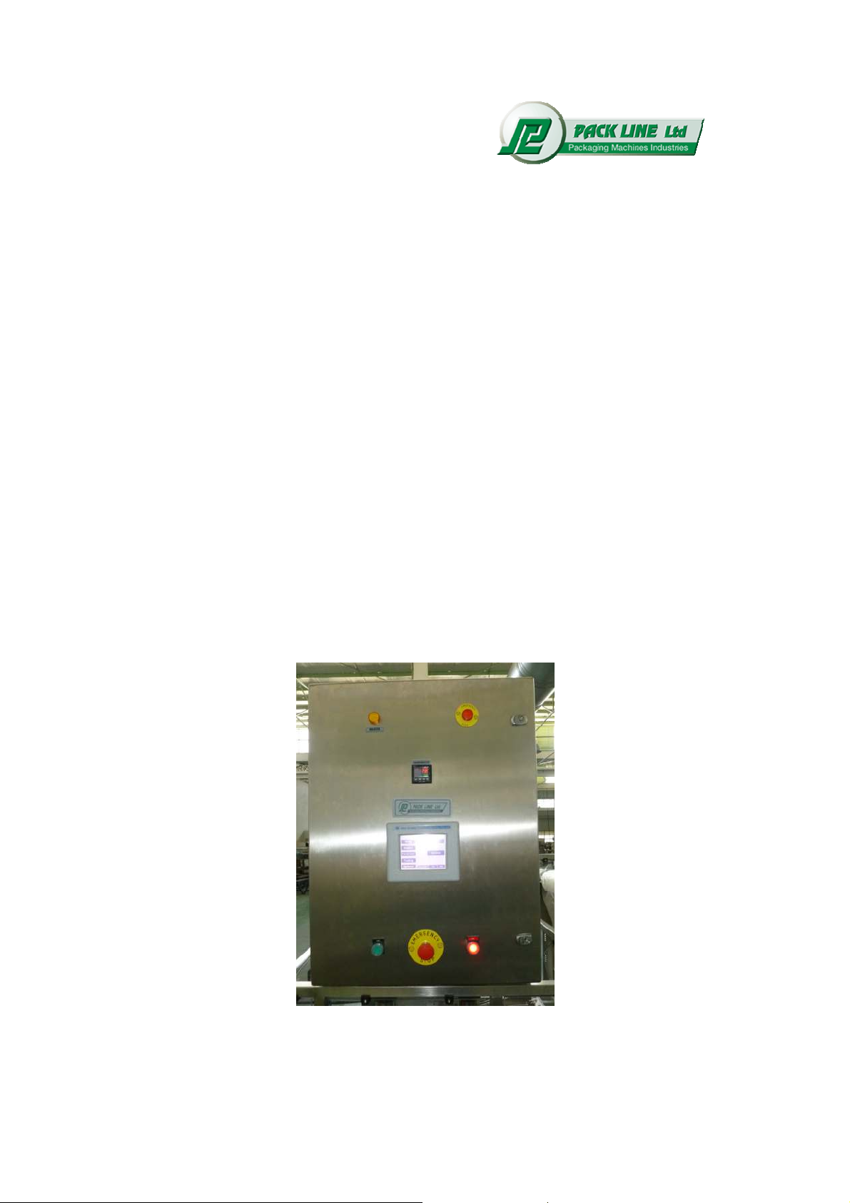
electric socket. Insert the machine’s plug into the socket. Switch on the
general switcher. At that the indicating lamp will light up at the power supply
unit (inside the cabinet), and the computerized controller screen will be
switched on as well. If the above mentioned has not been performed, it's
necessary to switch off the machine and to invite a technician.
4.7 Check the pneumatic system tubes integrity. Inspect the machine and
make sure, that all pneumatic tubes are connected and that they have not
been damaged during transportation and adjustment. It is necessary to feed
the pressed air to the machine and to switch on electric supply (see p. 4.6) at
that all the machine’s assemblies will get in their initial position. Inspect the
machine once more and check the tubes and connections make sure that
there is no air leakage. If you find the air loss, disconnect the pressed air
from the machine and eliminate the fault reason.
4.8 Perform the machine connection to the plant earth system by means of
the earth bolt placed under the electric cabinet on the frame.

4
5.
D
ESCRIPTION OF THE CONSTRUCTION AND OF THE PERFORMANCE PRINCIPLES
5.1 Description of the construction.
The machine (pic. 1) consists of the welded frame on which the following
assemblies are mounted:
Cassettes shifting assembly
Vertical shifting lifts
Cassettes for containers travel
Containers feeding assembly
Fillers
Containers’ sealing assembly – (PAO)
Perforation assembly
Final product ejection assembly
Final product outlet conveyer
Electric cabinet
Regulated legs
All mechanisms are activated by pneumatic cylinders. Film rewinding assembly,
and final product outlet conveyer are activated by electric motors. The machine
operation is carried out by means of the programmed controller.
The machine’s frame is provided with easy removable panels with magnetic
interlocks and safety guarding.
5.2 The operating elements placement at the electric cabinet panel (see pic.)
Electric cabinet consists of following elements:

5
Metallic carcass of the cabinet
Computer’s screen
General power supply switcher "Power"
Emergency stop button “Emergency Stop” – press the button to null
the pressure and to switch off electric supply
Button “Start”
Button “Stop”
Lamp “Emergency” gives the signal, that the “Emergency Stop” button
is pressed or that the machine emergency stop is occurred.
Lamp “Alarm” gives the sealing assembly heaters fault signal
Thermostats of the containers sealing assembly
5.3 Programmed controller’s description
The machine provided with the programmed controller PLC.
Computer’s screens and their operation order:
5.3.1. “Main screens”
The main screens appear on the controller’s display after the machine switch on.
The menu intended for changeover to the auxiliary screens is performed on this
screen.
Work – work screen
Station – the machine single assemblies switch on/off
Parameter – parameters setting and changing screens
Tuning – setting screens
Options – the maintenance screens
Heater – heater - switch on/off
Rewind – film rewind on the PAO assembly switch on/off
To changeover to required screen, choose an appropriate screen by means of
arrows.
The main screens appear on the controller’s display after the machine switch on.

6
5.3.2. “Work” screens
Following elements are performed on this screen:
Pump – the pump on the filling assembly
Home – start the outlet conveyer “zero” positioning mode
The menu intended for changeover to the auxiliary screens is performed on this
screen.
5.3.3 “State” screens
These screens are intended for the machine’s single assemblies’ switch on/off.
In order to switch on/off machine’s single assemblies it is necessary to press
appropriate buttons on the controller’s panel. At that condition symbol “Off” or
“On” on the screen will change.
“Cups” – cups feeding assembly
“Filling” – filling
“Fill Lift – the lift of the filling assembly
“Sealing” – containers sealing – PAO assembly
“Gas” – gas feeding on the PAO assembly
“Band” – film rewind after signal of photo eye on the PAO assembly
“Sealing 2 ” – containers sealing 2
“Puncher 1-2 ” – containers punching 1-2
“Puncher 3 ” – containers punching 3

7
5.3.4 Parameters Screens
These screens are intended to change the machine single assembly's
parameters.
In order to change the value enter the new one and press the “<┘”
Once the “<┘” button was not pressed the value will not be changed
Press the “<-“to cancel the "ENTER”
PARAMETER’S LIST AND THEIR DESCRIPTION:

8
Attention!!!
Parameters value stipulated in the table are approximated and need additional
correction during adjustment
Parameter name
Default
value,
sec
Actual
value
sec
Parameter description
Cups Holder Open Time
00.20 Time required for the chokes opening
on the containers feeding device
Cups Holder Close Time
00.20
Time required for the chokes closing
on the containers feeding device
Cups Vacuum Off Delay
00.20
Time required for the vacuum
presence on the vacuum pad under
containers feeding assembly
Cranes Close Time
00.20
Time required for the choke closing
on the filling assembly
Valves Open Time 00.20
Time required for the valve
opening on the filling assembly
Valves Close Time 00.20
Time required for the valve
closing on the filling assembly
Cranes Open Time
00.20
Time required for the choke opening
on the filling assembly
Fill Lift Down Delay
00.20
Time delay required for the lift getting
down on the filling assembly
Gas Time 00.80 Time required for the gas feeding on
the PAO
Vacuum Time 00.80 Time required for the gas feeding on
the PAO
Sealer 2 Down Delay 00.40 Time delay to second pneumatic
cylinder performance on PAO
Sealing Time
00.80
Time required for the PAO assembly
performance
Rewind Time 00.60 Time required for the film total rewind
Reverse Time 01.20 Time required for the film rewind
backwards
After Band Delay 00.20 Time delay for the film rewind after
signal from photo eye
Puncher -1 Time 00.60 Time required for the puncher 1
performance
Puncher -2 Delay 00.20 Time delay to puncher 2 start
Puncher -2 Time 00.60 Time required for the puncher 2
performance
Puncher -3 Time 00.60 Time required for the puncher 3
performance
Pump On Delay 01.20
Time delay required to start up the

9
pump performance
Pump Off Delay
01.20
Time delay required to accomplish the
pump performance
5.3.5 Tuning screens
This screen is intended to inspect the machine single assembly's performance
order and as well to regulate containers feeding assembly
After switch on the “Test All”,containers step by step movement will start and all
previously switched on assemblies will perform their operation (see p. 5.3.)
After switch on the “Lifts Up”, cassettes will move to one position, and lifts
(see picture 1) will go up and will be fixed in upper position. It is necessary for
adjustment of the containers feeding assembly.
After switch on the “Filling-1-2” the filler-1-2 will perform its operation
After switch on the “Filling-3-4” the filler-3-4 will perform its operation
After switch on the “Sealing” foil sealing and cutting assembly will perform its
operation
After switch on the “Puncher 1-2” punching 1-2 assembly will perform its
operation
After switch on the “Puncher 3” punching 3 assembly will perform its operation
In order to switch off the above modes and to take the machine back into its
initial position press the buttons on the control panel in accordance with the or
press the “Stop“ button on the electric cabinet panel.

10
5.3.6 Maintenance screens
“Washing 1 ” – switches on washing mode of the filler - 1. It is necessary for
product leftovers producing at the end of the working shift and for the machine
maintenance. Press the button repeatedly to get out of this mode.
“Washing 2 ” – switches on washing mode of the filler - 2. It is necessary for
product leftovers producing at the end of the working shift and for the machine
maintenance. Press the button repeatedly to get out of this mode.
“Dose 1 “ “Dose 2 “
This screen is intended to adjust the fillers pistons in upper position and allows
the dose regulation.
5.3.7. “Faults”
If there are any faults in the machine operation process, the fault report will
appear on the current screen including the fault code.
At the same time the machine will be stopped and the “Stop” button will blink. To
continue the machine performance it is necessary to eliminate the fault reason,
and then to press the “Stop” button.
When the fault will be eliminated the machine can be started by the “Start”
button”
Alarm
CUPS MISSING
Press
Stop to Clear
5.4 The machine initial position
The machine is mounted and connected to all systems as per p. 4
Electric supply is switched on and the pressed air is fed.
Containers are set in appropriated magazines.
Cassettes are stopped
Containers’ ejection assembly is in initial position.
5.5. Operating principle of the plastic containers carrying cassettes step-type

11
shifting. (pic 4)
Initial position of cassettes and mechanisms see at pic. 4-1
Pneumatic cylinders 1 and 2 move upper and lower level cassettes up
to the catches 3 and 4, which corresponds to their change for one step
(pic 4-2)
During the moving grabs 5, 6 and 7, 8 (pic 4-2) are drawn out and hold
cassettes at the upper level.
When cylinders 1 and 2 rods get back to initial position (rods drawn in)
lifts 9 and 10 go up, at that lift 9 takes up the cassette from the lawyer
level, and lift 10 surface becomes the upper level cassette support (pic
4-3).
Prior to lifts lifting grabs 7 and 8 draw into their sockets, and lift 9 easily
lifts cassettes to the upper level.
When lifts reach the upper position grabs 7 and 8 draw out to support
the lifted cassette at the upper level, and grabs 5 and 6 draw back into
their sockets, making the passage for the cassette to the lower level by
means of the lift 10 (pic 4-4)
Lifts 9 and 10 get to their initial position after moving cassettes by
vertical.
The system got back to its initial position and it is ready for the next
cycle. (pic 4-5)
Thus we get a system, which consists of cassettes, shifting step-type by guides
at two levels up to catches in closed cycle. Mechanisms’ step-by-step movement
and their positions see on the picture 4.
6.
T
HE MACHINE ADJUSTMENT
The machine’s single assemblies switch on/off, test mode start up, and all timers
setting are carried out on the controller’s screen (see p.5.3)
Prior to the machine start up it is necessary to check its mounting integrity.
Perform following operation:
6.1 Check the set air pressure at the machine inlet.
The compressor manometer’s pressure must be 8 bar, the air preparation blocks
manometers pressure must be 6 bar. If required regulate by appropriate pressure
regulators, at that the compressor must be switched on at 7 bar and switched off-
at 9 bar.
6.2 The main switcher “Power” (pic.2) set in position “1”
Release the button 4 “EMERGENCY STOP”
6.3. Switch on heaters switcher “Heater” in the “On” position .Then set the
temperature at the thermostats (pos.9 pic.2) in the interval of 200 – 280 C
(determine by an experience)
6.4 After switch on the power supply the “Main Screen” will appear on the
controller’s display (see p. 5.3)
Changeover to the screen “Tuning” (see p. 5.3), and switch on the machine in
test mode. Thus you will check the cassettes shifting mechanisms integrity. Then

12
switch on all assemblies and make sure in their complete performance integrity
relatively to each other.
6.5 Repeat the operation 6.4 few times and make sure that all assemblies
operate smoothly without any strikes in closed cycle.
6.6 Start the machine in the “Start” mode.
6.7 Let the machine perform in this mode for few minutes, make sure in its
performance order and stop it by means of the “Stop” button.
6.8 If required perform following regulations:
6.8.1. Containers feeding assembly adjustment (see pic.5)
Fill the plastic containers assembly (pic 1) with containers up to guide's level,
start the machine and check an accuracy of containers one by one feeding into
cassettes.
If required perform following regulations:
Changeover to the “Tuning” screen (see p. 5.3) and press the button “Lift up”.
When lifts will be fixed in upper position, regulate a height of the plate 1 such a
way to put the containers bottom onto the lift 5 surface as per the picture. The
regulation must be carried out by means of the plate 1 shift along supports 2 by
turning handle 3 and further fixation by handle 4.
The regulation is considered as accomplished when containers can be separated
one by one from the common pile.
6.8.2 Adjustment of the membrane sealing and cutting assembly.
The cylinder rod’s shifting rate is regulated by throttles (up) and (down). The
cylinder must operate smoothly without any strikes. When the cylinder is in the
upper position, magnetic indicators’ contacts, which are placed on cylinders,
must be closed. Indicators’ placement regulation is carried out by means of
indicators shifting along cylinders’ axle. Switch on heaters on the controllers’
screen (see p.5.3) let them 20 minutes for heating, set a temperature in the
interval of 200 – 280 C by thermostats 9 ( pic 2). Set the sealing timer on the
controller’s screen for the “Sealing Time” in the interval of 0.8 – 1.5 sec. (see p.
5.3)
The adjustment can be considered as accomplished in following cases:
- cylinder operates smoothly without any strikes;
- when the cylinder’s piston is in upper position, magnetic indicator’s
contacts close and a membrane is sealed tightly to a container along all
perimeters.
Elements of the film wind and rewind assemblies of the PAO assembly
pic. 8
Press roller
Photoelectric eye for the film mark detection
Blocks of sealers and knifes
Bolt intended for fixing the plate with sealers on the axle
Key for the bolt (missing on the picture)
A catch intended to fix plates with sealers blocks in upper position
Film waste rewinding axle
Tape brake

13
A cassette with containers placed exactly under sealers.
Set the film in accordance with following order pic 8:
- take off the tape brake, take off the axle, take off the mobile cone, arrange
a film roll on the axle and fix it by mobile cone. The stable cone has to be
arranged once and must not be rearranged.
- Mount the axle with the roll on the supports. Mount the tape brake
- Release the bolt by the key
- Lift plates with sealers blocks and fix them by the catch
- Draw the film as per the diagram
- Take down plates with sealers blocks and fix them with the bolt by the
key Take down the roller
- Thus the film drawing process is accomplished.
-
6.8.3 Filling assembly’s adjustment (see pic.3;)
Filler’s performance principle (pic 3)
Pneumatic cylinder 8 draws pistons 6 downwards, at that pneumatic cylinder 4
closes outlet hole of filling head 5, and cylinder 3 turns turning valve 2 and
connects cavities of the filler’s cylinders with the product hopper 1.
Product’s sucking is performed. A dose value is adjusted by the shift of the end
of the rod 13 till the catch 10, regulated by the handle 12 and fixed by the handle
11. The sucking rate is regulated by means of the throttle.
The rate of the sucking process must be regulated such a way when the rod’s
end reaches the catch 10 in the machine’s automatic mode (open the throttle 15
turning the handle anti – clockwise).
After getting the command for filling pneumatic cylinder 4 opens the valve 5, the
piston 6 goes upwards, at that turning valve closes and cuts the product inlet
hole.
The set dose fills the container. Filling rate is regulated by means of the throttle.
Filler’s regulation.
Switch on a dose regulation mode (see p. 5.3) When the filler’s rod will be fixed
in drawn in position, it's necessary to release support handle 11 (see pic.3) and
to place the catch 10 at the required height (turn the handle 12). Fix the reached
position by the handle 11. Then press the “Dose” button on the controller’s
screen, at that the end of the rod 13 will reach the catch 10.
Check the issued dose. If required repeat above described operations to reach
required results.
7
T
HE MACHINE OPERATING ORDER
.
7.1 Machine start in operating mode is carried out after executing of all
procedures as per p.4 and p.6
7.2 Make sure that all assemblies are switched at the controller’s screen (see
p.5.3)

14
7. 3 Start machine by pressing “Start” button
7.4 During the machine operation it is necessary to inspect containers and foil
presence. Feed the appropriate magazines, if required. At containers’ lack the
machine will count ten empty cassettes and will stop. If there is no containers,
none assembly will perform operation.
7.5 In order to stop the machine press the “Stop” button. Machine will accomplish
the operation cycle and will stop.
7.6 Press the “Emergency Stop” button for the machine emergency stop. At that
electric supply will be switched off immediately and air pressure will be broken.
8
T
ROUBLESHOOTING
No Malfunction Reason
What to do
8.1
Containers are not fed
from the magazine
Containers are not
separated from the pile
Pneumatic cylinder of the
magazine is fault
Gap between the lower
container’s bottom and
the lift surface in upper
position is set insufficient
Check the containers’
separation from the pile
Avoid the moisture getting
to the pile
Check Pneumatic
Cylinders
Carry out regulations as
per p 6.8. (pic.5)
8.2
Insufficient sealing of
the membrane cut from
the roll to container
The heater is not hot
enough
Membrane’s bubbling
caused by steam
because of the high
heating temperature and
of the seal fault
Insufficient duration of
heating contact
Product is burnt at the
heater
Choose the suitable
temperature depended on
the foil and containers
material
Set the suitable heating
temperature at the
thermostat
Choose the suitable
contact duration
Clean the heater
8.3 Cassettes do not shift
There is no pressed air in
system
Cassette stocked at the
upper level during going
down
Make sure that the
pressure at the manometer
is 6 bar
Press “Emergency” stop
and put the cassette at its
place

15
8.4 Insufficient
performance of the
filler
The filler doesn’t issue a
dose
The filler’s regulation is
fault
There is a drop on the
filler’s nozzle (defected
net in the filler’s end)
The level indicator doesn’t
perform its operation;
product sucking pump is
not switched on.
Regulate the indicator’s
sensitivity (regulation
screw is on front part of the
indicator)
Regulate the filler as per
p.6.8
Change the seal of the
filling head valve
8.5 The fault report
appears on the screen
The fault reason appears
on the controller’s screen
Eliminate the fault reason
9
T
HE
M
ACHINE MAINTENANCE
9.1 Prior to the machine daily starting it is necessary to perform the following
operations:
- Place cups into appropriated magazine
- Start the machine as per p. 7
Perform the adjustment operation as per p.6 if there is found any faults in its
function
9.2 After the machine function completion it is necessary to perform the following
operations:
- Remove the product leftovers from the cassettes if there are any.
- Check the heater’s surface and clean it if needed
- Remove cups leftovers from the magazine
- Clean the filler’s details from the product leftovers
- Process all product form the product hopper.
- Fill the hopper with the hot water,
- Switch on the machine in the cleaning rate. Switch on the “WASH” mode
on the computers maintenance screen. as per p. 5.3.
- In this mode the filler starts to function nonstop. The rest assemblies do not
function. Look for the clean water running from the nozzle
- Process all water in the hopper
- Disconnect electric supply and air
- Remove all the straps from the filler and disassemble it
- Put all parts into vessel with 1% caustic sodium (NaOH) solution at 65°
for 20 minutes
- Wash all parts of the filler in hot soap solution
- Wash all parts in clean water and dry them
- Blow all assemblies of the machine with pressed air.

16
- Assemble the machine in contra order
9.3 Bearings lubrication
Bearings are normally packed with a high quality bearing grease. However,
bearings will require periodic greasing. Bearings should be greased with NLGI #3
bearings grease or similar at least once per month.
Lubrication points see pic.
9.4 Maintenance plan
Daily:
Cleaning
Monthly:
Lubricate lubrication points on the operating side with a
small amount of ball bearing grease.
Clean, check and if necessary replace the seals.
Half-yearly:
Check entire electrical system including connection cable.
Annually:
Check all bearings.
Replace drive belts when wear is noticeable.
Clean, check and if necessary replace the seals.
Finally test run.
Biannually:
Replace drive belts.
10.
S
AFETY RULES
10.1 The machine may be operated only by trained personnel, who are familiar
with the registration certificate and safety rules.
10.2 Running the machine with damaged earth is prohibited
10.3 The machine repair is forbidden unless power supply and compressed air
are disconnected.
10.4 Repairs and adjustments must be performed by high skilled personal
10.5 Be careful during the repairing to avoid your hands’ traumas
10.6 Cooling the heater with water is prohibited. If necessary, cool it with
compressed air.
10.7 Its forbidden to open the machine’s safety guarding during the machine
performance. If it still has happened the machine will stop immediately.
11.
W
ARRANTY
11.1 The warranty period amounts to 12 months starting the day of its
commissioning, however, it cannot exceed 15 months from the date of shipping,
and that is only if the machine is handled by this instruction manual.
11.2 The warranty covers all parts and equipment damaged due to
manufacturer's fault,
11.3 A warranty period having been over, the supplying company undertakes to
provide services to the machine according to prices set out in the contract of
insurance to be concluded annually.
11.4 Repairs or substituting parts within the warranty period does not mean any
extend of the warranty period.
11.5 The warranty is voided unless any changes in electric, mechanical or

17
pneumatic parts were carried out under agreement with the supplier, or if the
machine was transferred to a third part.
11.6 The warranty does not cover mechanical rubber goods with high wearing
capacity and the heating elements.
11.7 The manufacturer is entitled to alter the machine design even if such
alterations are not specified in this certificate, provided they do not deteriorate
technical characteristics, but eased adjustment of the machine
RECOMMENDED SET OF SPARE PARTS FOR THE MACHINE PXG
SERIAL NUMBER PL700565
POS. TITLE MARKING
(SIZE)
UNIT QTY
1 Heating element 6"x1/2" Straight Sealing -PAO 4
2 Ring thermocouple TK - M6 Sealing 1
3 Set springs:
-short
-long
M-441
M-1131
Sealing -PAO
4
4
4 O-Ring 10x16x3 Sealing -PAO 8
5 Sealing ring C063192V 4
6 Sealing ring EGMO-2in-838124-Ring Filler 4
7 O-Ring 16x8x4 Lift 8
8 O-Ring 23,4x3,53(N213) Fillers head 4
9 O-Ring 34.52x3.53(N220) Filler 4
10 O-Ring 30x5(11BY31) Sealing -PAO 2
11 O-Ring Record 1” Sealing -PAO 6
12 Dichtring 3A-1” Filler 4
13 Dichtring
3A-2” Filler 8
14 Dichtring
3A-6” Filler 1
15 Dichtring
3A-4” PAO 1
16 Silicon vacuum pad Piab-F30-1_8-PA Cups feeding 4
17
Timing Belt B=15mm 390-3MR Sealing -PAO 2
18
Membrane Membrane-T-1797 Filler 4

700565
Pic.1
OUTLET
CONVEYER
EJECTION
ASSEMBLY
LIFT
FILLERS LIFT
LIFT
WELDED
FRAME
REGULATED
LEGS
CASSETTES SHIFTING
ASSEMBLY
CUPS FEEDING
ASSEMBLY
PHOTO EYE
FILLER
ELECTRIC
CABINET
FOIL SEALING AND
CUTTING ASSEMBLY - PAO

700539
Pic.3
Table of contents