manuals.online logo
Brands
  1. Home
  2. •
  3. Brands
  4. •
  5. Rodix
  6. •
  7. Industrial Equipment
  8. •
  9. Rodix FC-42-DC Plus User manual

Rodix FC-42-DC Plus User manual

Model - FC-42-DC
Plus
P/N 121-000-0770
Circuit Board P/N 24-210
Input: 120 VAC, 50/60 HZ.
(Operating range 90-130 VAC)
Dual Unit Fuse Size:
Unit A: 10 AMPS, Unit B 5 AMPS
Outputs: 0-90/130 VDC
80% Duty Cycle at Rated AMPS
© 2000, 2011 RODIX INC.
1. SELECT THE PULSE SETTING
Set DIP switch (S1) to 120 on the circuit card.
Note: Readjust the MAX trimpot after changing
pulse switch setting.
2. FUSE SIZE
To avoid failure of the DC motor, the fuses on this
control must be resized to match the fuse size listed
on the motor nameplate. Do not exceed 10 Amps
maximum on Unit A and 5 Amps maximum on Unit B.
3. LIMITING THE MAXIMUM
OUTPUT OF CONTROL
The MAX output trimpot can be adjusted to limit the
maximum vibration level of the vibratory feeder when
the Main Control Dial is fully turned up. When setting
up the MAX output of the feeder control, the output
wiring to feeder must be connected and the control
set for the proper pulse (60 or 120) setting. The Run
Jumper must be connected as shown on the wiring
diagram or on the ON/OFF Control Guide.
A. Power input should be OFF or disconnected.
B. Open cover to allow access to circuit card.
C. Adjust theMAX Outputtrimpot counter-clockwise
to its minimum setting.
D. Using CAUTION, turn power ON (no output
should be present).
E. Rotate the MAIN CONTROL DIAL on front cover
clockwise to its highest setting.
F. Adjust the MAX Output trimpot so that the output
to the feeder reaches its desired maximum level.
4. SETTING THE MINIMUM
OUTPUT LEVEL OF CONTROL
Turn the MAIN CONTROL DIAL to “1” and adjust the
MIN trimpot to just below the slowest speed that
provides the proper feed rate. For operation at very
low speeds, select the “Low Voltage at 1” program.
See “S1 Programming Chart” for feature selection
details. The MIN trimpot also serves as the “low
speed” trimpot for 2-speed operation.
5. MAIN CONTROL DIAL
The output power is controlled by the MAIN
CONTROL DIAL. It is a logarithmic-tapered
power out curve (non-linear) that spreads the
power broadly across the MAIN CONTROL DIAL
The logarithmic taper power curve helps to give
maximum "Fine Control" over the output speed of
the vibratory feeder. When very precise
adjustment of the MAIN CONTROL DIAL is
needed, increase the MIN trimpot setting and/or
decrease the MAX trimpot setting. For precise
scaling at lowamplitudes, use thelinear POT taper
or reduce the Max pot setting. To select a linear
pot taper for the Main Control Dial, see the “S1
Programming Chart.”
6. SETTING THE SOFT-START
The start-up rate of the control output can be
adjusted to ramp up to the desired output level
instead of starting abruptly. Soft-start keeps parts
from falling off the tooling, reduces spring shock,
and hammering when the control turns ON. Turn
the SOFT Start trimpot clockwise for the gentlest
start (about a 6 sec. ramp up to full output). Turn
thetrimpot fully counter-clockwise for no soft start.
7. REMOTE OFF/ON CONTROL
A Run Jumper has been installed at the factory as
shown on the enclosed wiring diagram.
Remote OFF/ON operation of the FC-40
Plus
Series
Feeder Cube®control can be configured
to operate in one of the following ways.
A. A low current switch such as a paddle
switch can replace the factory-installed Run
Jumper "J1." The "Run Contact" connects to
terminals6 and 7. The contactmustbeableto
switch 5VDC and 2mA. The control will run
only when the contact is closed. Refer to
Section A of the OFF/ON CONTROL GUIDE.
B. Feeder Bowl/Hopper Interlock allows the
Hopper control to operate only when the Bowl
is running and the paddle switch contact is
closed. The interlock input on terminals 11
and 12 of TB2 is controlled by the interlock
output of a "Parts Sensing Feeder Bowl
Control" such as an FC-90
Plus
.
FC-42-DC Plus 24-210.doc 10/3/2012 Page 1
ADJUSTMENTS & SET UP
UNITS A & B
RODIX INC.
FEEDER CUBE
FC-90
Plus Series
GENERAL PURPOSE

RODIX INC.
FEEDER CUBE
FC-40
Plus Series
General Purpose

Removejumper "J1" of this control from terminals6
and 7. Connect the Hopper Paddle switch to
alternateterminals 5 and 6. Connect TB2 terminals
11 and 12 of this control to the "Parts Sensing
Control". Refer to Section B of the OFF/ON
CONTROL GUIDE. Check specific instructions for
the "Parts Sensing Control" wiring. Two FC-40
Seriescontrols will not interlock to eachothersince
neither one has an interlock output.
C. Low Voltage DC can be used to turn the control
ON and OFF. Movejumper "J1" from terminal 7, to
terminal 5, (6 remains the same). Then connect
the positive signal (+10 to 30VDC @ 10mA) to
terminal 12 and the negative to terminal 11 of TB2.
Thecontrol will now turn ON whenthe DC signal is
present at terminals 11 and 12 of TB2. Thisinput is
optically isolated. Referto Section Cof the OFF/ON
CONTROL GUIDE.
8. REMOTE SPEED CONTROL
Remote control of the power level can be accomplished
by the following methods:
A. 4-20mA signal from a PLC can be used to remotely
vary the output of the control instead of the Main
Control Dial. The 4-20mA input is automatically in
control whenever a 4-20mA signal is applied to the
control (terminals TB2-8 & 9). The Main Control dial
setting is ignored whenever there is a 4-20mA signal.
The 4-20mA input is transformer isolated from the
power line. In an environment with high electrical
noise, use a shielded cable for the 4-20mA signal.
The“S1 Programming Chart”shows how changeto0-
20mAspeed control instead of the default of4-20mA.
B. A 0-5VDC Analog input signal may be applied in
place of the Main Control Dial at H1. The 0-5VDC
input is transformer isolated from the power line.
9. LINE VOLTAGE COMPENSATION
Fluctuations in the line voltage can causea feeder bowl
to vary its feed rate. The line voltage compensation
feature adjusts the control's output to help compensate
for fluctuations in the supply voltage. If it becomes
necessary to disable this feature, set “Disable LVC”
from the S1 programming chart.
10. SUPPLEMENTARY FEATURES
Special supplementary software features can be
enabled on the 24-210/24-211 circuit boards The
features include: linear pot taper, 0-20mA control,
empty bowl timer, low pulse rates, and two speed
pots. See the S1 Switch Programming Chart. For
more feature information download (or request from
RODIX) the FC-40
Plus
Advanced Application Note
24-210/24-211.
11. STATUS LEDs
When any of the inputs are active, the associated
LED will turn ON. When the RUN inputconditions are
met, the RUN LED will turn ON. See section 6 and
the wiring diagram’s ON/OFF Control Guide for more
information on how to satisfy the RUN conditions.
WARNING:
Fuses should be replaced with a Bussman ABC
or Littelfuse 3AB "Fast Acting" type or
equivalent of manufacturer's original value.
Mounting this control on a vibrating surface will
void the warranty.
WARRANTY
Rodix Control Products are Warranted to be free from
defects in material and workmanship under normal use
for a period of two years from date of shipment. Forthe
full description of the warranty, terms, and software license,
please contact the factory.
For assistance installing or operating your Rodix Feeder
Cube® please call the factory or visit our web site.
Technical help is available to answer your questions and
fax any needed information. To return a control for IN or
OUT of warranty service, please ship it prepaid to:
Rodix Inc., ATTN: Repair Department
If under warranty, Rodix will repair or replace your control at
no charge; If out of warranty, we will repair it and you will be
billed for the repair charges (Time and Material) plus the
return freight. Quotes for repairs are available upon
request. A brief note describing the symptoms helps our
technicians address the issue.
Feeder Cube® is a registered TM of Rodix Inc.
TROUBLESHOOTING
For the control to run: The MAIN CONTROL DIAL
must be turned up or have over 4mA at the 4-20mA
input. Either the DIRECT LED must be lit or both the
INTERLOCK and EXT VOLTS LEDs must be on. To
light the DIRECT LED, connect a Run Jumper at
TB2-6 & TB2-7. To light the INTERLOCK LED, a
Run Jumper must connect TB2-5 to TB2-6. To
illuminate the EXT VOLTS LED, TB2-11 & 12
needs a 10-30 VDC signal. See the “FC-40 Plus
TroubleshootingGuide” for moreinformation. If the
motor is noisy, flip the 60/120 dip switch to 120.
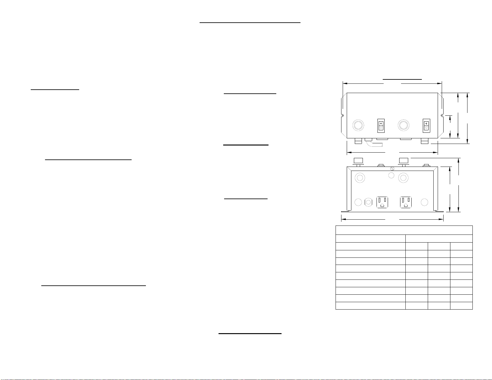
DIMENSIONS
RODIX, INC.
2316 23rd Ave., Rockford, IL 61104
Toll Free (800) 562-1868, FAX (815) 316-4701
E-mail [email protected]
www.rodix.com
FC-42-DC Plus 24-210.doc 10/8/2012 Page 2
S1 Programming Chart
Program Description S1 Switch Positions
SW3 SW4 SW5
Standard Program 0 0 0
Linear Pot Taper 1 0 0
0-20mA option 0 1 0
Empty Bowl Timer 1 1 0
Disable LVC 0 0 1
2-Speed Operation 1 0 1
30/40 Pulse Operation 0 1 1
Low Amplitude at “1” 1 1 1
4.0
2.0
4.04.8
9.0
8.0
8.75
4.5
1
88
FEEDER BOWL/HOPPER INTERLOCK
12 9
SWITCH
C)
LOW VOLTAGE INPUT SWITCHING
FC-90 PLUS SERIES
OFF/ON CONTROL GUIDE
(DC Voltage from PLC or FC-90 Plus
)
J1
711
A)
12 10
11 5
FC-40 PLUS SERIES TERM STRIP TB-2, INPUT
8
B)
TERM STRIP TB-2, OUTPUT
10 5
FC-40 PLUS SERIES TERM STRIP TB-2
12
+
OFF/ON CONTROL
FC-40 PLUS SERIES TERM STRIP TB-2
11 -
10-30 VDC INPUT VOLTAGE
See section 6 of the Application Note for more
details on the REMOTE OFF/ON CONTROL guide.
10 6
65
LOW CURRENT
SWITCH
7
9
7
96
3
PADDLE
2
Soft
TRANSFORMER
60Rev
Sig.
1
SIG
cw
-
1/8WMIN
100K
+
CONTROL
MAIN
POT
POWER
Min Max
11
68
8
12
60
SW3
SW5
External
-
JUMPER
+
SW4
5
211
9
4
7
710
3
12 6
5
1
10
9
LINE VOLTAGE
LOADG
TRIAC
TERM. STRIP
P/N 24-210
ACHOT
(SMALL)
CHASSIS
A1
FC-40 PLUS
OUTPUT POWER
FUSE
+
+
GATE
Pot Input
AUX FEATURE
AC COMMON
120
TB2
TERM. STRIP
TB2
J1
A2
(TALL)
4-20mA
+
TB1
-
-
S1
GND
TB1
Or #14
Wh #14
Bl #14
Bl #14
Bl #14
Vi #20
Wh #14
Wh #20
Direct
RUN
RUN
In ter l oc k
H1
-
+
-
-
+
Bl #14
Wh#14
Wh#14 Bl #14
Soft
TRANSFORMER
60Rev
1
Sig.
SIG
cw
-
100K
+
1/8WMIN
CONTROL
MAIN
POT
POWER
Min Max
11
68
8
12
60
External
SW3
SW5
-
JUMPER
+
SW4
59
2
7
1110
4
12
7
6
3 5
1
10
9
LINE VOLTAGE
LOAD
COM
TRIAC
G
TERM. STRIP
P/N 24-210
ACHOT
(SMALL)
A1
FC-40 PLUS
OUTPUT POWER
FUSE
CHASSIS
+
+
GATE
Pot Input
GND
AUX FEATURE
ACCOMMON
120
HOT
TB2
TERM. STRIP
TB2
A2
(TALL)
4-20mA
J1
+
TB1
-
INPUT POWER
S1
-
TB1
Or #14
GND
Wh #14
Bl #14
Bl #14
Bl #14
Vi #20
Wh #14
Wh #20
Direct
RUN In te r l oc k
RUN
H1
-
+
-
-
+
Wh#14
Bl #14
Bl #14
Wh#14
Bl #14
Bl #14
RODIX INC.
FEEDER CUBE
FC-40
Plus Series
WIRING DIAGRAM
MODEL INPUT VAC AMPS OUTPUT VDC
FC-42-DC
P
lu
s
120 VAC 10/5 0-90/130

RODIX, INC.
2316 23rd Ave., Rockford, IL 61104
Toll Free (800) 562-1868, FAX (815) 316-4701
Email [email protected]
www.rodix.com
FC-42-DC Plus 24-210.doc 3/15/2012 Page 3
RODIX SOLUTION
Good wiring practices for
avoiding electrical noise
problems.
Rodixcontrolshavebeendesignedwitha
high degree of immunity to electrical
noise;however,dependingon thecontrol
installation, electrical noise can cause
problems. These problems occur in less
than 1% of theproduct installations. Most
electrical noise problems can be avoided
by following some simple guidelines.
Good wiring practices need to be used to
prevent electrical noise from interfering
with your control’s operation. Another
name for electrical noise is Electro-
Magnetic Interference (EMI).
Symptoms of Electrical Noise
The symptoms of electrical noise would
appear as follows: a brief pause ora brief
“bump” in the vibratory feeder’s output
that the control automatically recovers
from. In rare cases the control will either
stop operating or run continuously at full
power in 120 pulse mode until the power
switch is slowly cycled OFF and ON.
Sources of Electrical Noise
Electrical noise is generated by devices
like relay coils, solenoid valves,
contactors, servo motors, and variable
frequency inverter drives. The electrical
noise is then transferred to another
device by one of three ways. The noise
could be conducted through the power
wires, or capacitivelycoupled fromwireto
adjacent wire, or it istransmitted from the
wires of a nearby noise source.
Solutions for Electrical Noise
1. Use shielded wires for all I/O (Input /
Output) signals. The I/O signals may
include: 4-20mA input, Run input, Sensor
input, 0-5VDC input, Interlock input or
AUX output. The shield “drain” wire
should be tied to the chassis in the Rodix
control. The drain wire should be kept
shorter than 2”. Please see the enclosed
picture.
Example of a “drain” wire termination
2. Never run I/O signal wires in the same
conduit or raceway as AC power lines
such as wires to motors, solenoids,
heaters, welders and Rodix controls, etc.
3. I/O wires within an enclosure should
be routed as far away as possible from
relays, solenoids, transformers, power
wiring and other noisy equipment. Keep
the I/O signal wires separate from the
control’s input and output power wiring.
Secure the wires in place.
4. Whenever relays or solenoid valves
are used, install a Snubber on them to
reduce electrical noise. Use a diodeon a
DC coil. Use a RC Snubber on an AC
coil.
5. In extremely high EMI environments,
Power Line Filters and ferrite beads can
be effective. Install ferrite beads on I/O
signal wires as close as possible to the
circuit board terminal strip. Loop the wire
through the bead several times or use
several beads on each wire for additional
protection.
RODIX, INC.
2316 23rd Avenue, Rockford, IL 61104
Toll Free (800) 562-1868, FAX (815) 316-4701
E-mail custserv[email protected]
www.rodix.com
2000,2011 RODIX INC. GoodWiring10/25/2011
RODIX INC.
FEEDER CUBE


RODIX SOLUTION
.408
Drain
Wire
RELAY
COILSNUBBER
VAC
104M06QC47
QUENCH-ARC
RECTIFIER
DIODE RELAY
COIL
1N4006
VDC
+
-

This manual suits for next models

2

Other Rodix Industrial Equipment manuals

Rodix FEEDER CUBE VF-393 User manual

Rodix

Rodix FEEDER CUBE VF-393 User manual

Rodix FEEDER CUBE VF-3-2 User manual

Rodix

Rodix FEEDER CUBE VF-3-2 User manual

Rodix FC-40 Plus Series Setup guide

Rodix

Rodix FC-40 Plus Series Setup guide

Rodix FEEDER CUBE CE-40 Plus Series Setup guide

Rodix

Rodix FEEDER CUBE CE-40 Plus Series Setup guide

Rodix FEEDER CUBE FC-40 Plus Series Setup guide

Rodix

Rodix FEEDER CUBE FC-40 Plus Series Setup guide

Rodix FEEDER CUBE FC-40 Plus Series Setup guide

Rodix

Rodix FEEDER CUBE FC-40 Plus Series Setup guide

Rodix FC-40 Plus Series Setup guide

Rodix

Rodix FC-40 Plus Series Setup guide

Rodix Plus Series User manual

Rodix

Rodix Plus Series User manual

Rodix FEEDER CUBE FC-40 Plus Series Setup guide

Rodix

Rodix FEEDER CUBE FC-40 Plus Series Setup guide

Rodix FEEDER CUBE FC-40 Plus Series Setup guide

Rodix

Rodix FEEDER CUBE FC-40 Plus Series Setup guide

Rodix FEEDER CUBE VF-9 User manual

Rodix

Rodix FEEDER CUBE VF-9 User manual

Rodix FEEDER CUBE FC-40 Plus Series Setup guide

Rodix

Rodix FEEDER CUBE FC-40 Plus Series Setup guide

Rodix FEEDER CUBE FC-100 Plus Series Setup guide

Rodix

Rodix FEEDER CUBE FC-100 Plus Series Setup guide

Rodix FEEDER CUBE VF Series User manual

Rodix

Rodix FEEDER CUBE VF Series User manual

Rodix FEEDER CUBE VF-9-OR User manual

Rodix

Rodix FEEDER CUBE VF-9-OR User manual

Rodix FC-100-PLC Plus Setup guide

Rodix

Rodix FC-100-PLC Plus Setup guide

Rodix FEEDER CUBE FC-90 Plus Series User manual

Rodix

Rodix FEEDER CUBE FC-90 Plus Series User manual

Rodix FEEDER CUBE FC-70 Series Setup guide

Rodix

Rodix FEEDER CUBE FC-70 Series Setup guide

Rodix 24-210 User manual

Rodix

Rodix 24-210 User manual

Rodix FEEDER CUBE FC-40 Plus Series Setup guide

Rodix

Rodix FEEDER CUBE FC-40 Plus Series Setup guide

Rodix FEEDER CUBE VF-3-3 User manual

Rodix

Rodix FEEDER CUBE VF-3-3 User manual

Rodix FEEDER CUBE FC-40 Plus Series Setup guide

Rodix

Rodix FEEDER CUBE FC-40 Plus Series Setup guide

Rodix Autotune Series User manual

Rodix

Rodix Autotune Series User manual

Rodix FEEDER CUBE FC-40 Plus Series Setup guide

Rodix

Rodix FEEDER CUBE FC-40 Plus Series Setup guide

Popular Industrial Equipment manuals by other brands

ABB HT607956 Operation manual

ABB

ABB HT607956 Operation manual

Herzog NE Installation and service instructions

Herzog

Herzog NE Installation and service instructions

ABB HT604703 Operation manual

ABB

ABB HT604703 Operation manual

Dorner 75M-V1-3211-05 Application guide

Dorner

Dorner 75M-V1-3211-05 Application guide

MBO SVC 525C Translation of the original operating manual

MBO

MBO SVC 525C Translation of the original operating manual

TLV JH3LH-X instruction manual

TLV

TLV JH3LH-X instruction manual

SCHUNK TENDO SVL Assembly and operating manual

SCHUNK

SCHUNK TENDO SVL Assembly and operating manual

GBC 34.0136.00 1500W manual

GBC

GBC 34.0136.00 1500W manual

SEW-Eurodrive WPU 1001 Installation and operating instructions

SEW-Eurodrive

SEW-Eurodrive WPU 1001 Installation and operating instructions

TMG TMG-SBC60 product manual

TMG

TMG TMG-SBC60 product manual

Siemens FLENDER GHZP Assembly and operating instructions

Siemens

Siemens FLENDER GHZP Assembly and operating instructions

National Instruments NI 9475 Getting started

National Instruments

National Instruments NI 9475 Getting started

Danfoss FT1555-BM230 Operator's manual

Danfoss

Danfoss FT1555-BM230 Operator's manual

AMBIC POWER FOAMER operating instructions

AMBIC

AMBIC POWER FOAMER operating instructions

IKA RC 5 control operating instructions

IKA

IKA RC 5 control operating instructions

CARLO GAVAZZI Dupline Design and installation guide

CARLO GAVAZZI

CARLO GAVAZZI Dupline Design and installation guide

Empire EMT-7R Instruction & parts manual

Empire

Empire EMT-7R Instruction & parts manual

ABB HT562485 Operation manual

ABB

ABB HT562485 Operation manual

manuals.online logo
manuals.online logoBrands
  • About & Mission
  • Contact us
  • Privacy Policy
  • Terms and Conditions

Copyright 2025 Manuals.Online. All Rights Reserved.