Packd C4 Series User manual

ASSEMBLY & INSTALLATION GUIDE
C4 Series Shelving
Fits:
Full Sized Low Roof Vans

2 | C4 A s s e m b l y & I n s t a l l a t i o n G u i d e
Contents
ASSEMBLY INSTRUCTIONS ............................................................................................................................3
1PREPARATION ...................................................................................................................................3
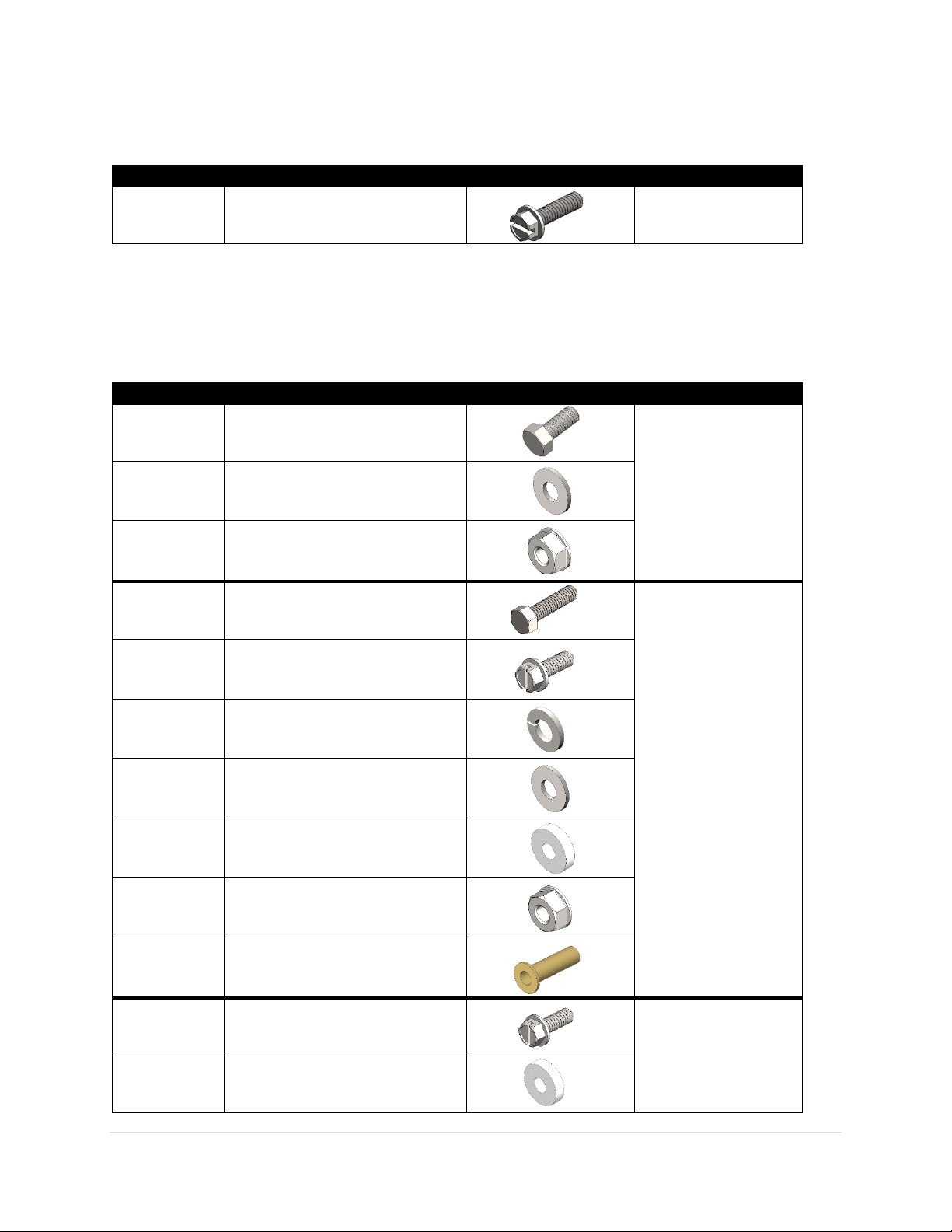
2ASSEMBLY FASTENER KIT..................................................................................................................4
3INSTALL FASTENER KIT ......................................................................................................................4
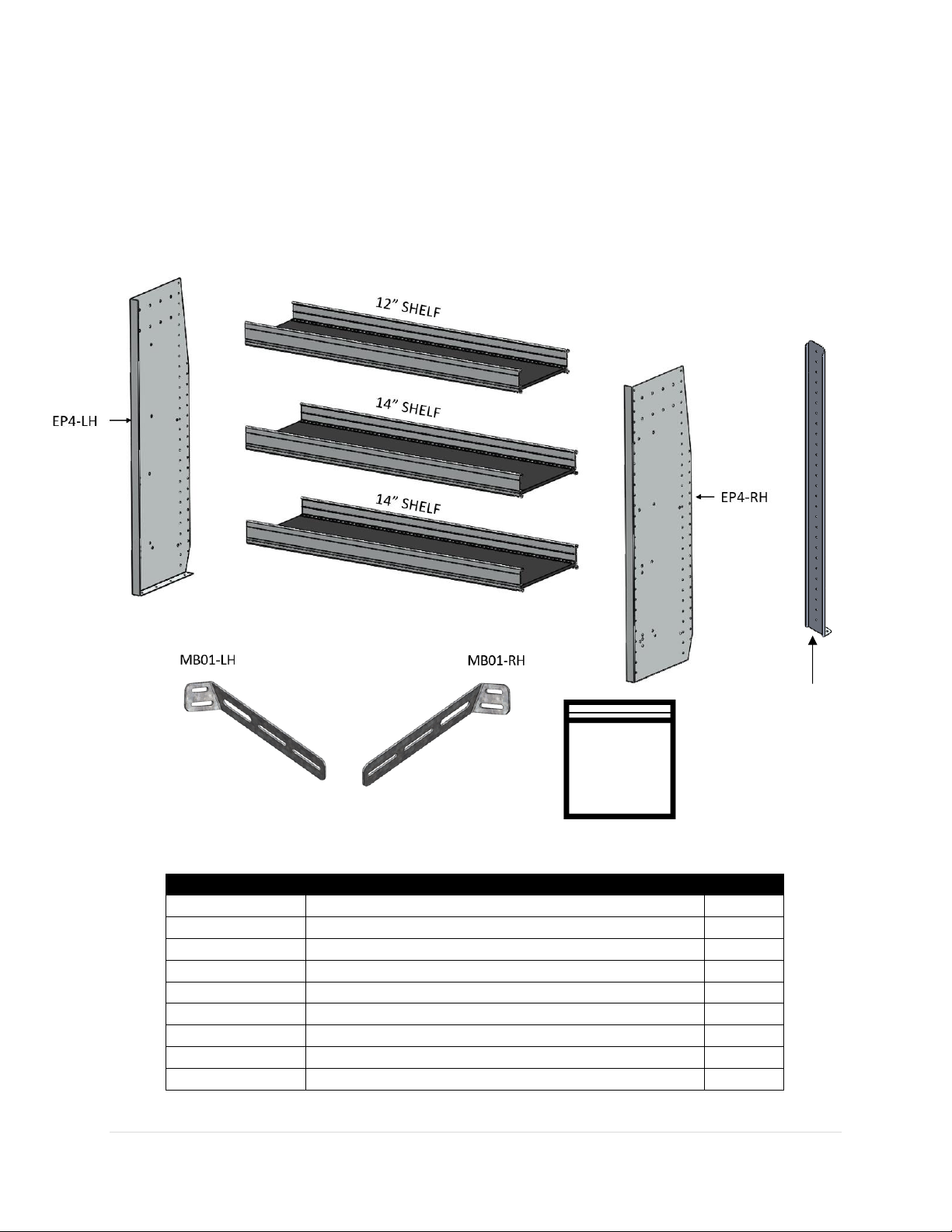
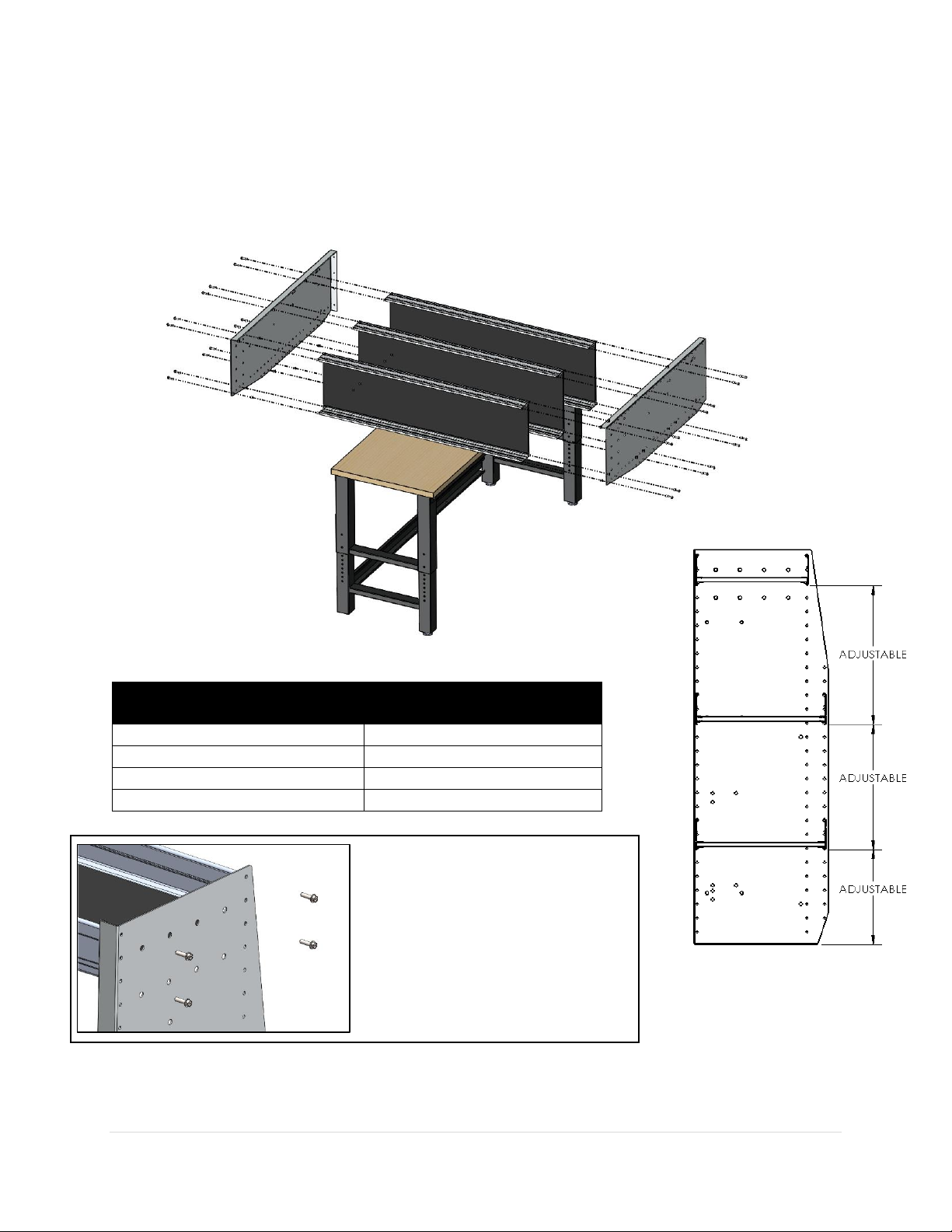
4SHELF ASSEMBLY...............................................................................................................................5
INSTALLATION INSTRUCTONS.......................................................................................................................6
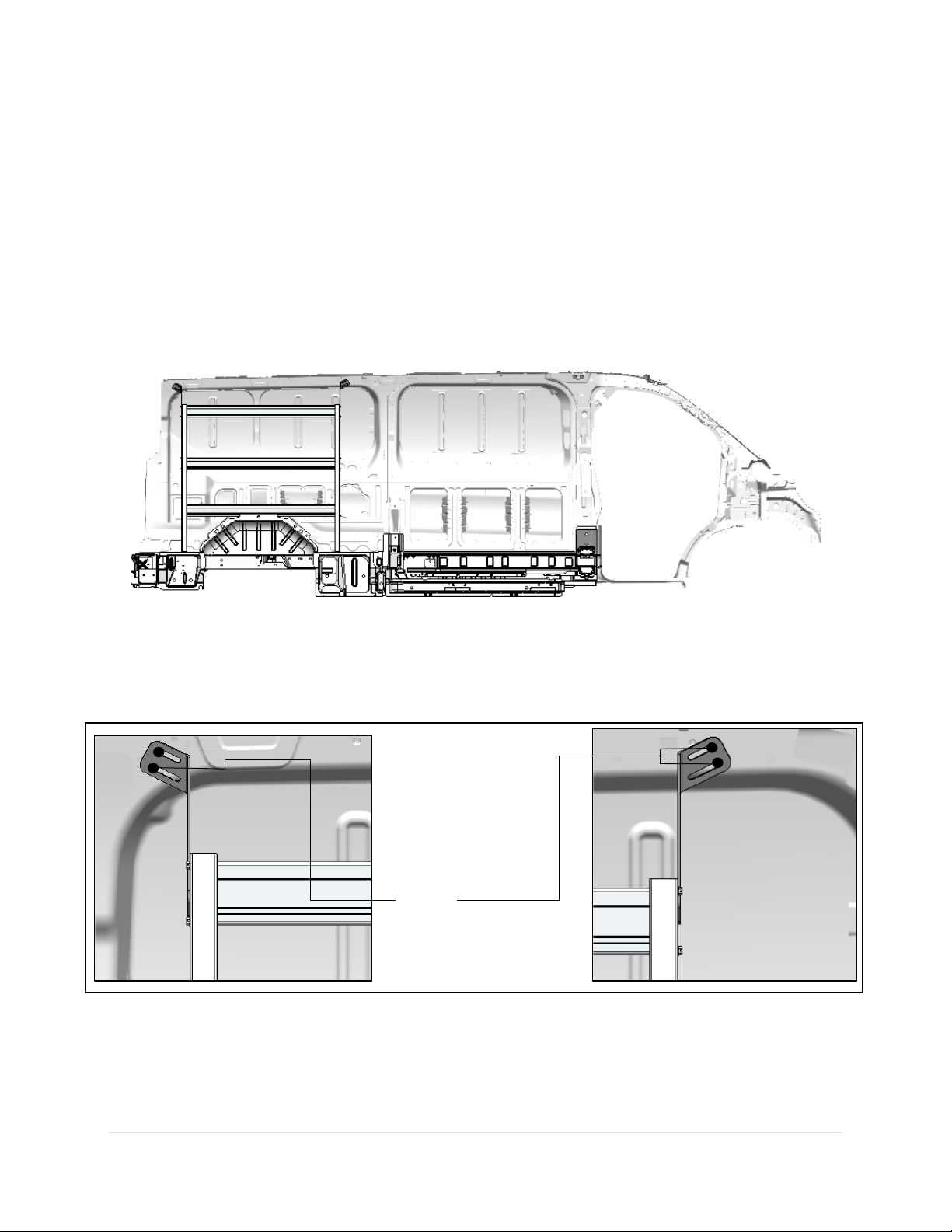
1FASTENING BRACKETS TO END PANELS............................................................................................6
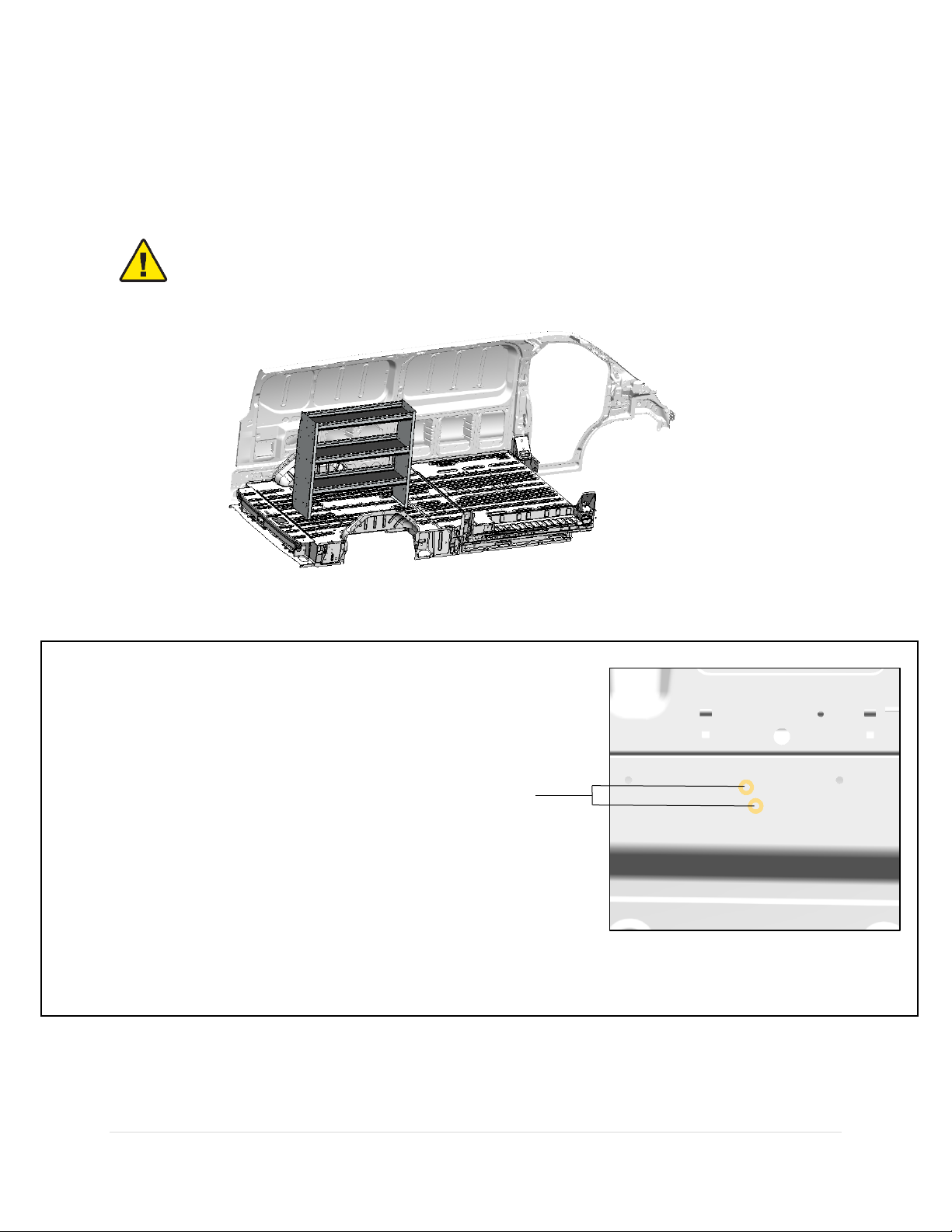
2MARKING HOLES FOR PLUS NUTS.....................................................................................................7
3INSTALLING PLUS NUTS.....................................................................................................................8
4FASTENING SHELF UNIT TO THE WALL ...........................................................................................10
5FASTENING SHELF UNIT TO THE FLOOR..........................................................................................12
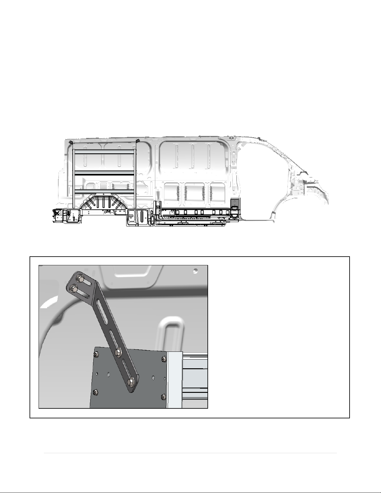
6INSTALLING CENTER SUPPORT........................................................................................................14
Required Items
2 People (To Lift Shelf Unit)
3/8” Drill Bit
3/8” Nut Driver Bit
1/2” Drill Bit w/ Drill Collar (Set at 1/2")
1/2" Nut Driver Bit
9/16” Wrench
1” Hole Saw
Plus Nut Tool or Plus Nut Gun (5/16”)
Marker
Cordless Drill
Cordless Impact Driver
Tape Measure
Large Square

3 | C4 A s s e m b l y & I n s t a l l a t i o n G u i d e
ASSEMBLY INSTRUCTIONS
1PREPARATION
Unpack components and compare to the Bill of Materials. Ensure that all of the parts are present.
BILL OF MATERIALS
Part Number
Description
Quantity
EP4-LH
SFO Aluminum LH End Panel 45” x 16”
1
EP4-RH
SFO Aluminum LH End Panel 45” x 16”
1
12” Shelf
Shelf Tray Assembly, 12”
1
14” Shelf
Shelf Tray Assembly, 14”
2
MB01-LH
Shelf Mounting Bracket, LH
1
MB01-RH
Shelf Mounting Bracket, RH
1
CS4
LR Centre Support (For Shelf Units 72” or longer)
1
Assembly Fastener Kit
1
Install Fastener Kit
1
FASTENERS
CS4
For Shelf Units
72” or longer

4 | C4 A s s e m b l y & I n s t a l l a t i o n G u i d e
2ASSEMBLY FASTENER KIT
3INSTALL FASTENER KIT
Quantity
Description
Image
Purpose
32
Hex Washer Head Screw
#14 x 1”
Fastening Shelf Trays
to the End Panels
Quantity
Description
Image
Purpose
4
Hex Bolt
5/16-18 x 3/4
Fastening the Shelf
Mounting Brackets
to the End Panels
4
Flat Washer
5/16
4
Serrated Nut
5/16-18
4
Hex Bolt
5/16-18 x 1-1/4
Fastening the Shelf
Assembly to the
structure of the
vehicle
8
Hex Washer Head Screw
#14 x 3/4
4
Lock Washer
5/16
4
Flat Washer
5/16
6
1/4” Nylon Spacer
4
Serrated Nut
5/16-18
4
Plus Nut
5/16
6
Hex Washer Head Screw
#14 x 3/4
Installing Centre
Support (For Shelf
Units 72” or Longer)
2
1/4” Nylon Spacer

5 | C4 A s s e m b l y & I n s t a l l a t i o n G u i d e
4SHELF ASSEMBLY
•Position shelf trays on a work bench. Fasten the End Panels to the Shelf Trays using the
hardware provided.
•Make sure the bench is clean and smooth to minimize scratches.
VEHICLE
MINIMUM CLEARANCE
(OVER WHEEL WELL)
Mercedes Benz Sprinter
13”
Ford Transit
11.5”
Ram Promaster
17”
GMC Savana
12”
Tools Used:
Cordless Impact Driver
3/8” Nut Driver Bit
Hardware Used:
24 x Hex Washer Head Screw #14 X 1”
•Set shelf heights as desired –refer to table
below for minimum wheel well clearance.

6 | C4 A s s e m b l y & I n s t a l l a t i o n G u i d e
INSTALLATION INSTRUCTONS
1FASTENING BRACKETS TO END PANELS
1. Lift assembled shelf unit into vehicle and place it in the desired location.
2. Place the mounting brackets so that they align with the horizontal rim of the vehicle as shown.
3. Make 2 marks in the slots of the mounting bracket onto the end panel of the shelf unit.
4. Use a 3/8” drill bit to drill out the holes for mounting the mounting brackets onto the end
panels.
5. Fasten the mounting brackets onto the end panels.
Tools Used:
Cordless Impact Driver
Cordless Drill
1/2” Nut Driver Bit
3/8” Drill Bit
Marker
Hardware Used:
4 x Hex Bolt 5/16-18 x .75”
4 x 5/16 Flat Washer
4 x Serrated Nut 5/16-18
Horizontal Rim
MB01-LH
MB01-RH

7 | C4 A s s e m b l y & I n s t a l l a t i o n G u i d e
2MARKING HOLES FOR PLUS NUTS
Mark Plus Nut Locations
Once the mounting brackets are secured to the end panels, marks can be made for installing Plus Nuts
onto the vehicle. (See page 11 for vehicles with Wall Kits)
Mark 4 holes onto the
horizontal rim of the
vehicle as shown
Tools:
Marker
Mark

8 | C4 A s s e m b l y & I n s t a l l a t i o n G u i d e
3INSTALLING PLUS NUTS
1. Lift shelf unit so that it is out of the way.
2. Drill holes using a 1/2" drill bit with a collar to stop drill at 1/2" depth.
WARNING: Check for wiring or gas tanks BEFORE drilling into floors, pillars, headliners, or walls.
Using a 1/2" drill bit with a 1/2" Drill Collar, drill
out all of the marks from the previous step. Install
Plus Nuts into drilled holes. Only use Plus Nuts in
places where Bolts and Nuts cannot be used.
Tools:
Cordless Drill
1/2" Drill Bit with Drill Collar (Set to 1/2" Depth)
Hardware:
4 x 5/16” Plus Nuts
Plus Nuts

9 | C4 A s s e m b l y & I n s t a l l a t i o n G u i d e
AUsing Plus Nut Gun: (If available- otherwise see B below)
•Place 2 drops of air tool oil into the air fitting regularly.
•Ensure that there is anti-seize on the Plus Nut Gun threads at all times.
•Thread a Plus Nut onto the threads of the gun, then place bolt and Plus Nut through pre-
drilled hole.
•Pull trigger of Plus Nut Gun to compress Plus Nut into the material until the noise changes on
the gun.
•Reverse direction on gun to unscrew Bolt from the Plus Nut.
FORWARD
REVERSE
Assemble the Plus
Nut Tool as shown.
Tools:
9/16” Wrench
Hardware:
Plus Nut Tool
Fasten Plus Nut to vehicle:
•Insert Plus Nut into
hole.
•Hold Nut with
wrench.
•Tighten bolt until
Plus Nut clamps the
vehicle body metal
tightly.
STEP 1
STEP 2
BUsing Plus Nut Tool:
Tools:
Cordless Impact Driver
1/2" Nut Driver Bit
9/16” Wrench
Hardware:
4 x 5/16” Plus Nuts
Plus Nut Tool

10 | C4 A s s e m b l y & I n s t a l l a t i o n G u i d e
4FASTENING SHELF UNIT TO THE WALL
Without Wall Kit
Lift the assembled shelf unit back into place ensuring that the slots in the mounting brackets line up with
the Plus Nuts in the wall.
Fasten the Shelf Unit to the wall.
Tools Used:
Cordless Impact Driver
3/8” Nut Driver Bit
Hardware Used:
4 x 5/16-18 x 1-1/4” Hex Bolt
4 x 5/16 Flat Washer
4 x 5/16 Lock Washer
4 x 5/16 Plus Nut

11 | C4 A s s e m b l y & I n s t a l l a t i o n G u i d e
With Wall Kit
1. Make 4 marks using the slots of the mounting brackets onto the wall kit.
2. Use a 1” hole saw to carefully cut out holes in the wall kit at the desired fastener location (in the
locations where plus nuts were installed).
3. Use a 1/2" drill with a collar set to a 1/2" depth to drill out the holes.
4. Install the Plus Nuts into the holes. (See page 9)
5. Fasten the Shelf Unit to the vehicle.
Fasten the Shelf Unit to the wall.
Tools Used:
Cordless Impact Driver
Cordless Drill
1” Hole Saw
1/2" Drill Bit with Drill Collar (Set to 1/2" Depth)
1/2” Nut Driver Bit
Hardware Used:
4 x 5/16-18 x 1-1/4” Hex Bolt
4 x 5/16 Flat Washer
4 x 5/16 Lock Washer
4 x 5/16 Plus Nut

12 | C4 A s s e m b l y & I n s t a l l a t i o n G u i d e
5FASTENING SHELF UNIT TO THE FLOOR
With Floor Kit
Fasten the Shelf Unit to the subfloor
using square to position front 90° to
the floor.
Tools Used:
Cordless Impact Driver
3/8” Nut Driver Bit
Large Square
Hardware Used:
8 x Hex Washer Head Screw #14 x 3/4”

13 | C4 A s s e m b l y & I n s t a l l a t i o n G u i d e
Without Floor Kit
Fasten the Shelf Unit to the floor using
square to position front 90° to the
floor. Use 1/4 Nylon Spacers where
necessary.
Tools Used:
Cordless Impact Driver
3/8” Nut Driver Bit
Large Square
Hardware Used:
8 x Hex Washer Head Screw #14 x 3/4”
1/4 Nylon Spacer
1/4 Nylon Spacers

14 | C4 A s s e m b l y & I n s t a l l a t i o n G u i d e
6INSTALLING CENTER SUPPORT
For Shelving Units 72” or longer, a Center Support will need to be installed.
With Floor Kit
•Measure and mark the center of the
Shelving Unit.
•Place the Center Support so that it is
centered on the Shelving Unit using square
to locate it perpendicular to the floor.
•Fasten Center Support to Shelving Unit.
•Fasten Center Support to Subfloor.
Tools Used:
Cordless Impact Driver
3/8” Nut Driver Bit
Marker
Tape Measure
Large Square
Hardware Used:
5 x Hex Washer Head Screw #14 x 3/4”

15 | C4 A s s e m b l y & I n s t a l l a t i o n G u i d e
Without Floor Kit
•Measure and mark the center of the
Shelving Unit.
•Place the Center Support so that it is
centered on the Shelving Unit using square
to locate it perpendicular to the floor.
•Fasten Center Support to Shelving Unit.
•Fasten Center Support to floor. Use 1/4
Nylon Spacers where necessary.
Tools Used:
Cordless Impact Driver
3/8” Nut Driver Bit
Marker
Tape Measure
Large Square
Hardware Used:
5 x Hex Washer Head Screw #14 x 3/4”
2 x 1/4” Nylon Spacer
1/4” Nylon Spacer
Table of contents
Popular Outdoor Cart manuals by other brands

Wolfcraft
Wolfcraft TS 2500 Translation of the original operating instructions

PEERLESS
PEERLESS HCC101 manual

Chauvet
Chauvet NIMBUS CART Quick reference guide

LDI Spaces
LDI Spaces SAFCO Onyx 5212 Assembly instructions

Cornwell Tools
Cornwell Tools Pro CTBMM500BKNGE Assembly instructions

Spectrum Industries
Spectrum Industries Cloud32 owner's manual

Vestil
Vestil CART-2000 Operating instructions & parts manual

Premier Mounts
Premier Mounts LFC-L installation guide

Enwork
Enwork ZORI MEDIA CART CASTER PLATE Assembly instructions

HydroSure
HydroSure HS2WHC Assembly instructions

IKH
IKH XPH360A instruction manual

Hot Max
Hot Max WC100 Assembly instructions and parts list