PacLights FHZL Series User manual

INSTALLATION GUIDE FHZL Series LED Hazardous Location Lighting
Instructions and specifications are subject to change at any time without notice. Copyright© 2021 PacLights All Rights Reserved Page 1 of 5
Need help? (800) 988 -6386 Email: CS@PacLights.com Website: www.PacLights.com
PL_INST_FHZL_v0
FHZL THREADED PIPE MOUNTING & CONDUIT INSTALLATION
IMPORTANT
READ CAREFULLY BEFORE INSTALLING FIXTURE. RETAIN THESE INSTRUCTIONS FOR FUTURE REFERENCE.
PacLights fixtures must be wired in accordance with the National Electrical Code and all applicable local codes. Proper grounding is required for safety.
THIS PRODUCT MUST BE INSTALLED IN ACCORDANCE WITH THE APPLICABLE INSTALLATION CODE BY A PERSON FAMILIAR
WITH THE CONSTRUCTION AND OPERATION OF THE PRODUCT AND THE HAZARDS INVOLVED.
WARNINGS:
• MIN 90°C SUPPLY CONDUCTOR. THIS PRODUCT MUST BE INSTALLED IN ACCORDANCE WITH THE APPLICABLE
INSTALLATION CODE BY A PERSON FAMILIAR WITH THE CONSTRUCTION AND OPERATION OF THE PRODUCT AND THE
HAZARDS INVOLVED.
• Make certain power is OFF before installing or maintaining fixture. No user serviceable parts inside.
• To prevent wiring damage or abrasion, do not expose wiring to edges of sharp objects.
CAUTION:
• For proper weatherproof function all gaskets must be seated properly and all screws inserted and tightened firmly. Apply weatherproof silicone
sealant around the edge of the Back Box and/or Junction Box. This is especially important with an uneven wall surface. Silicone all plugs and
unused conduit entries.
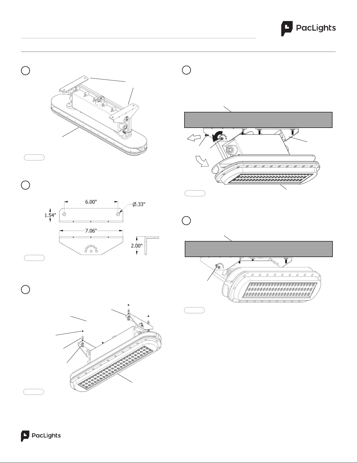
FIG. 1
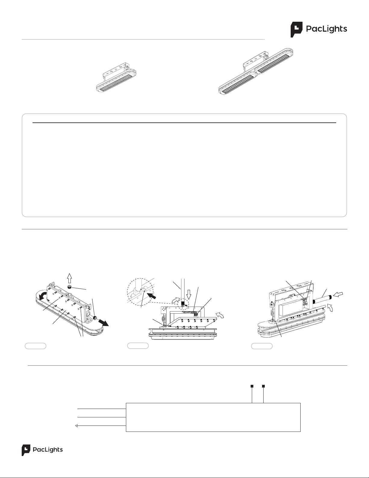
FHZL 040 FHZL 080/120
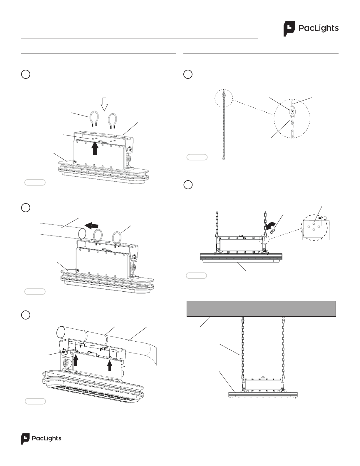
The FHZL Threaded Pipe Mount is installed from the top and the Conduit from the side of the fixture with the wiring. The FHZL Series Wiring requires
the Driver Box Cover to be removed. Remove the 3/4” NPT Nut (side or top of fixture), the Screw Cap Covers and loosen the Screws (Fig. 1). Open the
Driver Box Cover and the Lanyard will hold the Cover to prevent it from falling o. Pull the Wiring (Aluminum or Copper conductors) through one of the
theaded holes and connect to the Terminal Block (Fig. 2 or 3). Re-install the Driver Box Cover, Pipe at the top or Conduit at the side (Both Not Included)
in place of the 3/4” NPT Nut (Use silicone gel around the threads for water tight seal), Screws, and Screw Caps in the reverse order. For top installation,
tighten the fixing Screw to the Pipe (Fig. 2).
Connect the ACL and the ACN from the FHZL Fixture to the conduit with the AC power Supply Cable. Follow the Wiring Diagram provided.
AC POWER SUPPLY
FHZL DRIVER
GRAY (-)
PURPLE (+)
HOT [BLACK]
NEUTRAL [WHITE]
GROUND [GREEN]
WIRING DIAGRAM
DIM
INPUT
SCREWS
SCREW
CAPS
FIG. 2
LANYARD
3/4” NPT
NUTS
TERMINAL
BLOCK WIRING
DRIVER BOX
COVER
CONDUIT
PIPE
TERMINAL
BLOCK
WIRING
FIG. 3
SCREW
LANYARD

INSTALLATION GUIDE FHZL Series LED Hazardous Location Lighting
Instructions and specifications are subject to change at any time without notice. Copyright© 2021 PacLights All Rights Reserved Page 2 of 5
Need help? (800) 988 -6386 Email: CS@PacLights.com Website: www.PacLights.com
PL_INST_FHZL_v0
FHZL TRUNNION MOUNT (OPTIONAL)
The Optional FHZL Trunnion Mount is available for all FHZL fixtures
(Fig. 4). The FHZL Trunnion Mount can be used to mount the FHZL
fixture to a ceiling or a wall.
1
2
FIG. 4
FHZL FIXTURE
FHZL TRUNNION
MOUNT
Instead of having the fixture directly mounted at a fixed position
the FHZL fixture can be adjusted by loosening the large Screws
and removing the smaller Screws at the sides of the of the Trunnion
Mount. This allows the fixture to rotate to the desired tilt angle (30-
60-90 degrees) to aim at a specific position (Fig. 7).
4
FIG. 7
Fasten the Trunnion Mount to the mounting surface (Wall or Ceiling)
with the appropriate bolts (may vary depending on the mounting
surface) by a certified personnel (Fig. 6). Refer to #2. for dimensions.
3
FIG. 5
FIG. 6
FHZL FIXTURE
WALL / CEILING
FHZL FIXTURE
FHZL Trunnion Mount dimensions (Fig. 5).
ANCHOR STUDS
TRUNNION MOUNT
TRUNNION
MOUNT WALL / CEILING
SCREWS
NUTS & WASHERS
~
HOLES
Align the Trunnion Mount hole to the FHZL fixture hole. Re-insert
and tighten the Screws (Fig. 8).
5
WALL / CEILING
FIG. 8 SCREWS

INSTALLATION GUIDE FHZL Series LED Hazardous Location Lighting
Instructions and specifications are subject to change at any time without notice. Copyright© 2021 PacLights All Rights Reserved Page 3 of 5
Need help? (800) 988 -6386 Email: CS@PacLights.com Website: www.PacLights.com
PL_INST_FHZL_v0
FIG. 11
The Optional Surface Mount can be used for all the FHZL fixtures
(Fig. 9).
FHZL SURFACE MOUNT (OPTIONAL)
FIG. 13
3
4
FIG. 10
FHZL FIXTURE
SURFACE
MOUNT
Fasten the Surface Mount to the mounting surface (Wall or
Ceiling) with the appropriate bolts (may vary depending on the
mounting surface) by a certified personnel (Fig. 11). Refer to #2. for
dimensions.
FIG. 12
Instead of having the fixture directly surface mounted at a fixed
position the FHZL fixture can be adjusted by loosening the large
Screws and removing the smaller Screws at the sides of the of the
Surface Mount. This allows the fixture to rotate to the desired tilt
angle to aim at a specific position (Fig. 12).
Align the Surface Mount hole to the FHZL fixture hole. Re-insert
and tighten the Screws (Fig 13).
5
1
FHZL Surface Mount dimensions (Fig. 10).
2
FHZL FIXTURE
FIG. 9
WALL / CEILING
ANCHOR STUDS
NUTS & WASHERS
SURFACE
MOUNT
HOLES
~
WALL / CEILING
SCREWS
WALL / CEILING
SURFACE
MOUNT
SCREWS
FHZL FIXTURE

INSTALLATION GUIDE FHZL Series LED Hazardous Location Lighting
Instructions and specifications are subject to change at any time without notice. Copyright© 2021 PacLights All Rights Reserved Page 4 of 5
Need help? (800) 988 -6386 Email: CS@PacLights.com Website: www.PacLights.com
PL_INST_FHZL_v0
FHZL POLE MOUNT (OPTIONAL)
The Optional Pole Mount can be used for all the FHZL fixtures that
fit directly onto the Trunnion Mount (Fig. 14). Round Poles (Ø2.4”
Max) will fit the U-Bolts provided. The arm length of the Pole needs
to be the more than the length of the fixture to clear the vertical
portion of the Pole.
1
FIG. 14
FHZL FIXTURE
TRUNNION MOUNT
NUTS
U-BOLT
Slide the FHZL fixture with the U-Bolts and Nuts partially fastened
onto the Round Pole (Fig. 15).
2
Tighten the nuts to the U-Bolts and tighten the Wing Nut Screw
from the bottom of the Trunnion Mount to secure the Pole (Fig. 16).
3
FIG. 15
POLE
WING NUT
SCREW
FIG. 16
FHZL CHAIN MOUNT (OPTIONAL)
The Optional Chain Mount can be used for all the FHZL fixtures.
The Chain Mount includes the two Chains, Carabiners at each end,
and Anchor Studs (Round Eye Nut Not Included) (Fig. 17).
1
FHZL FIXTURE
ROUND
EYE NUT
ANCHOR
STUD
CARABINER
CHAIN
FIG. 17
FIG. 18
HOLE
After the Anchor Studs are secured into the ceiling and the Chains
are hung from the Eye Nuts, at the other end of the Chain, the
Carabiners can be attached to the sides of the FHZL fixture at the
top holes (Fig. 18).
2
CARABINER
U-BOLT
POLE
U-BOLT
FHZL FIXTURE
CEILING
FHZL FIXTURE

INSTALLATION GUIDE FHZL Series LED Hazardous Location Lighting
Instructions and specifications are subject to change at any time without notice. Copyright© 2021 PacLights All Rights Reserved Page 5 of 5
Need help? (800) 988 -6386 Email: CS@PacLights.com Website: www.PacLights.com
PL_INST_FHZL_v0
FHZL WIRE GUARD (OPTIONAL)
The Optional Wire Guard can be placed on all of the FHZL fixtures
(Fig. 19). The FHZL 040 requires one Wire Guard and the FHZL
080/120 requires two Wire Guards.
1
FIG. 20
FHZL FIXTURE
SCREWS
WIRE
GUARD
FHZL SAFETY RETENTION CABLE
1
The FHZL Safety Retention Cable is necessary for the all FHZL
fixtures (Fig. 21).
FIG. 19
The Wire Guard(s) should be placed on the fixture Cover prior to
the FHZL fixture installation. Install the Screws to hold the Wire
Guard(s) in place for each fixture Cover (Fig. 20).
2
FIG. 21
FIG. 22
2
Attach the Safety Retention Cable to the FHZL fixture as shown
below (Fig. 22). There are holes located next to the Driver Box on
either side of the fixture.
3
Attach the other side of the Safety Retention Cable to the mounting
structure, i.e. Beam (Fig. 23).
FIG. 23
WIRE
GUARD
FIXTURE
COVER
RETENTION CABLE
RETENTION CABLE
FHZL FIXTURE
RETENTION CABLE
BEAM
CARABINER
DRIVER BOX
CARABINER
This manual suits for next models
3
Other PacLights Light Fixture manuals
Popular Light Fixture manuals by other brands

Nortek
Nortek GoControl LB65R6Z-1 instructions

General Mfg
General Mfg THE LITE 9032-7037 Care and operation instructions

Commercial Electric
Commercial Electric SKU 445-997 instruction manual

Lightolier
Lightolier CFA2GPF228 specification

FC LIGHTING
FC LIGHTING FCSL101-FCSL106 installation instructions

Chauvet
Chauvet Followspot 1200 quick start guide

Teknoware
Teknoware Trispot TWT75 Installation and Maintenance

Westcott
Westcott FJ400 user manual

Triarch
Triarch 32092 installation instructions

LITELINE
LITELINE ATK A Series quick start guide

Cooper Lighting
Cooper Lighting AMETRIX SRR installation instructions

RSA Lighting
RSA Lighting Continuous Channel V90163 installation instructions