4
B1d.1
4/06
Supercedes 8/05
PACOPACO
PACOPACO
PACO
PUMPS
groovedbefore the concrete sets to providea suit-
ablebonding surface for grout. Anchor bolts should
be set in pipe sleeves for positioning allowance, as
showninFig. 2a. Allow enough bolt length for grout,
lower base plate flange, nuts and washers. Allow
thefoundationtocureseveral days before proceed-
ing with pump installation.
F. SECURING THEBASE PLATE
•After the concrete pad has been poured and set,
lowerthepumpbase plate over the anchor bolts and
rest it on loose adjustment wedges or shims placed
G. PIPING-GENERAL
• Do not use pump as a support for piping! Use
pipehangers or other supports atproper intervals to
providecompletepiping support near the pump.
• Bothsuction and dischargepiping should be inde-
pendentlysupportedand properly aligned to insure
no strain is transmitted to the pump when the bolts
aretightened. Use of expansion jointsor vibration
padsdoes not preclude the need to properly support
thepiping.
• Do not spring or force piping when making
connections!
• Make sure all piping is as direct as possible.
• Avoid unnecessary bends and fittings.
H. SUCTION (INLET) PIPING
The sizing and installation of suction piping is particu-
larly important. It must be selected and installed in a
manner that minimizes pressure loss and permits suffi-
cientliquid flow into the pumpduring starting and opera-
tion. Many NPSH problems can be traced directly to
improperdesignof suction piping systems. Observe the
followingprecautionswhen installing piping:
•Suction piping should be as direct as possible, and
ideally the length should be at least ten times the
pipediameter. Short suction piping canbethesame
diameter as the suction opening. Longer piping
shouldbe one or two sizes larger (depending on
length),reducingtothediameter of the suction open-
ingnear the pump.
•Use an eccentric reducer, with the eccentric side
down, as shown in (Fig. 3a on page 5) when
reducingpipe diameter to the diameter of the pump
suctionopening.
• At no time should suction piping be smaller in
diameter than the pump suction opening.
•Horizontalsuction lines should follow aneven
gradient, if possible. A gradual upward slope to the
pump is recommended for suction lift conditions,
andagradualdownward slope for positive suction
head.
•Avoidany high points, such aspipe loops, as shown
in (Fig. 4a on page 5), that may create air pockets
and throttle the system or produce erratic
pumping.
24" along each side.
•Shimsorwedgesmust be placed to raise the bottom
of the base 3/4" to 1-1/4" above the pad, allowing
clearancefor grout. Level the pumpshaft, flanges,
and base plate using a spirit level, adjusting the
wedges or shims, as required.
•Checkto make sure the piping can be aligned to the
pump flanges without placing any strain on either
flange.
•Afterpump alignment hasbeen established, put
nutsonfoundation boltsandtightenthemjust enough
tokeeptheunit base plate from moving. Construct a
formor dam around the concrete padand pour grout
in and around the pump base. (See Fig. 2a). Grout
compensatesforunevenfoundation,distributes the
weight of the unit, and prevents shifting. Use an ap-
proved,non-shrinkinggrout(suchasEmbeco 636 by
MasterBuilders,Cleveland,Ohioorequivalent).
Allow at least 24 hours for this grout to set before
proceedingwithpiping connections.
•After the grout has thoroughly hardened, check the
foundation bolts and tighten if necessary. Recheck
thepumpalignmentafterthefoundationboltsarese-
cured.
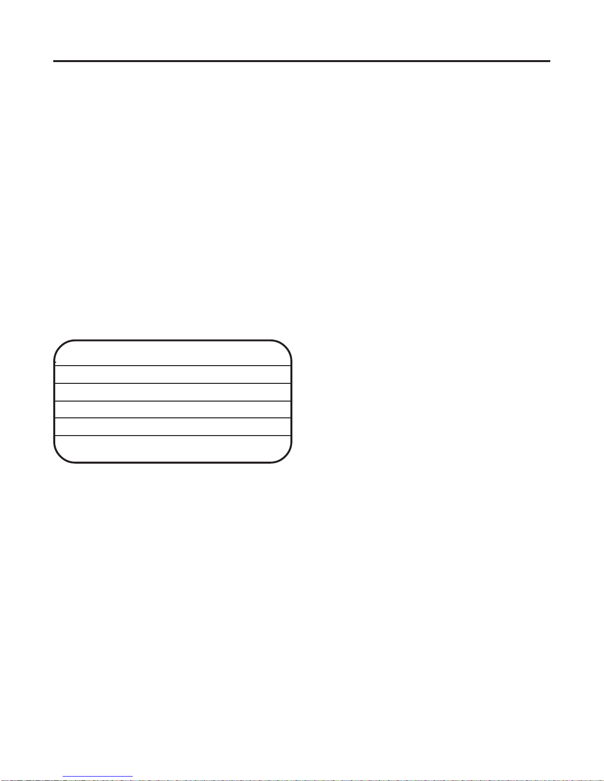
BASEPLATE
.75 TO 1.25
ALLOWANCEFOR
GROUT
DAM
PIPESLEEVE
WASHER
WEDGESORSHIMS
LEFTINPLACE
LUG
FINISHED
GROUTING .25
TOPOFFOUNDATIONLEAVE
ROUGHCLEAN&WETDOWN
GROUT
FIGURE 2a: Anchor Bolt Installation.