®
ProSeries-M M-2 Peristaltic Metering Pump
QUICK START GUIDE
All diagrams are strictly for guideline purposes only. Always consult an expert before installing metering pump on
specialized systems. Metering pump should be serviced by qualified persons only.
Always wear protective clothing, face shield, safety glasses and gloves when working on or near your metering
pump. Additional precautions should be taken depending on solution being pumped. Refer to MSDS precautions
from your solution supplier.
Risk of chemical overdose. Be certain pump does not overdose chemical during backwash and periods of no flow in circulation
system.
!
CAUTION
Mounting Hole Spacings
(for standard and extended type brackets)
M-2 Series
7.75” (19.7 cm)
2.5” (6.35 cm)
Maximum bolt hole size
0.200” diameter (4 places)
Risk of electric shock – cord connected models are supplied with a grounding conductor and grounding-type attachment plug. To
reduce risk of electric shock, be certain that it is connected only to a properly grounded, grounding-type receptacle.
!
CAUTION
!
CAUTION
WARNING
Electrical connections and grounding (earthing) must conform to local wiring codes. Be certain that a grounding conductor is
connected to terminal T11-1 located in the wiring compartment.
WARNING
Risk of electric shock - Disconnect electricity before removing the wiring compartment cover.
WARNING
Maximum working pressure (excluding pump tubes):
125 psig (8.6 bar)
Note: see individual pump tube assembly maximum pressure ratings.
Maximum Fluid temperature (excluding pump tubes):
o o
3/8” OD x 1/4” ID tubing connections: 130 F (54 C)
o o
M/NPT connections: 185 F (85 C)
Note: see individual pump tube assembly maximum temperature ratings.
Ambient Operating Temperature
O O O O
14 F to 115 F (-10 C to 46 C)
Ambient Storage Temperature
O O O O
-40 F to 158 F (-40 C to 70 C)
Operating Voltage:
115VAC/60Hz, 1ph (1.5 Amp Maximum)
230VAC/60Hz, 1ph (0.7 Amp Maximum)
220VAC/50Hz, 1ph (1.0 Amp Maximum)
240VAC/50Hz, 1ph (1.0 Amp Maximum)
Mounting Location
[Choose an area located near the chemical supply tank, chemical injection point, and electrical supply. Install the
pump where it can be easily serviced.
[Mounting brackets are included. Mount the pump to a secure surface using the enclosed mounting hardware.
[Mount the pump close to the injection point. Keep the inlet (suction) and outlet (discharge) pipe or tubing as short as
possible. Longer discharge tubing increases back pressure at pump head.
[Keep the suction lift height as low as possible. Increased suction lift heights can decrease the pump’s efficiency.
[A back flow prevention check valve is recommended at the injection point to prevent system fluid from flowing back
through the pump during tube replacement or if the tube should rupture. The check valve internals must be kept
clean. Any build up in the valve will increase the pressure at the pump reducing the life of the pump tube. Back
flow check valves are available from the factory.
[The Flex-Pro does not require back pressure. Pressure regulator valves should NOT be used as back-flow preven-
tion valves unless adjusted to the minimum possible opening pressure. Any additional pressure at the pump will
reduce the life of the pump tube.
[A pressure relief valve is recommended at the discharge of the pump to prevent excessive pressure resulting in
premature wear and damage to the pump tube in the event the discharge line becomes blocked.
FLEX-PRO
Peristaltic Metering Pump
®
Flex-Pro QUICK START GUIDE
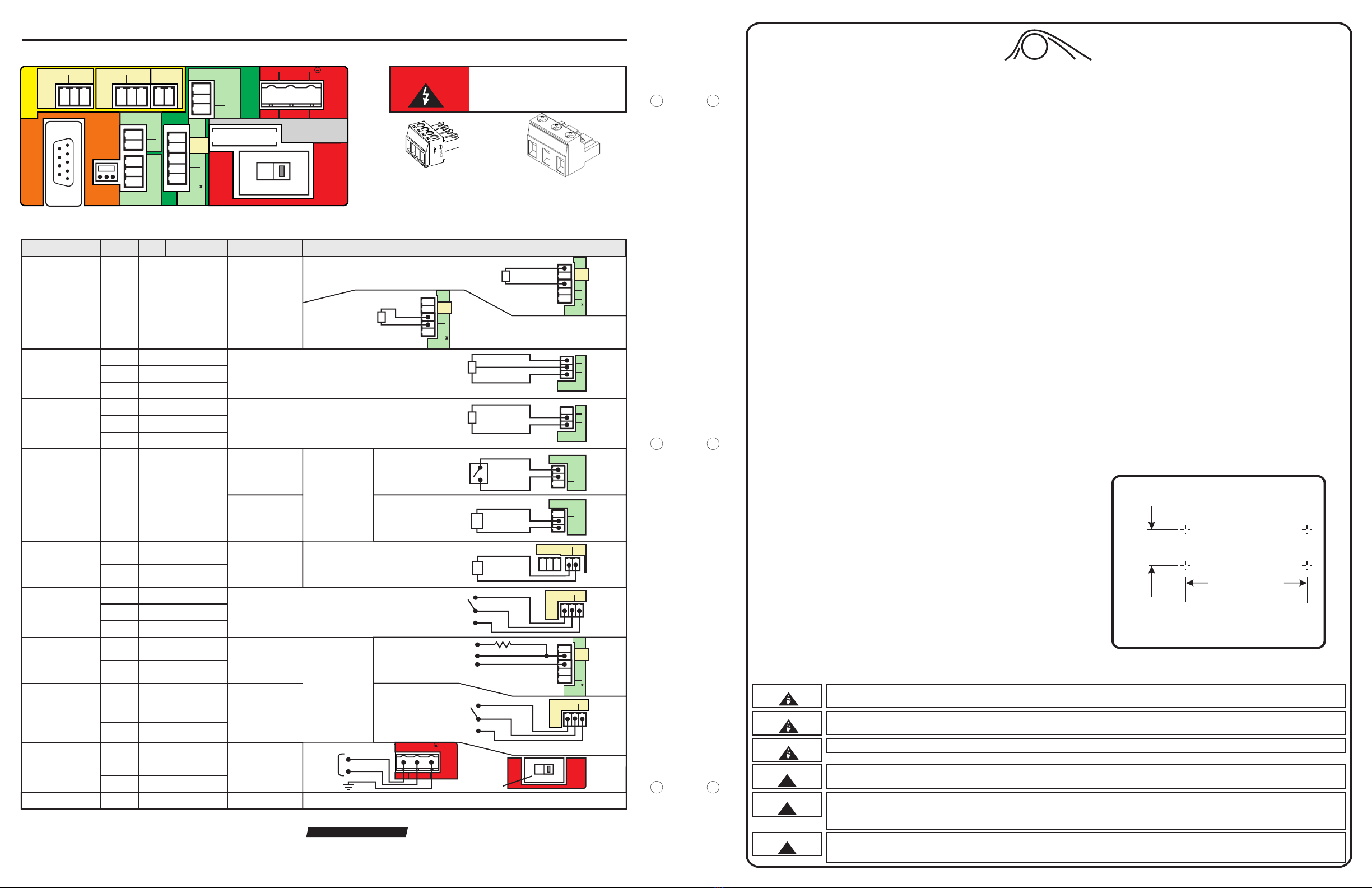
Wiring Terminals and I/O Schematics
5300 Business Drive, Huntington Beach, CA 92649 USA
Phone: 714-893-8529 FAX: 714-894-9492
ProSeries-M
by Blue-White Ind.
®
WARNING
T1
1
3
PLS
4
4-20 (+)
2
Motor
Active
(-)
5
+
-
ACTIVE 4-20mA
TRANSMITTER
SOURCE GND (-)
4-20(+)
INPUT:
4-20 mA
INPUT:
FREQUENCY, AC
SINE WAVE, TTL,
CMOS
FUNCTION TERM PIN # RATING ELECTRICAL SP. BLOCK DIAGRAM
T1
T1
T1
T1
T4
T4
T4
1
3
3
4
3
4
5
(+) POSITIVE
SIGNAL
(-) NEGATIVE
OUTPUT:
4-20 mA
OUTPUT:
RELAY, 3 AMP
OUTPUT:
OPEN COLLECTOR
MOTOR ACTIVE
T6
T6
2
1
(+) POSITIVE
(-) NEGATIVE
T7 1
T7
T7
2
3
120 OHM
IMPEDANCE, NON
POWERED LOOP
6 TO 30 VOLT DC
1 AMP MAX.
120 OHM
RESISTANCE
ACTIVE LOOP
Form C
3 AMP MAX AT
250 VAC,
3 AMP MAX AT
30 VOLT DC
0-1000 HZ MAX.
NO VOLTAGE
(+)
(-)
NO
C
NC
SWITCH LOAD
3 AMP MAX @ 250V AC
3 AMP MAX @ 30V DC
EXTERNAL DEVICE
6 TO 30V DC
OPEN CIRCUIT
IMPEDANCE MUST
BE GREATER THAN
50K OHM
4-20mA RECEIVER
600 OHM LOAD MAX.
(+)
(-)
Risk of electric shock - All
wiring must be insulated
and rated 300V minimum.
Terminals T1 Thru T8
Plug type
16 - 24 AWG
Power Input Terminal T11
Plug type
14 - 30 AWG
Single or dual pump (series) input.
Loop voltage must not exceed 24 Volts.
T1
1
3
PLS
4
4-20 (+)
2
Motor
Active
(-)
5
+
-
FREQUENCY
TRANSMITTER
SOURCE
GND (-)
PULSE
T4 FVS
3
4
5
(+)
(-) SIG
BLUE-WHITE
FVS SENSOR
GND (-)
SIGNAL
PWR (+)
RED (+)
BLACK (-)
BARE
T3 REMOTE
IN
3
1
2
DRY
RMT
COM
T3
T3
1
2
(+) POSITIVE
(-) NEGATIVE
T3
T3
2
3
(+) POSITIVE
(-) NEGATIVE
T3 REMOTE
IN
3
1
2
DRY
RMT
COM
T4
T4
4
5
SIGNAL
(-) NEGATIVE
T4 FVS
3
4
5
(+)
(-) SIG
BLUE-WHITE
MICRO-FLO
FLOWMETER
PULSE OUTPUT
GND (-)
SIGNAL
PWR (+)
NEGATIVE (-)
SIGNAL
12
(-) (+)
T6
T7
RELAY
OUT
123
N.C. COM N.O.
(-)
(+)
T1
1
3
PLS
4
4-20 (+)
2
Motor
Active
(-)
5
GND (-)
T1
T1
2
3
CLOSED WHILE
MOTOR IS
ENERGIZED
NEGATIVE (-)
SIGNAL OUT
4.7K OHM MOTOR
ACTIVE
5 TO 24 VDC
INPUT:
POWER T11 1
T11
T11
2
3
T11
GROUND
N EUTRAL
(COMMON)
LINE
(HOT)
1
23
POWER
AC
VOLTAGE
115V OR 230V AC
MANUAL SWITCH
50 / 60 HZ
100W
GROUND
NEUTRAL
LINE (HOT)
115V
POWER
S1
POWER
VOLTAGE
SWITCH
SWITCH
FROM
115V TO 230V
FUSE F1 N/A 5 AMP 5A SLOW BLOW
(20 X 5MM)
(+) POSITIVE
(-) NEGATIVE
(-) NEGATIVE
(+) POSITIVE
INPUT:
FVS SYSTEM
(FLOW VERIFICATION
SENSOR)
FS or FP MICRO-FLO
FLOW METER ONLY
INPUT:
FVS SYSTEM
(FLOW VERIFICATION
SENSOR)
FV SENSOR ONLY
INPUT:
REMOTE
START / STOP
(DRY CONTACT C.)
INPUT:
REMOTE
START / STOP
(WET CONTACT C.)
NORM. CLOSED
NORM. OPEN
COMMON
4-20
COMMON
SIGNAL
NOTE: USE
ONLY DRY
CONTACT FOR
REMOTE S/S
WHEN USING
4-20mA INPUT
Shielded cables should be used on all input signal wires.
OUTPUT:
MOTOR ACTIVE
(CONTACT CLOSURE)
Form C
1 AMP MAX AT
125 VAC,
0.8 AMP MAX AT
30 VOLT DC
T8 1
T8
T8
2
3
NORM. CLOSED
NORM. OPEN
COMMON
T8
MOTOR
ACTIVE
123
N.C. COM N.O.
T8
MOTOR
ACTIVE
123
N.C. COM N.O.
NO
C
NC
SWITCH LOAD
1 AMP MAX @ 125V AC
0.8 AMP MAX @ 30V DC
P1
RS-232
TO COM
BOARD
T12
OUTPUT
T7
RELAY
OUT
123
N.C. COM N.O. 4-20mA
12
(-) (+)
T6
T8
MOTOR
ACTIVE
123
N.C. COM N.O.
T2
T4 FVS
1
2
(-) (+)
3
4
5
(+)
(-) SIG
DIR
115V
FUSE 5A SLOW
BLOW (20 X 5MM)
POWER
T11
GROUND
N EUTRAL
(COMMON)
LINE
(HOT)
1
23
S1
INPUT
T3 REMOTE
IN
T1
3
1
2
DRY
RMT
COM
1
3
PLS
4
4-20 (+)
POWER
F1
(-)
5
2
Motor
Active


