PACOM PPRO-C-A420-WDR-MZIR User manual
Installation Manual
2MP WDR MFZ Bullet Camera
Proudly distributed by
Visit "http://www.hills.com.au/branches" to nd your nearest Hills oce,
or contact us at 1800 685 487 for more information.

2
This is a basic installation manual for use of a network camera. Users who are using this product for the rst time, as
well as users with experience using comparable products, must read this manual carefully before use and heed to the
warnings and precautions contained herein while using the product. Safety warnings and precautions contained in
this manual are intended to promote proper use of the product and thereby prevent accidents and property damage
and must be followed at all times. Once you have read this manual, keep it at an easily accessible location for future
reference.
•The manufacturer will not be held responsible for any product damage resulting from the use of unauthorized parts and
accessories or from the user's failure to comply with the instructions contained in this manual.
•The information in this document is believed to be accurate as of the date of publication even though explanation
about some functions may not be incorporated. The manufacturer is not responsible for any problems resulting from
the use thereof. The information contained herein is subject to change without notice. Revisions or new editions to this
publication may be issued to incorporate such changes.
•It is recommended that rst-time users of this network camera and individuals who are not familiar with its use seek
technical assistance from their retailer regarding product installation and use.
•If you need to disassemble the product for functionality expansion or repair purposes, you must contact your retailer and
seek professional assistance.
•Both retailers and users should be aware that this product has been certied as being electromagnetically compatible for
commercial use. If you have sold or purchased this product unintentionally, please replace with a consumer version.
Safety Symbols
Symbol Publication Description
IEC60417, No.5031 Direct current
IEC60417, No.5032 Alternating current
In-Text
Symbol Type Description
Caution Important information concerning a specic function.
Note Useful information concerning a specic function.
Before reading this manual

Before reading this manual
3
Safety Precautions
WARNING
RISK OF ELECTRIC SHOCK
DO NOT OPEN
WARNING: TO REDUCE THE RISK OF ELECTRIC SHOCK,
DO NOT REMOVE COVER (OR BACK).
NO USER-SERVICEABLE PARTS INSIDE.
REFER SERVICING TO QUALIFIED SERVICE PERSONNEL.
Important Safeguards
1. Read Instructions
All the safety and operating instructions should be read before the
appliance is operated.
2. Retain Instructions
The safety and operating instructions should be retained for future
reference.
3. Cleaning
Unplug this equipment from the wall outlet before cleaning it. Do not
use liquid aerosol cleaners. Use a damp soft cloth for cleaning.
4. Attachments
Never add any attachments and/or equipment without the approval
of the manufacturer as such additions may result in the risk of re,
electric shock or other personal injury.
5. Water and/or Moisture
Do not use this equipment near water or in contact with water.
6. Placing and Accessories
Do not place this equipment on an wall or ceiling
that is not strong enough to sustain the camera. The
equipment may fall, causing serious injury to a child
or adult, and serious damage to the equipment. Wall
or shelf mounting should follow the manufacturer's
instructions, and should use a mounting kit approved
by the manufacturer.
This equipment and cart combination should be moved with care.
Quick stops, excessive force, and uneven surfaces may cause the
equipment and cart combination to overturn.
Do not place this equipment in an enclosed space. Sucient
ventilation is required to prevent an increase in ambient temperature
which can cause malfunction or the risk of re.
7. Power Sources
This equipment should be operated only from the type of power
source indicated on the marking label. If you are not sure of the
type of power, please consult your equipment dealer or local power
company.
You may want to install a UPS (Uninterruptible Power Supply)
system for safe operation in order to prevent damage caused by an
unexpected power stoppage. Any questions concerning UPS, consult
your UPS retailer.
This equipment should be remain readily operable.
8. Power Cord
Operator or installer must remove power and TNT connections before
handling the equipment.
9. Lightning
For added protection for this equipment during a lightning storm,
or when it is left unattended and unused for long periods of time,
unplug it from the wall outlet and disconnect the antenna or cable
system. This will prevent damage to the equipment due to lightning
and power-line surges. If thunder or lightning is common where the
equipment is installed, use a surge protection device.
10. Overloading
Do not overload wall outlets and extension cords as this can result in
the risk of re or electric shock.
11. Objects and Liquids
Never push objects of any kind through openings of this equipment
as they may touch dangerous voltage points or short out parts that
could result in a re or electric shock. Never spill liquid of any kind on
the equipment.
12. Servicing
Do not attempt to service this equipment yourself. Refer all servicing
to qualied service personnel.
13. Damage requiring Service
Unplug this equipment from the wall outlet and refer servicing to
qualied service personnel under the following conditions:
A. When the power-supply cord or the plug has been damaged.
B. If liquid is spilled, or objects have hit the equipment.
C. If the equipment has been exposed to rain or water.
D. If the equipment does not operate normally by following the
operating instructions, adjust only those controls that are covered
by the operating instructions as an improper adjustment of other
controls may result in damage and will often require extensive work
by a qualied technician to restore the equipment to its normal
operation.
E. If the equipment has been dropped, or the cabinet damaged.
F. When the equipment exhibits a distinct change in performance —
this indicates a need for service.
14. Replacement Parts
When replacement parts are required, be sure the service technician
has used replacement parts specied by the manufacturer or that
have the same characteristics as the original part. Unauthorized
substitutions may result in re, electric shock or other hazards.
15. Safety Check
Upon completion of any service or repairs to this equipment, ask the
service technician to perform safety checks to determine that the
equipment is in proper operating condition.
16. Field Installation
This installation should be made by a qualied service person and
should conform to all local codes.
17. Correct Batteries
Warning: Risk of explosion if battery is replaced by an incorrect type.
Replace only with the same or equivalent type.
Dispose of used batteries according to the instructions.
The battery shall not be exposed to excessive heat such as sunshine,
re or the like.
18. Tmra
A manufacturer’s maximum recommended ambient temperature
(Tmra) for the equipment must be specied so that the customer and
installer may determine a suitable maximum operating environment
for the equipment.

4
FCC Compliance Statement
THIS EQUIPMENT HAS BEEN TESTED AND FOUND TO COMPLY WITH THE LIMITS FOR A CLASS A DIGITAL DEVICE, PURSUANT TO PART
15 OF THE FCC RULES. THESE LIMITS ARE DESIGNED TO PROVIDE REASONABLE PROTECTION AGAINST HARMFUL INTERFERENCE
WHEN THE EQUIPMENT IS OPERATED IN A COMMERCIAL ENVIRONMENT. THIS EQUIPMENT GENERATES, USES, AND CAN RADIATE
RADIO FREQUENCY ENERGY AND IF NOT INSTALLED AND USED IN ACCORDANCE WITH THE INSTRUCTION MANUAL, MAY CAUSE
HARMFUL INTERFERENCE TO RADIO COMMUNICATIONS. OPERATION OF THIS EQUIPMENT IN A RESIDENTIAL AREA IS LIKELY TO
CAUSE HARMFUL INTERFERENCE, IN WHICH CASE USERS WILL BE REQUIRED TO CORRECT THE INTERFERENCE AT THEIR OWN EXPENSE.
WARNING: CHANGES OR MODIFICATIONS NOT EXPRESSLY APPROVED BY THE PARTY RESPONSIBLE FOR COMPLIANCE COULD VOID
THE USER’S AUTHORITY TO OPERATE THE EQUIPMENT. THIS CLASS OF DIGITAL APPARATUS MEETS ALL REQUIREMENTS OF THE
CANADIAN INTERFERENCE CAUSING EQUIPMENT REGULATIONS.
WEEE (Waste Electrical & Electronic Equipment)
Correct Disposal of This Product
(Applicable in the European Union and other European countries with separate collection systems)
This marking shown on the product or its literature, indicates that it should not be disposed with other household
wastes at the end of its working life. To prevent possible harm to the environment or human health from
uncontrolled waste disposal, please separate this from other types of wastes and recycle it responsibly to promote
the sustainable reuse of material resources.
Household users should contact either the retailer where they purchased this product, or their local government
oce, for details of where and how they can take this item for environmentally safe recycling.
Business users should contact their supplier and check the terms and conditions of the purchase contract. This
product should not be mixed with other commercial wastes for disposal.
Copyright
© 2016 Pacic Communications
Pacic Communications reserves all rights concerning this manual.
Use or duplication of this manual in part or whole without the prior consent of Pacic Communications is strictly
prohibited.
Contents of this manual are subject to change without prior notice for reasons such as functionality enhancements.
Registered Trademarks
Pacic Communications is a registered trademark of Pacic Communications.
Other company and product names are registered trademarks of their respective owners.
This product contains software built partially on open-source content. Codes for the corresponding open-
source content are available for download. For more information, refer to the software CD (OpenSourceGuide\
OpenSourceGuide.pdf) or the open source guide accompanying this manual.

5
Table of Contents
1
2
3
Part 1 – Introduction.........................................6
Product Features ................................................................6
Accessories. . . . . . . . . . . . . . . . . . . . . . . . . . . . . . . . . . . . . . . . . . . . . . . . . . . . . . . . . . . . . . . . . . . . . . 8
Overview .......................................................................9
Body......................................................................................9
Cable ....................................................................................10
Factory Reset ............................................................................12
Installation .....................................................................12
Installation...............................................................................12
Dimensions ..............................................................................12
Part 2 - Camera Connection .................................13
With DirectIP™ NVR-based Layout...............................................13
With non DirectIP™ NVR-based Layout ..........................................14
Part 3 - Appendix ...........................................15
Troubleshooting ...............................................................15
Specications ..................................................................16

6
Product Features
A420-WDR-MZIR is an IP-based network camera that
compress and transmit video over ethernet.
You can use the INIT program to change network
camera settings or the SiRiS Lite program to manage
multiple network cameras. In addition, the embedded
web server (WebGuard) lets you remotely view live
video using a web browser. In addition, you can use the
SiRiS Lite to manage network cameras and view/record
video.
In this manual, the term Remote System refers to the
computer on which the remote program (SiRiS Lite or
WebGuard) is running.
•Supports DirectIP mode working with a DirectIP™
NVR that allows users to simply set up all required
congurations without a PC
•Supports ONVIF protocol
(Core specication version 2.4.0)
•Multi-streaming for high-resolution and high-quality
video monitoring and simultaneous recording in real-
time as well as exible congurations for those
•Supports H.264 video compression and M-JPEG still
image compression algorithms
•Supports 4-stage video compression rate and
multiple compression resolutions
•Two-way audio communication support for remote
audio dialog
•Video stream buering to counter pre-/post-event
buering and network delays for improved network
recording reliability
•Remote monitoring via web browser or remote
software
•Automatic web casting code (HTML) generation
•Up to 10 simultaneous remote monitoring
connections
•IP ltering, HTTPS, SSL, IEEE 802.1X, and congurable
user authority levels for greater security
•Network bandwidth limitation and MAT features for
more ecient use of network bandwidth
Part 1 – Introduction

Part 1 – Introduction
7
•Easy network access via UPnP (Universal Plug and
Play) function and embedded mDNS (Multicast DNS)
protocol
•Wide dynamic range compensation (True WDR) for
improved video quality in high-contrast situations
•Slow shutter support for improved low-lighting video
capture performance
•Day & Night feature (built-in IR cut lter changer)
•Optical zoom functionality with an optical zoom lens
•Auto focus functionality
•Video out feature (selectable NTSC/PAL)
•Quick and easy rmware upgrade over the network
•Redundant rmware and auto recovery features for
improved system stability
•Network-based integrated management of multiple
network cameras
•Multiple event detection modes
•Includes a motorized focus and zoom lens
•Supports 12 VDC and PoE (Power over Ethernet)
•Built-in heater allowing operation in a sub-zero
temperature (only when using 12 VDC power)
Remote monitoring and recording via multistreaming
are available using the SiRiS Lite program. For more
information on using SiRiS Lite, refer to its operation
manual.
There is a limit to the number of users allowed to
connect remotely via the Internet at the same time.

Part 1 – Introduction
8
Accessories
Upon purchasing the product, check inside the box to make sure all the following accessories are included. External
appearances and colors of the accessories may vary depending on the model.
Network Camera Ferrite Core
Mounting Bracket Camera Sun Shield
Installation CD
(INIT/SiRiS Lite software, Operation Manuals) Quick Guide
Allen Wrench Sun Shield Screw, O Ring (1 ea.)
Screws (4 ea.)

Part 1 – Introduction
9
Overview
Product color and design may vary depending on the model.
Body
12 3
8
4 5 67
1Lens
2IR LED
3Body
4Stand
5Bottom Cover
6Mounting Bracket
7Cable
8Sun Shield Screw Hole
•Lens
Optical zoom lens is installed.
•IR LED
A sensor in the bottom middle monitors lighting
levels and activates the IR LED during low-lighting
conditions.
•Body
The cables are connected through the stand.
•Stand
Allows you to adjust the camera direction and lens’
rotation angle. Twist the setscrews counterclockwise
and move the camera to the desired direction. Once
it is set, twist the setscrews clockwise to lock it.
•Bottom Cover
Allows you to mount the camera to the wall or ceiling
using the mounting bracket provided with the camera.
•Mounting Bracket
Allows you to mount the camera to the wall or ceiling.
•Cable
Refer to the Cable.
•Sun Shield Screw Hole
Allows you to screw the sun shield to the camera.
Part 1 – Introduction
10
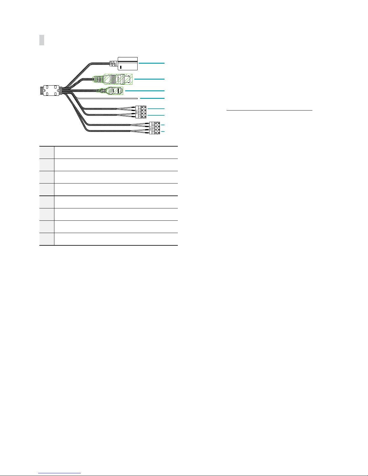
Cable
1
3
4
5
2
6
7
8
1Network Port
2BNC Video Out (Yellow Cable)
3Power In (Red Cable)
4FGND
5Audio In
6Audio Out
7Alarm In
8Alarm Out
•Network Port
Connect a network cable with an RJ-45 connector to
this port. If using a PoE switch, you can supply power
to the camera using an ethernet cable. For more
information on PoE switch use, refer to the switch
manufacturer's operation manual. You can congure,
manage, and upgrade this camera and monitor its
images from a remote computer over the network.
For more information on network connection setup,
refer to the IDIS Discovery operation manual.
•Video Out (BNC)
Connect the monitor. Use these ports for previewing
video and not monitoring video.
•Power In
Connect to the power adapter (12 VDC).
•FGND (Frame Ground)
Used to ground the device.
•Audio In
Connect an audio source to this port. (line in)
•Audio Out
Connect an amplier to this port (line out). This
device does not feature a built-in audio amplier
unit and therefore requires the user to purchase a
separate speaker system with a built-in amplier.
This manual suits for next models
1
Table of contents
Other PACOM Security Camera manuals


