Pahlen Autodos M1 User manual

Autodos M1, M2, M3
Copyright © 2015 Pahlén AB, Box 728, SE-194 27 Upplands Väsby, Sweden
Manual
User manual
Инструкция
Gerbrauchsanleitung
Manuel d’utilisation
Manuiale d’usa
Manual de instruccio-
nes
MA60-10 rev 3
2015
Art.no.
Rev.no.
Scale
Designed by: Approved by:
Revised by: Date
Drawn by: Date
Drawing number
Assembly drawing no.
Surface treatment
part of ISO 2768-1
The tolerance class in accordance with this
E
Box 728, SE-194 27 Upplands Väsby, Sweden
Phone +46 8 59411050, Fax +46 8 59086880
TS 2010-07-08
Medium
Dimensions
Autodos M1-3
M11271 0
This documentanditscontents aretheexclusive
propertyofPahlénsandmaynot becopied,
reproduced,transmittedorcommunicatedtoathird
party,orusedforanypurposewithoutwrittenpermission.
127 368,6
20
22,2594,4
5,2(4x)
639
46 46
160
80
Swedish design
and manufacture
since 1967
ENGLISH
User manual

Register
1. General information about the measuring equipment .................................................................... 3
2. Technical data ..................................................................................................................................... 4
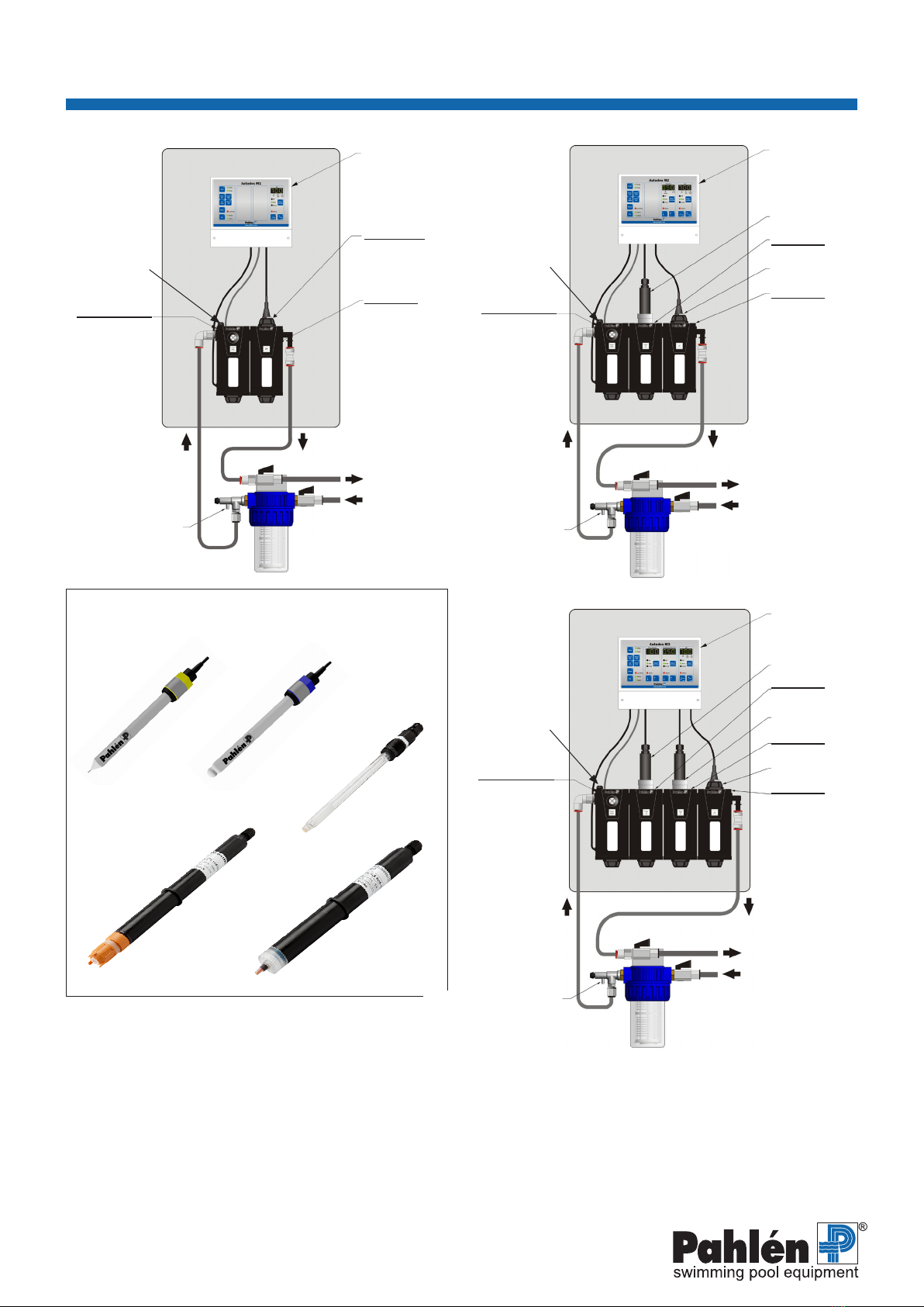
3. Model variants ..................................................................................................................................... 5
4. Program versions ............................................................................................................................... 6
5. Reservation ......................................................................................................................................... 6
6. Safety ................................................................................................................................................... 7
7. Installation ........................................................................................................................................... 7
Installation pipes ......................................................................................................................... 7
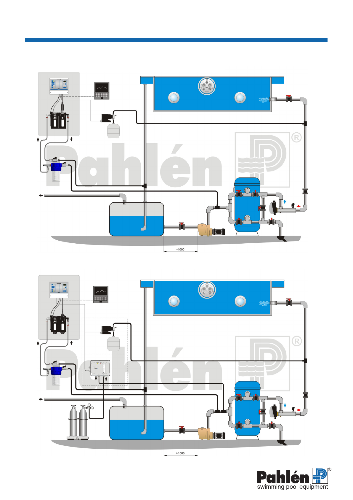
Installation example M1 ................................................................................................. 8
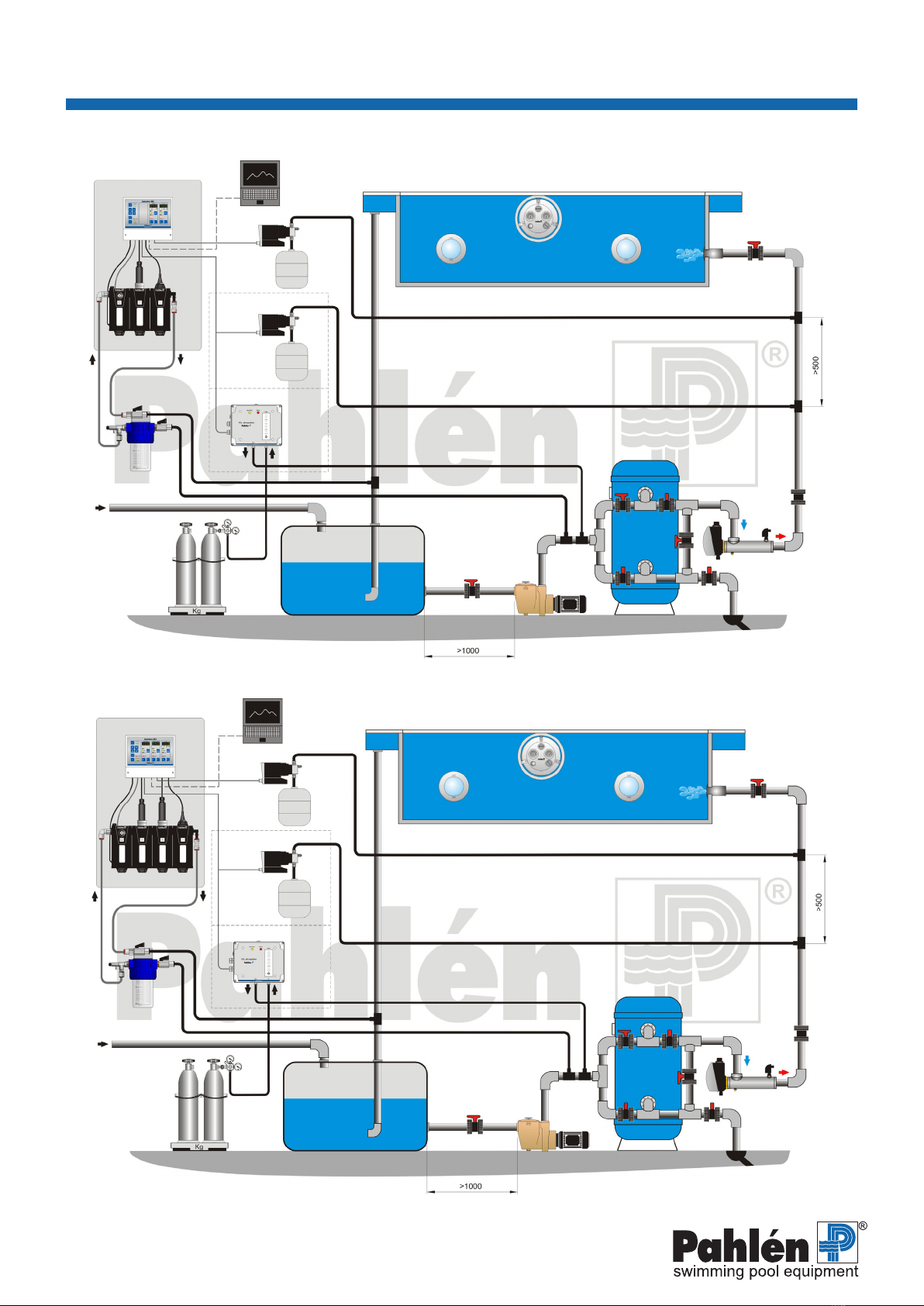
Installation example M2, M3 .......................................................................................... 9
Installation electrics ................................................................................................................... 10
Connection example M1 ................................................................................................ 10
Connection example M2, M3 ......................................................................................... 11
8. Start up guide ...................................................................................................................................... 12
9. Operation
Displays, buttons and LEDs ...................................................................................................... 13
Authorization ............................................................................................................................... 14
View/change
Set values ...................................................................................................................... 14
Alarm limits .................................................................................................................... 14
Other info: Uncalibrated values, Flow, Temp, Version, Serial no ................................... 15
Dosing selection ......................................................................................................................... 15
Other buttons: Reset, Cal, ↑ ↓ (arrow up, arrow down) ................................................................ 15
LED indicators ............................................................................................................................. 15
Text on the display, Runtime texts .............................................................................................. 16
Start-up sequence ....................................................................................................................... 16
Factory-set system conguration ............................................................................................. 17
Adjusting set values
Chlorine regulation free chlorine, (On-off/Frequency controlled) ........................................ 17
Chlorine regulation combined chlorine .......................................................................... 17
pH regulation (On-off/Frequency controlled) ....................................................................... 18
Alarm
Setting high alarm .......................................................................................................... 19
Setting low alarm ........................................................................................................... 19
Alarm diodes .................................................................................................................. 20
Alarm delay .................................................................................................................... 20
Alarm relay delay ........................................................................................................... 20
Alarm reset .................................................................................................................... 20
Showing uncalibrated values .................................................................................................... 20
System conguration ................................................................................................................. 21
Conguration of basic functions ..................................................................................... 21
Conguration - Autodos M3 Free chlorine, combined chlorine, pH .................... 22
Conguration - Autodos M3 Free chlorine, redox, pH ......................................... 23
Conguration - Autodos M2 Free chlorine/redox, pH .......................................... 24
Conguration - Autodos M1 Chlorine .................................................................. 25
Conguration - Autodos M1 Redox ..................................................................... 25
Conguration - Autodos M1 pH ........................................................................... 26
Electrode-specic conguration - general ...................................................................... 26
Conguration - Free chlorine/redox (PB200, CLE 3, Jesco, Redox) ........................ 27
Conguration - Combined chlorine (CTE 1) ......................................................... 28
Conguration - pH ............................................................................................... 29
10. Calibration
- pH ............................................................................................................................................... 30
- Redox ......................................................................................................................................... 30
- Chlorine ..................................................................................................................................... 31
- Zero point calibration ............................................................................................................... 31
- Free chlorine (PB-200 chlorine electrode) ..................................................................................... 31
- Free chlorine (Prominent 4–20mA chlorine electrode CLE 3-mA–10ppm) ......................................... 32
- Combined chlorine ................................................................................................................... 32
- Combined (totalt) chlorine (ProMinent 4–20mA chlorine electrode CTE 1-mA–10ppm) ................... 32
11. Maintenance ........................................................................................................................................ 32
12. Troubleshooting, error codes, alarm codes ..................................................................................... 32
13. Jesco free chlorine electrode (option) ............................................................................................... 34
14. Autodos PC connection (expansion) ................................................................................................. 34
15. Autodos PLC connection (expansion) ............................................................................................... 35

3
ENGLISH
Autodos M
MA60-10E
ENGLISH
Autodos M
MA60-10E
1. General information about the measuring equipment
Autodos M is an equipment intended for measurements and dosage of chemicals in swimming pools. The apparatus is equipped
with 1-3 channels (depending on model) to measure levels of chlorine (free chlorine and bound chlorine), redox and pH.
This manual covers all combinations. Please read the whole manual to get a full picture of how the system works and all its
setting possibilities.
Autodos M is delivered in two different parts: one measuring and control unit Autodos and one complete electrode kit.
• Autodos: include a measuring- and control unit, connectors, and this systems manual. The control unit is pre-
programmed with factory settings for each respective model, but individual changes are possible to make by the user.
It is also possible to enter different access codes to avoid accidental changes.
• Electrode kit: include electrodes (different electrode types depending on which measurements and results you wish to
present), calibration liquids, connectors for the electrodes, and manual for the electrodes.
Autodos M´s properties
• Measures and controls pH (base or acid dosage) and chlorine in the forms of redox, free chlorine and bound chlorine.
With regards to bound chlorine, the total level of chlorine is measured and the display shows the value for bound chlorine.
This is calculated by Total chlorine – Free chlorine = Bound chlorine.
• Autodos uses two point calibration for each measuring cannel to ensure optimal measurements.
• Has a separate galvanic part for each electrode entry point.
• Warns for uidity errors in the valve, dosage errors and measurement values outside preset boundaries.
• Continuously shows the pool water’s current pH-value, free chlorine, bound cholrine and redox in clear LED-displays.
By pressing different buttons, the displays can also be made to show other values, for example ow and temperature.
pH-regulator
pH adjustment can be used according to:
• Manuel off.
• Automatic regulation against set value as per:
a. On/off control*.
b. Pulse width control
c. Frequency control P, PD, PI or PID regulator 10–180 pulses/min.
d. Current output control P, PD, PI or PID regulator 4–20 or 0–20mA.
• Manuel dosing:
a. On/off control*: dosing relay pH always On.
b. Pulse width control: dosing relay always On.
c. Frequency control: maximum deection (10–180 pulses/min).
d. Current output control: maximum deection (20mA).
(CO2 dosing equipment requires on/off or pulse width control).
Control is programmed in conguration mode.
Acid dosing or alkali dosing On/Off is programmed in conguration mode.
Chlorine regulator
Free and combined chlorine works the same and can be used according to:
• Manuel off.
• Automatic regulation against set value:
a. On/off control*.
b. Pulse width control
c. Frequency control P, PD, PI or PID regulator 10–180 pulses/min.
d. Current output control P, PD, PI or PID regulator 4–20 or 0–20mA.
• Manuel chlorine dosing:
a. On/off control*: dosing relay chlorine always On.
b. Pulse width control: dosing relay always On.
c. Frequency control: maximum deection (10–180 pulses/min).
d. Current output control: maximum deection (20mA).
Control is programmed in conguration mode.
1–3 current outputs (free chlorine, redox, combined chlorine and pH) 0–20 mA or 4–20 mA are programmed in conguration
mode (individually for each channel). Current outputs normally follow the measurement value, but can also be congured so that
the control value is followed thereby allowing current output control.
* default from fabric

4
ENGLISH
Autodos M
MA60-10E
ENGLISH
Autodos M
MA60-10E
Separate high and low alarms (limits can be set) are indicated via ashing alarm LED(s) and a common alarm relay.
The alarm is shown as “Lo” or “Hi” on display 1–3 while the Reset button [15] is held depressed.
pH value outside of limit values stops chlorine dosing. This is indicated by a ashing AUTO LED on the chlorine channels and
the alarm text “PHF”. Chlorine dosing is stopped until the pH value has returned to a permitted value.
Flow alarm (PNP potential-free connector/turbine sensor that can be deactivated in conguration mode) is indicated via alarm
LED and alarm relay in alarm mode. The registered alarm is also shown as “FLo” on display 1–3 while the Reset button [15] is
held depressed. There is no automatic dosing during stop in ow.
All alarms have a 5-second delay, except for ow alarm, high alarm and low alarm. For the high and low alarms, delay can be
set (in Setup) between 5 and 600 seconds. The ow alarm delay can be set (in Setup) between 0 and 30 minutes.
Alarm for dosing error can be selected in conguration mode (time in minutes > 0).
Dosing error is indicated (if dosing time is selected in conguration mode) via ashing alarm LED(s) and a common alarm relay.
The alarm is shown as “doS” on display 1–3 while the Reset button [15] is held depressed.
Dosing is stopped until the alarm is reset. The dosing time counter is always zeroed with a reset.
A dosing error alarm is generated in the following conditions
• On/Off dosing, Pulse width dosing, Frequency dosing, Control output-controlled dosing :
An alarm is triggered if dosing is continual for a longer time than the specied max. time in minutes (1-60 as specied in con-
guration mode). An alarm is also triggered if manual dosing is too long.
2. Technical data
Measurement computer Autodos M1 Autodos M2 Autodos M3
Display 7 segments LED 1 x 3 digits 2 x 3 digits 3 x 3 digits
Current output 1 st 4-20 (0-20) mA 2 st 4-20 (0-20) mA 3 st 4-20 (0-20) mA
Relay outputs for dosing 1 x 1A resistive load 2 x 1A resistive load 3 x 1A resistive load
Fuses 2 x T1A 5x20mm 3 x T1A 5x20mm 4 x T1A 5x20mm
Weight 5 kg 5,3 kg 5,6 kg
Height/Width/Depth (mm) 740x410x127
Power supply 230VAC +15% -10%
Power consumption 12VA
Temperature sensor connection Screw terminal (NTC/PTC)
Flow switch input 16VDC, PNP, ca 6mA
Electrode connection pH BNC
Electrode connection redox BNC
Electrode connection, free chlorine Electrode dependent
Electrode connection, total chlorine 4–20mA current input
Standby PNP, approx. 16 VDC, approx. 5 mA
Level PNP, approx. 16 VDC, approx. 5 mA
Alarm output relay Closing/opening 1 A resistive load
Maximum load, current outputs 400 Ohm
Enclosure rating IP54
Ambient temperature 5–40 ºC
Nominal ow (min–max) 30 (20–60) l/h

5
Flow
ENGLISH
Autodos M
MA60-10E
ENGLISH
Autodos M
MA60-10E
3. Model variants
Also see point 2 page 12.
M1
M2
M3

6
M1 M2
M3
ENGLISH
Autodos M
MA60-10E
ENGLISH
Autodos M
MA60-10E
4. Program versions
Ver. 5.3: (2011-04-29)
5. Reservation
We retain the right to modify the functionality of Autodos M without prior notice. We accept no liability for any errors in this
manual or any consequences stemming from Autodos M malfunction.
We strive to keep the manual as free from errors as possible. We would therefore be grateful to have any errors or ambiguities
pointed out to us so we can correct them.
CLE 3
Free chlorine
CTE 1
Total chlorine
Redox pH
PB200
Free chlorine
Elektroder
Module 2
Start module
Flow measure-
ment
Flow switch
Water tempera-
ture
Water sample outlet
Water in
Water out
Electrode:
Redox,
Total chlorine,
pH or Free chlorine
Electronic
unit
Flow
adjustment
Module 3
pH electrode
Module 2
Free chlorine
electrode
Start module
Flow measure-
ment
Flow switch
Water tempera-
ture
Water sample outlet
Water in
Water ut
Electronic
unit
Flow
adjustment
Total chlorine
electrode
Module 3
Module 4
Module 2
pH electrode
Start module
Flow measure-
ment
Flow switch
Water tempera-
ture
Water sample outlet
Water in
Water out
Free chlorine
electrode
Electronic
unit
Flow
adjustment

7
ENGLISH
Autodos M
MA60-10E
ENGLISH
Autodos M
MA60-10E
6. Safety
To prevent direct contact between the chemicals, separate the chlorine dosing point and the acid/alkali dosing point with at least
500 mm, always ACID BEFORE CHLORINE, refering to the installation example on pages 8–9.
Lock the dosing pumps to the circulation pump using the motor guard or the ow switch.
For best results, use a photometer during calibration.
Proper installation and care is required to prevent invalidation of the warranty.
“Persons (including children) with limited physical or mental capabilities must not use the device without instructions on how to
use it in a safe manner,” as per IEC 60335-1.
7. Installation
General
The system can be installed at any time point without consideration to the life span of the electrodes as these are delivered
separately and can even be delivered at a later point in time.
Install Autodos M at a dry and vibration-free location, against rm, at support and accessible for support and reading.
The display must be well visible and the buttons easily accessible.
The ow cell should be positioned as close to the monitoring point as possible to prevent unnecessarily long response times.
Note the direction of ow.
Check that the electrode kit complies to your Autodos M unit, see point 2 page 12.
If the position of the Autodos puts it at risk of freezing, the ow cell modules must be emptied of all water and the electrodes
must be stored frost-free standing in water (save the electrode packaging for this purpose).
Note! When installing Autodos M with free chlorine electrode in pools where organic chlorine was previously used,
all water must be drained and replaced with new water.This because the cyanuric acid content in the pool water from orga-
nic chlorine (Trichlor or Dichlor) produces a signicantly higher chlorine value in a DPD no. 1 test. This makes correct calibration
impossible.
Installation, pipes
The outlet from the ow cell should be kept free from pressure, e.g. by leading outlet water to an equalization tank or a drain.
For installations in which the ow cell outlet cannot be routed without pressure to a drain or equalization tank, the measurement
water should be sampled after the lter and the return of the pump suction line.
Connections only need to be tightened by hand.
Monitoring and dosing points are most easily made with saddle clamps.
In order to prevent air from being mixed in with the measurement water (which could affect the measurement value), the
measurement connection on the pipes should not sit at the highest point.

8
ENGLISH
Autodos M
MA60-10E
ENGLISH
Autodos M
MA60-10E
Installation example 1: Autodos M1 - chlorine
PC
Autologger
Overow gutter
Inlet
Fresh water
lling Equalization
tank
Pump
Filter
Drain
Electric heater
Check
valve
Jet Swim
Lighting Lighting
Chlorine
Chlorine dosing
Prelter
Installation example 2: Autodos M1 - acid/alkali
PC
Autologger
Overow gutter
Inlet
Acid/alkali dosing
Alt. A
Alt. B CO2dosing
Acid/alkali
Scale
Fresh water
lling Equalization
tank
Pump
Filter
Drain
Electric heater
Check
valve
Jet Swim
Lighting Lighting
Prelter
Installationsexempel

9
ENGLISH
Autodos M
MA60-10E
ENGLISH
Autodos M
MA60-10E
Chlorine
dosing
Installation example 4: Autodos M3
PC
Autologger
Overow gutter
Inlet
Acid/alcali
dosing
Alt. A
Alt. B CO2
dosing
Acid/alcali
Scale
Fresh water
lling Equalization
tank
Pump
Filter
Avlopp
Electric heater
Check
valve
Jet Swim
Lighting Lighting
Chlorine
Prelter
Installation example 3: Autodos M2
PC
Autologger
Overow gutter
Inlet
Acid/alkali dosing
Alt. A
Alt. B CO2dosing
Acid/alcali
Scale
Fresh water
lling Equalization
tank
Pump
Filter
Drain
Electric heater
Check
valve
Jet Swim
Lighting Lighting
Chlorine
Chlorine
dosing
Prelter

10
Material = Polyester
Färg = Vit
Häftämne = 350
This document and its contents are the exclusive
property of Pahléns and may not be copied,
reproduced, transmitted or communicated to a third
party, or used for any purpose without written permission.
Art.no.
Rev.no.
Scale
Designed by: Approved by:
Revised by: Date
Drawn by: Date
Drawing number
Assembly drawing no.
Surface treatment
part of ISO 2768-1
The tolerance class in accordance with this
E
Box 728, SE-194 27 Upplands Väsby, Sweden
Phone +46 8 59411050, Fax +46 8 59086880
TSTS
medel
2011-01-24
T.S 2011-02-17
Etikett Autodos M1-3
Installationshål M11384
1:1
160 131 07
1
~230VAC Flow/Temp
CLE
CTE
Dosing
PB200
Redox
pH
35
180
ENGLISH
Autodos M
MA60-10E
ENGLISH
Autodos M
MA60-10E
GND free chlorine
Current input free chlorine (4–20mA)
24 VDC
Flow meter (white cable)/ – GND current outputs
Current output 1 (pH) 4–20mA (0–20mA)
Current output 2 (redox/chlorine) 4–20mA (0–20mA)
PNP in STDBY
Flow meter (green cable)/NPN in ow switch
PNP in, level switch (alarm upon closed input)
Flow meter (brown cable)/16 VDC PNP input
–GND Temperature sensor
Temperature sensor
Twin-cable communication with PC
Alarm (common)
de-energized state
230 VAC L
Acid/alkali dosing/chlorine dosing (free)
PB200 chlorine electrode
Chlorine electrode
CLE2.2
GND
V–
V+
Connection of ProMinent CLE 3-mA 10ppm
Terminal 1 (+) to terminal 26
Terminal 2 (–) to terminal 27
Accessories
Modelbus RTU
9600 band, Parity None
Example D:
Current out-
put controlled
dosing pump
Example A:
On/Off
controlled
dosing pump
Example C:
Frequency
controlled
dosing pump
Installation, electrics
Electrical installation must only be carried out by an authorized electrical installation technician.
Electrical installation must be performed after pipe installation is complete.
The equipment must be permanently grounded and monitored by a residual current device (RCD) with a maximum leakage
current of 30 mA.
The equipment should be supplied via an additional 2-pin switch.
Inputs/outputs for cables as per gure below.
View from below
The following example shows how connections are to be made
Connection example
Connection example - Autodos M1

11
230 VAC N
230 VAC L
ENGLISH
Autodos M
MA60-10E
ENGLISH
Autodos M
MA60-10E
Connection example - Autodos M2
GND free chlorine
Current input free chlorine (4–20mA)
24 VDC
Flow meter (white cable)/ – GND current outputs
Current output 1 (pH) 4–20 mA (0–20 mA)
Current output 2 (redox/chlorine) 4–20mA (0–20mA)
PNP in STDBY
Flow meter (green cable)/NPN in ow switch
PNP in, level switch (alarm upon closed input)
Flow meter (brown cable)/16 VDC PNP input
–GND temperature sensor
Temperature sensor
Twin-cable communication with PC
Alarm (common)
de-energized state
230 VAC L
Chlorine dosing (free)
230 VAC L
Acid/alkali dosing
PB200 chlorine electrode
Chlorine electrode
CLE2.2
GND
V–
V+
Connection of ProMinent CLE 3-mA 10ppm
Terminal 1 (+) to terminal 26
Terminal 2 (–) to terminal 27
Accessories
Modelbus RTU
9600 band, Parity None
Example D:
Current
output
controlled
dosing pump
Example A:
On/Off
controlled
dosing pump
Example C:
Frequency
controlled
dosing pump
Connection example - Autodos M3
GND combined chlorine
Current input combined chlorine (4–20mA)
24 VDC
GND free chlorine
Current input free chlorine (4–20mA)
24 VDC
Flow meter (white cable)/ – GND current outputs
Current output 1 (pH) 4–20mA (0–20mA)
Current output 2 (combined chlorine) 4–20mA (0–20mA)
Current output 3 (free chlorine) 4–20mA (0–20mA)
PNP in STDBY
Flow meter (green cable)/NPN in ow switch
PNP in, level switch (alarm upon closed input)
Flow meter (brown cable)/16 VDC PNP input
–GND temperature sensor
Temperature sensor
Twin-cable communication with PC
Alarm (common)
de-energized state
230 VAC L
Chlorine dosing (free)
230 VAC L, Chlorine
dosing (combined)
230 VAC L
Acid/alkali dosing
PB200 chlorine
electrode
Chlorine electrode CLE2.2
GND
V–
V+
Connection of ProMinent CTE 1-mA 10ppm
Terminal 1 (+) to terminal 29
Terminal 2 (–) to terminal 30
Connection of ProMinent CLE 3-mA 10ppm
Terminal 1 (+) to terminal 26
Terminal 2 (–) to terminal 27
Accessories
Modelbus RTU
9600 band, Parity None
Example D:
Current
output
controlled
dosing pump
Example A:
On/Off
controlled
dosing pump
Example C:
Frequency
controlled
dosing pump
230 VAC L
Acid dosing
230 VAC L
Alkali dosing
230 VAC L
Chlorine dosing (free)
Alarm (common)
de-energized state
M3 - free chlorine, redox, pH M3 -
free chlorine, combined chlorine, pH

12
ENGLISH
Autodos M
MA60-10E
ENGLISH
Autodos M
MA60-10E
8. Startup guide
This is a short check list with the different steps needed to get started with Autodos. References are given to the sections in the
manual relevant for each step. Still, read through the whole manual to have a complete picture of how the system works and all
its setting possibilities.
1. Install the Autodos unit, see section 7 Installation pipes.
2. Check that you have the correct electrode kit for your valve, see below.
Autodos Elektrodkit
M1
416500 - Free chlorine 416501 - PB200 Free chlorine
416500 - Free chlorine 416502 - CLE3 10ppm Free chlorine
416510 - pH 416511 - pH
416520 - Redox 416521 - Redox
416530 - Total chlorine 416531 - CTE1 Total chlorine
M2
416540 - Free chlorine , pH 416541 - PB200 Free chlorine & pH
416540 - Free chlorine , pH 416542 - CLE3 10ppm Free chlorine & pH
416540 - Free chlorine , pH 416543 - CLE3 20ppm Free chlorine & pH
416550 - Redox, pH 416551 - Redox pH
M3
416560 - Free chlorine , Redox, pH 416561 - Free chlorine PB200, Redox & pH
416560 - Free chlorine , Redox, pH 416562 - Free chlorine CLE3 10ppm, Redox & pH
416570 - Free chlorine , Combined chlorine, pH 416571 - Free chlorine , Combined chlorine, pH
3. Install the electrodes and the installation kit with connector details in the corresponding measuring cell in the valve, see
page 6. An instruction showing how the details of the installation kit shall be connected is included in each respective kit.
NOTE! The electrodes can not be dry or be exposed to frost or quick temperature changes. For more information about the
electrodes, please see the instruction “Handling and care of electrodes” which is enclosed with the electrode kit.
4. Connect the electrode connectors for the water ow for measurements and check that water ows through the valve.
5. Open the faucets for the water ow for measurements and check that water ows through the valve.
6. Turn on the voltage to Autodos M. After a startup time of 60 seconds, the values are shown in each respective channel/dis-
play, see section 9: Operation, page 13.
7. Basic settings, electrodes.
Autodos M has preset factory settings for all types of electrodes that normally corresponds to the electrode combination in
the supplied electrode kit. To check/change electrode type, see further under Systems conguration, pages 21-26.
8. Basic settings, dosage type.
Autodos M can control the dosage equipment either via on/off- frequency- , pulse width- or current control. Which to choose
depends on what dosage product that shall be connected. To check or change dosage type, see further for the specic mod-
els under Electrode specic conguration, pages 26-29.
9. Adjust the ow of water for measurement to 30-40 liters/hour with the adjustment screw on the start module. Press the
button ↑ Flow [9] and keep pushing and the current ow is shown in the right display.
10. Calibrate electrodes, see section 10: Calibration, pages 30-32.
11. Let Autodos M run without dosage for around one hour with correct ow of water after the calibration have been done. This is
because the electrodes need to adjust to the measuring water in order for the signals to be stable. Read more under section
9: Handling/choice of dosage, page 15. Normal operating mode: diode “Auto” is lit.
12. Dosage times and response times depends solely on pool volume, turnaround ratio, dosage type, and dosage ratio.
Concentrations of chemicals and dosage products also affects. See section 9: Handling/Settings recommended values,
pages 17-18.
13. Alarm; diodes with ashing lights show active or retset alarms. Pushing the button Reset [15] will shows the type of alarm.
Diodes with a steady red light are acknowledged/active alarms, see section 9: Handling/Alarm diodes, page 20.
If diode “Auto” ashes on the chlorine/redox channel, the pH-value is outside the alarm limits and no dosage is done until
the pH-value is restored within given limits.
14. Maintenance and care; see section 11: Care, page 32. All reference measurements of water quality shall be done with a
digital photometric measuring tool. The measuring water shall always be taken from the draining faucet on Autodos M´s
prelter unit.

13
ENGLISH
Autodos M
MA60-10E
ENGLISH
Autodos M
MA60-10E
9. Operation
Displays, buttons and LEDS – general
The panel is divided into 4 groups. Group 1 (on the left) handles all activities and the others show values and handle limit and
value settings.
Button
no.. Function Group
0 Calibration 1
1 Function selection 2
2 Level – 2
3 Level + 2
4 Function selection 3
5 Level – 3
6 Level + 3
7 Function selection 4
8 Level + / Temp 4
9 Level – / Flow 4
10 Authorization 1
11–14 Activity 1
15 Reset 1
The picture shows one example of all Autodos variants.
Group 1 Group 2 Group 3 Group 4
Displays
Depending on the Autodos M model variant, the values of free chlorine, combined chlorine and/or redox and pH are indecated in
one, two or three separate displays (each with three digits).
The displays can also show simple text messages; see the chapter Text display on page 16.
In some displays different values can be shown in the same eld but then requires certain keystrokes, see page 14.
Under he actual display arrows and explanatory text are found. The position of the decimal point in the display conrms which
type of value is indicated.
The display to the far right can also be used to show ow and temperature.
The displays displays parameters within the following limits:
Free chlorine: –.99–9.99 mg/l (ppm)
Combined chlorine: –.99–9.99 mg/l (ppm)
pH: 4.00–11.0
Redox –99.–999. mV
Temperature: 10 – 40°C
Buttons
Each button has a unique number in the top right-hand corner. In this manual, reference is made to this number with [ ] and the
buttons text reference with bold style e.g. Reset [15].
Further on in this chapter we describe how and what buttons to press in which modes.
LEDs
Function activation is indicated with a green LED and all types of alarms are indicated with a red LED.
Read more about each LED indication on page 15.

14
ENGLISH
Autodos M
MA60-10E
ENGLISH
Autodos M
MA60-10E
Authorization
To avoid unintentional changes to settings and unauthorized use, two authorization codes can be set, see below.
NOTE! Autodos M has no authorization code set when delivered. When necessary this must be activated.
Authorization Explanation
Normal mode No settings can be altered; only Reset is possible
Authorization code 1 Set values, alarm limits and control parameters can be changed. Calibration is also possible.
Authorization code 2 All available changes, including system conguration, are possible.
Activate authorization
If no codes are set, authorization level 2 is accessed automatically when the Code button [10] is pressed. The display then
shows “Cd2”.If authorization code is required “Cd–” is showing.
When the Code button [10] is held depressed, the opening code can be entered using the buttons indicated below:
Autodos M3: Buttons 0–9
Autodos M2: Buttons 0 and 4–9
Autodos M1: Buttons 0 and 7–9
If the entered code is the same as opening code 1 you access authorization level 1 and if the entered code is the same as open-
ing code 2 you access authorization level 2 when the Code button [10] is released. This is indicated via the “Code” LED being
illuminated for authorization level 1 and ashing for authorization level 2..
Set/select authorization code
The opening code can only be changed in authorization level 2. If you forgot the code for authorization level 2, it can be dis-
played by pressing Code [10] during the start-up sequence (after the countdown of seconds has begun).
Enter the opening code (for authorization level 1 or level 2):
1. Access authorization level 2.with the button Code [10], diode “Code” ashes.
2. Enter calibration mode, with the button Cal [0], diode “Active” light steadily.
3. Hold the button Code [10] depressed and enter the opening code with buttons [0] – [9]. Reset [15] is used to clear the display
and enter up to six digits for the code. The display shows “Cd1” when the button Code [10] is pressed the rst time. “Cd2” is
shown the next time the button is pressed. The display then switches back and forth each time the button is pressed. The text
indicates which code (for authorization level 1 or 2) should be entered.
View/change set values
M3
Press and hold the button Set value [13] (or the button Set alk/Cl [13]) to display the set value
- for free chlorine on display 1
- for combined chlorine/redox on display 2
- for pH on display 3
To change the set value, hold the button [13] depressed while pressing ↑ or ↓ under the relevant display.
M2
Press and hold the button Set value [13] to display the set value
- for chlorine/redox on display 1
- for pH on display 2
To change the set value, hold the button depressed while pressing ↑ or ↓ under the relevant display.
M1
Press and hold the button Set value [13] to display the set value.
To change the set value, hold the button depressed while pressing ↑ [9] or ↓ [8].
View/change alarm limits
HIGH
ALARM
Press and hold the button Alarm high [12] to display the high alarm limit value on the relevant display.
To change the limit value, hold the button depressed while pressing ↑ or ↓ under the relevant display.
At least authorization level 1 is required in order to make changes.
LOW
ALARM
Press and hold the button Alarm low [14] to display the low alarm limit value on the relevant display.
To change the limit value, hold the button depressed while pressing ↑ or ↓ under the relevant display.
At least authorization level 1 is required in order to make changes.

15
ENGLISH
Autodos M
MA60-10E
ENGLISH
Autodos M
MA60-10E
Showing other information on the display
Show
Uncalibrated
values
Press and hold the Set value [13] (or Set Alk/Cl [13]) and Alarm low [14] buttons simultaneously to show
uncalibrated values on the relevant display.
Show
Flow Press and hold the ↑ Flow button [9] to display ow in litres per hour.
Show
Temperature Press and hold the ↓ Temp button [8] to display temperature (in °C).
Show
Version
Press and hold the Alarm high [12] and Alarm low [14] buttons simultaneously to display the program
version.
Show
Serial number
Press and hold the Function [11] (or Set Acid [11]) and Alarm high [12] buttons simultaneously to display
the factory-programmed serial number.
Dosing selection
Select
Function
Press the Select function button [1], [4] or [7] to switch dosing selection between Off and Auto.
Dosing can be deselected in conguration mode.
To access manual dosing: press and hold the Select function button depressed, then press Set value [13]
button also. (The Set value button [13] is called Set alk/Cl [13] on M3 with redox.)
Deactivate manual dosing by pressing the Select function button.
Off No dosing
Auto Automatic dosing based on set parameters (normal setting)
Dosing Indicates dosing (including when there is an error; stopped if there is a dosing time error)
Other buttons
Reset
Press and hold the Reset button [15] to display triggered alarms for the respective channel in the form of a
brief text. If the button is depressed for less than about one second, the alarms are reset and the common
alarm relay is de-energized. The dosing time counter is always zeroed with a reset.
Cal.
Press the Cal. button [0] to page in calibration mode between Off – Active – Adjust ...
This is indicated via unlit LEDs (Off), illuminated Active LED or illuminated Active and Adjust LEDs.
(Exit calibration mode by pressing and holding Cal. [0] until the LEDs go out.)
↑ ↓ Use the arrow buttons to adjust set values, limits and calibration values on the relevant display.
If an arrow button is held in, a “fast forward” function engages after about one second.
LEDs – dosing indicators
Off Dosing of pH-regulating or chlorine-regulating agent is deactivated.
Auto Dosing of pH-regulating or chlorine-regulating agent is regulated automatically.
Dosing Dosing of pH-regulating or chlorine-regulating agent is in progress.
If neither LED “Off” nor “Auto” is illuminated, then manual dosing is selected. If dosing does not occur at this time (the LED
“Dosing” is not lit), then dosing was deselected at setup. It may also be deactivated due to excessively long dosing time if this
function has been selected. If this is the case the “Alarm” LED will ash also (or be illuminated).
If the pH value is outside of alarm limits, there is an alarm on the chlorine channel if chlorine dosing is active.
Chlorine dosing is stopped until the pH values are once again within permitted limits.
The alarm is indicated via a ashing “Auto” LED on the chlorine channel and the alarm test “PHF” at Reset..
LEDs – alarm indicators
Low ow Insufcient ow in the ow cell.
Alarm High alarm, low alarm, dosing error or ow error.
If the “Alarm” LED ashes, there is an error that has not been cleared. If an error has been cleared but remains active, the LED
is illuminated with a steady glow.

16
ENGLISH
Autodos M
MA60-10E
ENGLISH
Autodos M
MA60-10E
LEDs – indicators for calibration in progress
Active Calibration in progress; calibration of pH7, pH9 and chlorine zero points possible.
Adjust Calibration in progress; calibration of chlorine values possible.
If the “Active” LED ashes, it indicates you are in conguration mode (see the chapter System conguration on page 21).
To exit conguration mode, press and hold the Cal. button [0] until the “Active” LED stops ashing.
LEDs – indicators for other functions
Code Indicates code mode (change of settings possible), steady = authorization level 1, ashing = authorization level 2.
Stdby Indicates input that switches off alarm and dosing; the alarm relay is activated when the input is activated.
Text on the display
Runtime texts
A list of texts that may be displayed during normal program operation and the contexts in which they occur is found below:
- - - EEP Er1 at rst start-up or EEPROM error; reset gives default setting.
dEL SEC # # # restart performed, # # # indicates the time before start delay is nished.
Error codes
See section 12: Troubleshoting, sid 32.
Start-up sequence
When Autodos M is started up, a text (see below) is shown. The three digits in the text indicate how many seconds are left until
the end of the start-up sequence. The waiting time during start-up is intended to avoid problems with alarms being triggered
because the measurement values have not had time to stabilize, etc. (The start delay can be bypassed by pressing and holding
the Reset button [15] for about one second.)
Autodos M3: ”dEL SEC 059”
Autodos M2: ”SEC 059”
Autodos M1: ”059”

17
börvärde klor
doser-område
max klor-dos (ca 100 pulser/min)
ca 30 pulser/min
ca 70 pulser/min
ärvärde klor
börvärde klor
slut klor-dosering
ärvärde klor
start klor-dosering
ENGLISH
Autodos M
MA60-10E
ENGLISH
Autodos M
MA60-10E
Factory-set system conguration:
Inställning Free chlorine Combined chlorine pH Redox
Set value 1.00 0.50 7.40 740
Low alarm 0.40 0.00 6.80 600
High alarm 2.00 1.00 7.80 800
Adjusting set value – General
Set values etc. that have been set are saved in EEPROM approx. 10 seconds after they are entered. The values are saved
alternatingly in two separate memory areas to avoid errors due to loss of power during the saving phase.
Adjusting set value – Chlorine regulation (free chlorine)
Set value adjustment for free chlorine regulation is carried out by pressing and holding the Set value button [13].
The selected chlorine set value is then shown in the display.
To change the set value, press and hold the button while pressing ↑ or ↓ under the display. Pressing and holding an
arrow button for about one second triggers a “fast forward” function until the button is released.
Chlorine set valuer
Chlorine actual value
Chlorine dosing start
Chlorine dosing end
Chlorine set value
Chlorine actual value
approx 30 pulses/min Max. chlorine dosing
(approx. 100 pulses/min)*
Dosing
range
approx 70 pulses/min
Frequency controlled chlorine regulation (free chlorine)
Dosing range indicates the interval within which dosing is steplessly changed (pband) between 0 pulses/min and max. number
of pulses/min. Adjustment of dosing range size is done in electrode specic conguration mode (see separate chapter).
If the actual value (in gure) is greater than the chlorine set value, there is no chlorine dosing (0 pulses/min).
If actual value = (set value - dosing range) there is full dosing (approx. 100 pulses/min). In the range between the two, dosing is
modied based on the actual value. For example, if the actual value is in the middle of the dosing range, half-dosing is carried
out (approx. 50 pulses/min).
Adjusting set value – Chlorine regulation (combined chlorine)
The procedure is the same as that for free chlorine, except that the arrows [5] and [6] under display 2 are used and regulation is
done against the measurement value for combined chlorine.
On/Off controlled chlorine regulation (free chlorine)
* Default value. Adjustable to max. 180 pulses/minute

18
börvärde bas
börvärde syra
bas-dosering
ärvärde
syra-dosering
börvärde bas
doser-område
börvärde syra
max bas-dos (ca 100 pulser/min)
ärvärde
max syra-dos
ca 30 pulser/min
ca 60 pulser/min
ENGLISH
Autodos M
MA60-10E
ENGLISH
Autodos M
MA60-10E
Acid set value
Alkali set value
Actual value pH
Acid dosing
Alkali dosing
Acid set value
Alkali set value
pH actual value
approx. 30 pulses/min Max. alkali dosing
(approx. 100 pulses/min)**
Max. acid dosing
approx. 70 pulses/min
Dosing range
Adjusting set value – pH regulation
Set value adjustment for pH regulation is carried out by pressing and holding the Set value button [13].
The selected pH set value is then shown in the display. To change the set value, hold the button depressed while pressing
↑ or ↓ under display 3. Pressing and holding an arrow button for about one second triggers a “fast forward” function until the
button is released.
The gures below show dosing with both pH-elevating (alkali) and pH-lowering (acid) agent. The principle is the same, but the
direction is reversed.
On/Off controlled pH regulation
P-band* indicates the range within which dosing is steplessly changed from 0 to maximum dosing. In the example above,
acid is dosed when the actual value (= pH value) is greater than the set value. Acid and alkali are dosed when the actual value
is less than the alkali set value.
At maximum dosing, the dosing pump gives max. frequency* strokes/minute.
Presume there is acid dosing (pH value = 7.54, acid set value = 7.40), P regulation (P-band = 0.20) and frequency dosing
(max. frequency = 50 strokes/minute). Dosing is then calculated as follows:
Does = (pH actual value – acid set value) / P-band x Max. frequency = (7.54–7.40) / 0.20 × 50 = 35 strokes/minute.
If the dose as calculated above is negative, 0 strokes/minute is dosed. If the dose is greater than 50, then 50 strokes/minute
is dosed.
Frequency controlled pH regulation
* set in “Electrode specic conguration”.
** Default value. Adjustable to max. 180 pulses/minute

19
börvärde
gränsvärde för höglarm
ärvärde
larmtidpunkt
börvärde
gränsvärde för låglarm
ärvärde
larmtidpunkt
ENGLISH
Autodos M
MA60-10E
ENGLISH
Autodos M
MA60-10E
High alarm setting is done by pressing and holding the Alarm high button [12]. The high alarm limits for free chlorine, combined
chlorine and pH are then displayed in the measurement value windows.
To change the limit, press and hold the button while pressing ↑ or ↓ for the relevant channel.
Pressing and holding an arrow button for about one second triggers a “fast forward” function until the button is released.
High alarm limits can be adjusted within the intervals:
free chlorine -.99 – 9.99 ppm
combined chlorine -.99 – 9.99 ppm
pH -.99 – 9.99
Set value
Actual value
Low alarm limit value
Alarm time point
Set value
Actual value
High alarm limit value
Alarm time point
Low alarm setting is done by pressing and holding the Alarm low button [14]. The low alarm limits for free chlorine, combined
chlorine and pH are then displayed in the measurement value windows.
To change the limit, press and hold the button while pressing ↑ or ↓ for the relevant channel.
Pressing and holding an arrow button for about one second triggers a “fast forward” function until the button is released.
Low alarm limits can be adjusted within the intervals:
free chlorine -.99 – 9.99 ppm
combined chlorine -.99 – 9.99 ppm
pH -.99 – 9.99
Setting low alarm
Setting high alarm

20
ENGLISH
Autodos M
MA60-10E
ENGLISH
Autodos M
MA60-10E
Alarm diodes
The alarm diodes indicate an alert with a ashing light. The alarm relay is an alternating contact free from electric potential.
It alternates when the diode is ashing (this means that a shut off unit indicates an alarm). Upon reset/acknowledgement of
alarm, the alarm relay alternates back but the alarm diode continues to be lit if the alarm is still active or is shut off if no alarm is
active. Indications are made for low alarms, high alarms, dosage errors and ow errors.
Dosing is affected by alarm as follows:
Flow error stops all dosing (starts when ow is correct)
Low alarm pH stops chlorine dosing (starts when value is within limits)
High alarm pH stops chlorine dosing (starts when value is within limits)
Low alarm redox / chlorine no effect on dosing
High alarm redox / chlorine no effect on dosing
Low alarm free/combined chlorine no effect on dosing
High alarm free/combined chlorine no effect on dosing
Dosing error pH stops all dosing (starts after Reset)
Dosing error free/combined chlorine stops chlorine dosing (starts after Reset)
Alarm level switch no effect on dosing
All alarms have a 5-second delay
Alarm delay
The high and low alarms have a delay of 5–600 seconds (set in electrode-specic conguration).
The ow switch alarm has a delay of 0–30 minutes (set in system conguration).
This is how the alarm delay works
• Delay time is counted up when an “alarm condition” applies.
• Delay time is counted down when an “alarm condition” does not apply.
• “Alarm” is activated (LED ashes) when delay time has reached the set delay time limit.
• “Alarm” is deactivated when the alarm is reset with the Reset button [15] and when delay time has been counted down to zero.
Alarm relay delay
The alarm relay has a delay of 0–30 minutes (set in system conguration). Function as follows:
• The delay time is counted up when there is an alarm that has not been reset and when the alarm delay time has not been
zeroed.
• The delay time is reset when it is not counted up (as per condition above).
• The alarm relay is activated when the delay time has reached the set delay time limit.
• Reset [15] deactivates the alarm relay and resets the delay time.
Alarm reset
Alarm reset is carried out by pressing and holding the Reset button [15] for about one second until the LEDs stop ashing (and
the alarm relay is de-energized).
While the Reset button [15] is held depressed, the display(s) show text indicating which alarms were active when the button was
pressed (see chapter Troubleshoting on page 32, there you nd all alarm codes and what they mean).
If several alarms are active, these are displayed at a 1-second interval.
The acknowledged, non-active alarms disappear when the button is released. Pressing the button again will display the
remaining active alarms.
Reset is not possible while Autodos M is in calibration mode.
The dosing time counter is always zeroed with a reset.
Showing uncalibrated values
Display of the factory-calibrated values (as if no calibration was carried out since delivery from the factory) can be carried out by
pressing the Function [11] and Alarm low [14] buttons simultaneously (also works during calibration).
NOTE: On Autodos M3 with acid/alkali dosing, these buttons are called Set acid [11] and Alarm low [14].
The function is a good troubleshooting aid if the electrodes are not functioning normally.
This function helps troubleshooting if the electrodes do not work as intended.
This manual suits for next models
2
Table of contents
Popular Water Filtration System manuals by other brands

Davco
Davco DIESEL PRO 243 Technical manual

Blagdon
Blagdon Midipond 20000 manual

tom logisch
tom logisch aquonic manual

Tropic Creations
Tropic Creations Glamorca Roller clean 200 instructions

Burwen laboratories
Burwen laboratories 1000 Operating and service manual

LG
LG WAW73JW2RP Owner's and operator's manual