Palfinger ILSL 30 User manual

ILSL
OWNER’S MANUAL
ECN-M0258 Rev. 1.0, Date 12-06-2013
PALFINGER Liftgates, LLC. 15939 Piuma Ave., Cerritos, CA 90703
Tel (888)-774-5844 Fax (562)-924-8318
PALFINGER Liftgates, LLC. 572 Whitehead Road, Trenton, NJ 08619
Tel (609)-587-4200 Fax (609)-587-4201
Visit our website at
www.palfinger.com
for up to date information and notifications
If you received this product with damaged or missing parts,
Please contact PALFINGER Liftgates at (888)-774-5844

Revision 1.0
1
Table of Content
Table of Figures...................................................................................................................2
1. Important Notes......................................................................................................3
1.1 Attention.....................................................................................................3
1.2 Important Notes..........................................................................................3
1.3 General Information....................................................................................4
2. Safety Information..................................................................................................6
3. Basic Parts in Detail...............................................................................................8
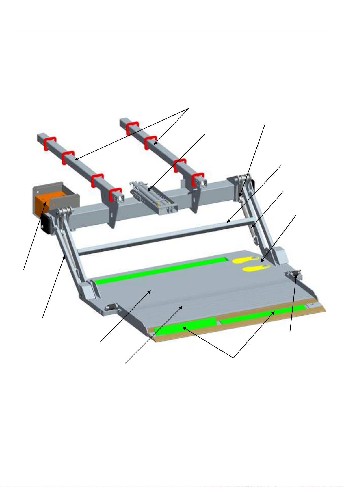
3.1 General View of Liftgate .............................................................................8
3.2 Circuit Board Connector Cables .................................................................9
3.3 Control Box...............................................................................................10
3.4 Flush mounted control (optional) ..............................................................10
4. Maximum Load and Placing of Load on Platform.............................................. 11
5. Operation of Liftgate............................................................................................12
NOTE: Never slide platform in or out with load on the platform.................12
5.1 Operating the ILSL with Control Box.........................................................12
5.2 Operating the ILSL with the 3-Button flush mounted control .....................13
5.3 Operation by Hand Held Remote Control..................................................14
5.4 Operation by Foot Control ........................................................................14
6. Preventive Maintenance and Quick Check......................................................... 15
6.1 Maintenance and Care.............................................................................15
6.2 Trailer to Tractor Connection Test............................................................16
6.3 Lubrication................................................................................................17
6.3.1 Lubrication Plan..........................................................................17
6.3.2 Checking and Changing the Oil...................................................19
6.3.3 Recommended Hydraulic Fluids .................................................19
6.4 Decal Placement and Inspection ..............................................................20
6.5 Quick Check List.......................................................................................22
7. Troubleshooting...................................................................................................23
7.1 Basic Function Check...............................................................................24
7.1.1 LIFTGATE is competely DEAD (No Clicking or Movement at all) 24
7.1.2 ON-OFF switch on, but all functions are dead.............................25
7.2 Electrical and Hydraulic Schematic...........................................................26
7.2.1 Main Wiring Diagram ..................................................................26
7.2.2 Electrical Schematics..................................................................27
7.2.2.1 Control board wiring and connector setup..................... 27

Revision 1.0
2
7.2.2.2 Control board plug setup............................................... 28
7.2.3 Hydraulic Schematic...................................................................29
7.3 Functional Description of Hydraulics when Operating...............................30
7.3.1 Slide Out Function ......................................................................30
7.3.2 Lower Down................................................................................30
7.3.3 Lift Up Function........................................................................... 30
7.3.4 Slide In Function.........................................................................30
7.4 ILSL Push-Pull Valving.............................................................................31
8. Needed Information for Ordering Spare Parts and Repairs.............................. 32
8.1 Ordering Spare Parts................................................................................32
8.2 Repairs.....................................................................................................32
9. Warranty ...............................................................................................................33
10. Contact Address ..................................................................................................34
Table of Figures
Figure 1: ILSL Slide lift ......................................................................................................8
Figure 2: Center Point of Load...............................................................................................11
Figure 3: Load Diagram (ILSL 30 and 40)..............................................................................11
Figure 4: Hand Held Remote Control with Plug & Socket Wiring........................................14
Figure 5: Lube Points18
Figure 6: Power Pack (Side View)..........................................................................................19
Figure 7: Power Pack (Top View)...........................................................................................19
Figure 8: Main Wiring ....................................................................................................26
Figure 9: Hydraulic Schematic...............................................................................................29
List of Tables
Table 1: Maintenance Schedule.............................................................................................15
Table 2: Recommended Hydraulic Fluids.............................................................................19
Table 3: Warranty Coverage Schedule..................................................................................33

Revision 1.0
3
1.
Important Notes
1.1 Attention
Before starting any operations of the liftgate, please read and understand this OWNER’S MANUAL. Its
intention is to act as a guide for the operation personal as well as to give help with preventive maintenance but
does not take place of unauthorized usage or repair by unqualified personnel.
Please contact your nearest PALFINGER Liftgates distributor or PALFINGER Liftgates in California or New
Jersey for assistance if you have questions regarding installation, operation or maintenance.
This owner’s manual applies to the following models: ILSL Slide Units 30, 40
This is the safety alert symbol. It is used to alert you to potential personal injury hazards. Obey all
safety messages that follow this symbol to avoid possible injury.
1.2 Important Notes
The PALFINGER Liftgates ILSL model is an electro-hydraulically driven lift gate, designed to be stored
underneath the truck or trailer for ultimate dock loading as well as offering up to 6-1/2 feet platform.
The Hydraulic Power Unit (HPU) is easily accessible for service and exchange. The whole assembly slides out
and can be serviced at that point. To exchange the Hydraulic Power Unit (HPU), two hoses and the battery
cables need to be disconnected.
The platform folded in half is supported by two torsion springs, each on one side, one support folding the other
unfolding operation. The platform in a stored position acts as the under ride guard. Lifting actions are carried
out by hydraulic cylinders mounted on the lift arms.
The gate is equipped with swing fixtures mounted to the bottom on each lift cylinder. This enables the platform
to lower down the tip towards the ground.
The hydraulic cylinders are equipped with solenoid operated valves located at the port of each cylinder which
prevents the platform from lowering accidently unless the operator is activating the controls. This system also
enables you to store the lift gate without a separate platform latch.
The piston rods are treated against corrosion. The HPU is equipped with a built-in pressure relief valve, which
prevents overloading when lifting.
The valves do not prevent overloading of the platform when lowering or tilting down.

Revision 1.0
4
The electric supply is taken from the vehicle battery. If the vehicle battery is not sufficient or not existing (like
on trailer units), an auxiliary battery kit needs to be installed. The electric control power is protected via a 20
Amp fuse and an on-off switch. The switch has L.E.D. lights indicating when the control power is on. (Trailer
application has an on-off switch located in the lockable control box or at the auxiliary battery box).
The liftgate is operated from an outside control box which is located on the curbside of body. Foot controls are
optional, which enables the operator to handle the cargo and operate the lift by foot. A variety of different
product options can be purchased with the PALFINGER Liftgate as well.
1.3 General Information
REMEMBER!
It is the fleet manager’s responsibility to educate the operator on the liftgate and its intended use. The
operator’s attention should be drawn to the permitted load limits and an understanding of the operation to
ensure the safety throughout the operation.
ONE-MAN OPERATION!
Never let an “outsider” operate the liftgate while you are handling the cargo.
A “misunderstanding” can result in serious personal injury.
In the interest of safety it is important that all operating personnel properly understand the functions of
the lift gate, possible hazards, dangers, the load limits and load positioning for that specific unit.
IMPORTANT NOTICE!
Before the operator uses the lift gate, they should be thoroughly familiar with the lift’s functions and
usage according to the following:
1. Improper operation of this lift can result in serious personal injury. Do not operate unless you have
been properly instructed, have read and are familiar with the operation instructions. If you do not have
a copy of the instructions please obtain them from your employer, distributor or lessor, as appropriate,
before you attempt to operate the lift.
2. Be certain the vehicle is properly and securely stopped before using the lift.
3. Always inspect this lift for maintenance or damage before using it. If there are signs of improper
maintenance, damage to vital parts or slippery platform surface, do not use the lift. Do not attempt
your own repairs unless you are specifically trained.

Revision 1.0
5
4. Do not overload. See the Rating Label on the unit for the rated load. Remember that this limit applies
to both raising and lowering operations.
5. Each load should be placed in a stable position as near as possible to the body of the truck/trailer.
6. Never stand in, move through or allow anyone else to stand in or move through the area in which the
lift operates, including that area in which a load might fall.
7. This is not a passenger lift. Do not ride the lift with unstable loads or in such a manner that a failure
would endanger you. The lift is not equipped with a back-up system to prevent falling cargo in the
event of a failure.
The maximum loads must be observed and followed!
IMPROPER USE
It is not permitted to use the tail lift:
•As an elevating work platform
•To push loads
•To carry people (Only the operator may travel on the platform)
•To clear snow
Please read through the operational and technical description of this PALFINGER Liftgate.
Thank you for choosing PALFINGER Liftgates.

Revision 1.0
6
2. Safety Information
This manual follows the Guidelines set forth in “ANSI Z535.4-2007” for alerting you to possible hazards and
their potential severity.
! DANGER indicates an imminently hazardous situation which, if not avoided, will result in death or serious
injury.
! WARNING indicates potentially hazardous situation which, if not avoided, could result in death or serious
injury.
! CAUTION indicates a potentially hazardous situation which, if not avoided, may result in minor or moderate
injury.
CAUTION without the safety alert symbol is used to address practices not related to personal injury.
(In this manual we use it to alert you to potentially hazardous situation which, if not avoided, may result in
property damage.)
NOTICE without the safety alert symbol is used to address practices not related to personal injury. (In this
manual we use it to alert you to special instructions, steps, or procedures.)

Revision 1.0
7
Improper operation of this liftgate may result in severe personal injury or death. DO NOT operate unless you
have been properly instructed, have read and are familiar with the procedures in this manual. We have
designed this manual to illustrate the steps needed for the basic operation of this ILSL liftgate. It also provides
safety information and simple preventive maintenance tips.
This manual is not intended for use as a repair or troubleshooting guide. Repairs should be performed by an
PALFINGER Liftgates Authorized Service Center.
This Manual has been designed for use in conjunction with the ILSL series liftgate only which is designed for
different capacities. You have different options to determine the type of your Liftgate:
1) Refer to the serial number tag on the Liftgate.
2) Ask your employer or lessor.
3) Call your PALFINGER Liftgates Authorized Service Center for assistance.
4) Call PALFINGER Liftgates for assistance in the USA at 888-774-5844. You can also contact PALFINGER
Liftgates by fax (562) 924-8318, or on the internet- www.PALFINGER.com
If you are facing any problems or are in need of repair, contact PALFINGER Liftgates for information regarding
experienced and trained Authorized Service Center in your area.
Replacement manuals are available, just call us & order your manuals for FREE.

Revision 1.0
8
3. Basic Parts in Detail
3.1 General View of Liftgate
Figure 1: ILSL Slide lift
Slider Rails
Push-Pull Cylinder Swing fixture
Liftarm
Lift cylinder
Foot control
Aux.
Battery kit
Parallel arm
Main section
(steel)
Tip section
(aluminum)
Cart stops
Coil springs
Folding assist

Revision 1.0
9
3.2 Circuit Board Connector Cables
No. Description Part No.
1 PC- board K plus P-2007193FP
2 Cover with hinge - for control system P-2007474
3 Clamp for cover P-2010169
4 Wire harness for control box (J30+J32) P-2007410
6 Wire harness for power pack (J1) P-2010018
7 Wire harness for circuit board power (J1+J2) P-2007406
8 Wireharness with foot control switch (J3) P-1330945
10 Cable for solenoid valve (J1), (J4), (J42.1) P-67254198
4
1
3
2
8

Revision 1.0
10
4 Hot/Power
6 down
5 up
Hot-#4.3- yellow/ green
Up-#5.2- wire 1
Down-#6.2- wire 2
Slide In-#3.2- 80 - wire4
Slide Out-# 81- wire 3
Flush Mount 3 Button Control
3 4
3 4
3 4
1 2
3 4
3 4
Hot-#4.3- yellow / green
Slide In-#3.2- 80 - wire 4
Up-#5.2- wire 1
Down-#6.2- wire 2
Slide Out-# 81- wire 3
no
no
no
nc
no
no
( Toggle-#4 )
( Toggle-#5 )
( Toggle-#6 )
Toggle Switch (Optional)
Optional
3.3 Control Box
No. Description Part No.
6 Control box with PC-board and harness P-200 9304
Control box with cable (without PC-board) P-200 7415
7 Complete outer plastic box P-200 9205
8 Operation label ATG-ILUK
9 Flip down lid P-200 7476
10 Momentary turn knob P-200 7456
11 Contact block P-200 7457
22 On- off switch P-200 9186
3.4 Flush mounted control (optional)

Revision 1.0
11
A = Distance from Truck Body to the Center
Point of Load on the Platform
A
Q
Truck or Trailer
Body
Q = Weight
Load diagram
10
20
30
40
50
60
70
80
90
100
0 12 24 36 48 60 72 84
distance from body (inch)
capacity (%)
4. Maximum Load and Placing of Load on Platform
All PALFINGER Liftgates are rated up to a maximum load. The point of maximum load is rated at a defined
distance. The center point of maximum load is at 30” for all ILSL lift gates from start of Truck or Trailer Body,
as shown in Figure 2.
Figure 2: Center Point of Load
By increasing this distance the maximum load of the lift gate is decreasing.
An overview about the rating depending, on the distance from the end of the platform is shown in the following
load diagram.
Figure 3: Load Diagram (ILSL 30 and 40)
Capacity:
100% at 30”
80% at 36”
60% at 48”
45% at 60”

Revision 1.0
12
5. Operation of Liftgate
Before use: All lift gate functions can be controlled with the 3-button control box, which is mounted on the
curb side of the truck or trailer.
NOTE: Never slide platform in or out with load on the platform.
5.1 Operating the ILSL with Control Box
1.Turn on the liftgate by rotating the ON/OFF-button
on the right hand side of the Control Box
(for different setup of on/off switch check for switch in Cab)
2. Lowering down
By rotating the bottom button clockwise/down
gate will lower out of its storage position
3. Slide out the liftgate
Rotate the top button clockwise/down to slide out the gate
completelly untill it hits the slide stops at the end of the rail.
4. Unfold the platform manually by using the straps.
5. Fold the platform for storage
Lower down the platform to about 3” off the ground.
To fold the platform, flip the tip section onto the main section.
6. Sliding in
Rotate the top button counterclockwise/up to slide
the lift gate underneath the vehicle until the gate
is in its final position and does not slide further back.
7. Raising up
By rotating the bottom button counterclockwise/up
gate will raise up into its storage position.

Revision 1.0
13
5.2 Operating the ILSL with the 3-Button flush mounted control
1. Turn on the liftgate with the on/off switch located in the cab(trucks) or at the curb side of the trailer
2. Lowering down
By pushing the bottom button the lift gate will
lower down from its storage position.
3. Slide out the liftgate
Push the two bottom buttons to slide out the gate
completely until it hits the slide stops at
the end of the rail
4. Unfold the platform
Manually by using the strap
5. Operate the liftgate
Use the top (lift) and bottom button (lower) to
operate the liftgate to load and unload the truck/trailer
6. Fold the platform for storage
Lower down the platform to about 3” off the ground.
To fold the platform, flip the tip section onto the
main section.
7. Sliding in
Push the two top buttons to slide the lift gate
underneath the vehicle until the gate is in its final
position and does not slide further back.
8. Raising up
Push the top button to raise the lift gate up
into its storage position.
SLIDE
OUT
UP
SLIDE
IN
DOWN

Revision 1.0
14
#4#5
#6
Female Receptical
(Looking at Front)
5.3 Operation by Hand Held Remote Control
Hand Controls are NOT weatherproof and are designed to be stored inside bodies in holsters or in
weatherproof boxes.
1
2
Figure 4: Hand Held Remote Control with Plug & Socket Wiring
5.4 Operation by Foot Control
DOWN:
Step on switch 1 and hold – wait between one and
three seconds before you step on switch 2.
UP:
Step on switch 2 and hold – wait between one and three
seconds before you step on switch 1.
IF BOTH SWITCHES ARE NOT ACTIVATED
WITHIN THREE SECONDS, START OVER.
1
2
Button No. 1 UP
Button no. 2 DOWN

Revision 1.0
15
6. Preventive Maintenance and Quick Check
The ILSL needs preventive maintenance to perform at its fullest capability. Lubricate and inspect regularly.
Also, check that all details are not damaged, e.g. Hoses, cables, controls, etc.
REPAIR OR REPLACE IMMEDIATELY FAULTY PARTS
6.1 Maintenance and Care
The following inspection and maintenance should be performed at the recommended intervals depending on
operation and amount of cycles or at the time when the unit shows any signs of damage or abuse. Remember
that the secret to a long life of your PALFINGER Liftgates is to maintain it through preventive care.
Recommended bases for
inspection and maintenance Depending
on use Daily Monthly Quarterly
cleaning x
general lubrication of pins and
bushings x
general lubrication of Slider Rails with
WD-40 and Push-Pull Cylinder zerks
with grease x
oil level inspection x
oil change x
check hydraulic hoses and pipes for
leaks x
check controls and connections x
check pins and pin retaining bolts x
check batteries and connections x
check warning labels and other safety
equipment for effectiveness and
visibility x
visual check for loose or missing parts
and unusual noise during operation x
check lock bolts and pins for tightness x
check complete function of gate x
check mounting brackets of lift gate to
frame for cracks or damage visually x
Table 1: Maintenance Schedule

Revision 1.0
16
6.2 Trailer to Tractor Connection Test
Testing of full systemusing a battery load tester:
Start with testing each individual battery on both tractor and trailer before proceding
to check the system:
Tractor Test:
1. Ground battery load tester on tractor chassis point (d)
Hook up positive load tester cable on positive pole of single
pole plug at end of tractor coil cord (a)
Run load test- This will test entire circuit on tractor including ground
frombatteries to tractor chassis
Trailer Test:
2. Ground battery load tester on trailer chassis (c)
Hook up positive cable on positive pole of single pole plug
recepticable on trailer (b)
Run load test - This will test entire circuit on trailer including circuit breakers &
ground between trailer batteries and trailer chassis.
Tractor and Trailer charging systemtest while connected:
3. Ground battery load tester on tractor chassis (d)
Hook up positive cable on positive pole of single pole plug
recepticable on trailer (b)
Run load test- This will test entire circuit on tractor - trailer including
ground between tractor and trailer and circuit breaker on trailer.
Asimple low amp voltage test at the front of the trailer or at the tractor
will not showinsufficient connections or ground problems
CROSSTESTON ENTIRECHARGE SYSTEM
SINGLE POLEPLUGSETUP
b
d
a 12 Volt lead from tractor coil cord
b Center (+) plug on front of trailer
cTrailer ground on front of trailer
dTractor chassis ground
cb
cb
acc

Revision 1.0
17
6.3 Lubrication
Properly lubricated, the PALFINGER Liftgates ILSL model will ensure longevity. Therefore, lubricate the lift at
the same time as the truck/trailer. Grease more frequently if the liftgate is heavily used. The liftgate should be
greased every 500 cycles (depending on use – estimated every 3 month).
Check the oil level in the tank. The level should be between the two marks 5 and 7 with platform in stored
position. Use a good quality of hydraulic fluid, ISO 32. Change oil at least once a year, preferably in the fall
before the winter is getting closer. The operation of the lift gate will accumulate condensation and some dirt
which can interfere with the lift gate functions.
6.3.1 Lubrication Plan
All bearing points must be lubricated in accordance with the maintenance intervals.
Make sure NOT to lubricate the rails with grease as it catches all dirt and mud.
Avoid this by using WD-40 for rail lubrication.

Revision 1.0
18
Figure 5: Lube Points
Location of Grease Zerks (8 on each side, 16 total)
Oil level in the power pack tank (see marking inside of power pack reservoir)
Platform hinges, Slide Rails and optional Cart Stops (use WD-40 spray for lubrication)
Oil Change on
Power Pack
4ea
3ea

Revision 1.0
19
6.3.2 Checking and Changing the Oil
Check the quality of hydraulic fluid. Take the following steps to change the oil. In stored position, lower gate to
ground (for Easy move model keep gate in stored position) and remove lock bolt. Pull the power pack out until
you can reach the oil filler cap. Unscrew the oil drainage bolt (bottom of tray) and let the fluid drain out of the
reservoir into an approved container. If the reservoir is empty fill it up with hydraulic oil, as shown on table 2.
Figure 6: Power Pack (Side View)
Figure 7: Power Pack (Top View)
6.3.3 Recommended Hydraulic Fluids
TEMP. RANGE
BRAND
-10 TO 150 F EXXON UNIVIS J26
MOBIL OIL DTE 13M
CHEVRON AW MV32
ROSEMEAD MV 150 (32)
-50 TO 150 F MOBIL DTE 13M
SHELL AERO FLUID 4
EXTREME COLD TEMPERATURE:
USE MILITARY SPEC:
MIL H5606
Table 2: Recommended Hydraulic Fluids
Hydraulic
connections
Suction filter
in oil tank
Oil filler cap
S5 Shift valve
Motor Studs
Motor Solenoid
Pressure Gauge plug Below valve block:
Oil drainage screw 6mm hexagon socket
Tray lock bolt
Oil reservoir clamp
Pressure adjustment valvePositive Stud Ground
This manual suits for next models
1
Table of contents
Other Palfinger Automatic Barrier manuals