Aprimatic PARK 30 PLUS Parts list manual

ES
DE
FR
EN
IT Istruzioni per installazione uso e manutenzione
Instructions for installation, use and maintenance
Instructions d’installation et d’entretien
Installations, Gebrauchs und Wartungsanleitungen
Instrucciones para la instalación, el uso y el mantenimiento
Barriera automatica
Automatic barrier
Barrière automatique
Automatische Schranke
Barrera automática
PARK 30 PLUS


ITALIANO ENGLISH FRANÇAIS DEUTSCH ESPAÑOL
1. Informazioni generali
1.1 Introduzione ..................................................................pag. 4
1.2 Sicurezza generale ......................................................pag. 4
1.3 Generalità .......................................................................pag. 4
1.4 Dati tecnici .....................................................................pag. 4
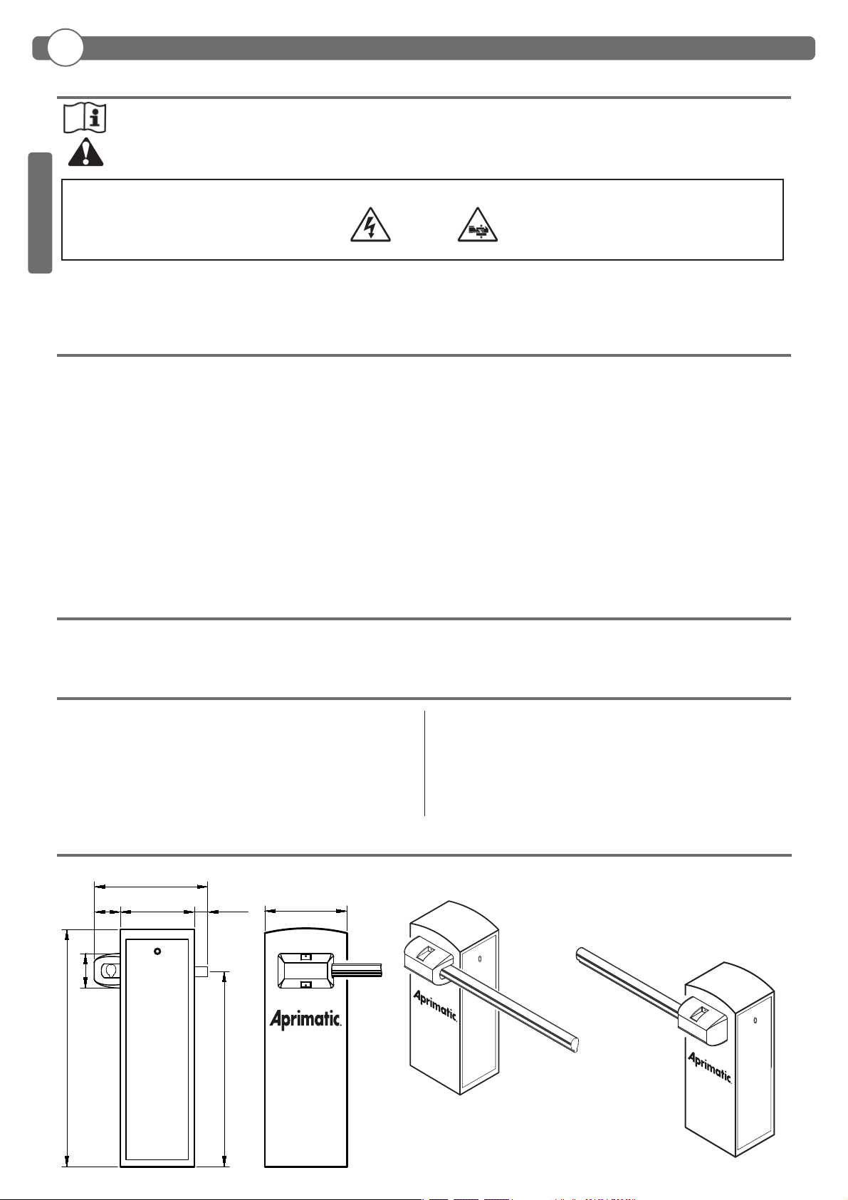
1.5 Dimensioni d’ingombro ............................................ pag. 4
2. Installazione
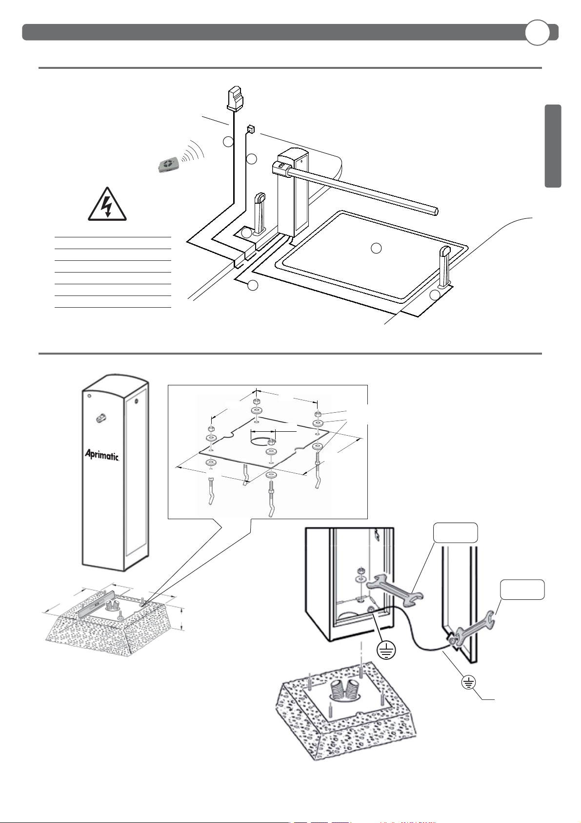
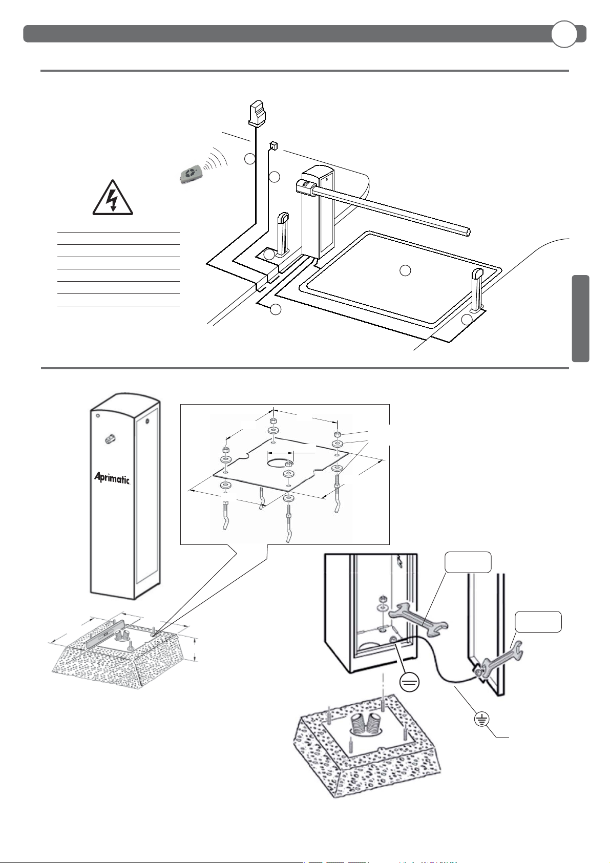
2.1 Nota cavi .........................................................................pag. 5
2.2 Fissaggio struttura ......................................................pag. 5
2.3 Installazione barra .......................................................pag. 6
2.4 Allineamento barra .....................................................pag. 6
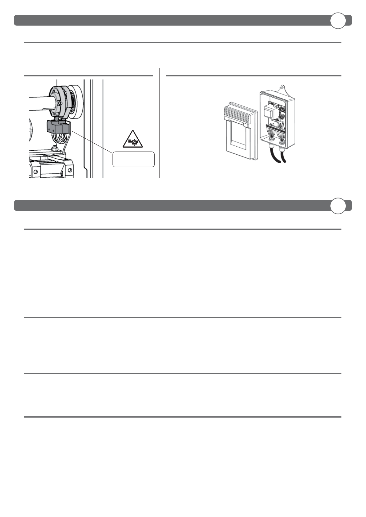
2.5 Manovra manuale .......................................................pag. 6
2.6 Equilibratura della barra ...........................................pag. 7
2.7 Optionals ........................................................................pag. 7
2.8 Collegamenti elettrici ................................................pag. 7
3. Uso e manutenzione
3.1 Sicurezza generale ......................................................pag. 7
3.2 Avvertenze .....................................................................pag. 7
3.3 Uso ....................................................................................pag. 7
3.4 Manutenzione ordinaria ...........................................pag. 7
Indice
Index
Index
Verzeichnis
Índice
1. General information
1.1 Introduction ...................................................................pag. 8
1.2 General safety ...............................................................pag. 8
1.3 General ............................................................................pag. 8
1.4 Technical speci cation ..............................................pag. 8
1.5 Overall dimensions ..................................................... pag. 8
2. Installation
2.1 Cable note ......................................................................pag. 9
2.2 Fixing the structure ....................................................pag. 9
2.3 Instal the arm ...............................................................pag. 10
2.4 Align the arm ................................................................pag. 10
2.5 Manual manoeuvre ....................................................pag. 10
2.6 Balancing the arm .......................................................pag. 11
2.7 Optionals ........................................................................pag. 11
2.8 Electrical connections ................................................ pag. 11
3. Use and maintenance
3.1 General safety ...............................................................pag. 11
3.2 Warnings .........................................................................pag. 11
3.3 Use ....................................................................................pag. 11
3.4 Routine maintenance ................................................pag. 11
1. Information generales
1.1 Avant-propos.................................................................pag. 12
1.2 Securite generale ........................................................pag. 12
1.3 Generalities ....................................................................pag. 12
1.4 Données techniques ..................................................pag. 12
1.5 Dimensions hors-tout ................................................pag. 12
2. Installations
2.1 Connexion cables ........................................................pag. 13
2.2 Fixation structure ........................................................pag. 13
2.3 Installation de la lisse ................................................pag. 14
2.4 Alignement de la lisse ...............................................pag. 14
2.5 Manoeuvre manuelle .................................................pag. 14
2.6 Equilibrage de la lisse ...............................................pag. 15
2.7 Optionals ........................................................................pag. 15
2.8 Branchements electriques .......................................pag. 15
3. Utilisation et maintenance
3.1 Sécurité générale ........................................................pag. 15
3.2 Avertissements .............................................................pag. 15
3.3 Utilisation .......................................................................pag. 15
3.4 Routine maintenance ................................................pag. 15
1. Allgemeine informationen
1.1 Einleitung .......................................................................pag. 16
1.2 Allgemeine sicherheitshinweise ............................ pag. 16
1.3 Allgemeines ...................................................................pag. 16
1.4 Technische daten ........................................................pag. 16
1.5 Abmessungen ...............................................................pag. 16
2. Installation
2.1 Bemerkung zu den kabel anschlüssen ...............pag. 17
2.2 Strukturbefestigung ...................................................pag. 17
2.3 Installation des baums .............................................. pag. 18
2.4 Die schranke ausrichten ...........................................pag. 18
2.5 Manuelles manövrieren ............................................pag. 18
2.6 Ausbilancierung des baumes .................................pag. 19
2.7 Optionals ........................................................................pag. 19
2.8 Elektrische anschlüsse ..............................................pag. 19
3. Gebrauchs und Wartungsanleitungen
3.1 Allgemeine sicherheit ................................................pag. 19
3.2 Hinweise..........................................................................pag. 19
3.3 Betrieb .............................................................................pag. 19
3.4 Ordentliche wartung ..................................................pag. 19
1. Informaciones generales
1.1 Introducción ..................................................................pag. 20
1.2 Seguridad general .......................................................pag. 20
1.3 Generalidad ...................................................................pag. 20
1.4 Datos técnicos ..............................................................pag. 20
1.5 Medidas ...........................................................................pag. 20
2. Instalación
2.1 Nota cables ....................................................................pag. 21
2.2 Fijación estructura ......................................................pag. 21
2.3 Instalación de la barra...............................................pag. 22
2.4 Alinear la barra .............................................................pag. 22
2.5 Maniobra manual ........................................................pag. 22
2.6 Equilibrado de la barra .............................................pag. 23
2.7 Optionals ........................................................................pag. 23
2.8 Conexiones eléctricas ................................................pag. 23
3. Uso y mantenimiento
3.1 Seguridad general .......................................................pag. 23
3.2 Advertencias ..................................................................pag. 23
3.3 Uso ....................................................................................pag. 23
3.4 Mantenimiento ordinario .........................................pag. 23

- 4 -
ITALIANO
1.5 DIMENSIONI D’INGOMBRO
1.1 INTRODUZIONE
Leggere attentamente il libretto prima di installare il prodotto, utilizzarlo e prima di eseguire manutenzione ordinaria o straordinaria.
Le indicazioni precedute da questo simbolo contengono informazioni di particolare importanza, il loro mancato rispetto può
comportare la perdita della garanzia contrattuale.
LE OPERAZIONI CHE EFFETTUATE IN MODO NON CORRETTO POSSONO PRESENTARE RISCHI SONO INDICATE CON I SIMBOLI:
FOLGORAZIONE SCHIACCIAMENTO
Il libretto di INSTALLAZIONE USO E MANUTENZIONE è destinato agli installatori, agli utilizzatori ed agli operatori della manutenzione.
La Ditta non è responsabile per danni arrecati a persone, animali o cose dovuti ad applicazioni che superano i limiti indicati nella scheda tecnica
allegata o dall’uso diverso da quello per cui il prodotto è stato progettato.
1.2 SICUREZZA GENERALE
• Smaltire i materiali di imballo (plastica, cartone, polistirolo, ecc.) secondo quanto previsto dalle norme vigenti. Non lasciare buste di nylon e polistirolo a
portata dei bambini.
• Non installare il prodotto in atmosfera esplosiva.
• Togliere l’alimentazione elettrica, prima di qualsiasi intervento sull’impianto. Scollegare anche eventuali batterie tampone se presenti.
• Prevedere sulla rete di alimentazione dell’automazione, un interruttore o un magnetotermico onnipolare con distanza di apertura dei contatti uguale o
superiore a 3,5 mm.
•Veri care che a monte della rete di alimentazione, vi sia un interruttore di erenziale con soglia da 0,03A.
• Applicare tutti i dispositivi di sicurezza (fotocellule, coste sensibili, ecc.) necessari a proteggere l’area da pericoli di schiacciamento, convogliamento,
cesoiamento, secondo ed in conformità alle direttive e norme tecniche applicabili.
• La Ditta declina ogni responsabilità ai ni della sicurezza e del buon funzionamento dell’automazione se vengono impiegati componenti di altri produttori.
• Usare esclusivamente parti originali per qualsiasi manutenzione o riparazione.
• Non eseguire alcuna modi ca ai componenti dell’automazione se non espressamente autorizzata dalla Ditta.
• Istruire l’utilizzatore dell’impianto per quanto riguarda i sistemi di comando applicati e l’esecuzione dell’apertura manuale in caso di emergenza.
• Non permettere a persone e bambini di sostare nell’area d’azione dell’automazione.
• Non lasciare radiocomandi o altri dispositivi di comando alla portata dei bambini onde evitare azionamenti involontari dell’automazione.
• Tutto quello che non è espressamente previsto in queste istruzioni, non è permesso.
1.3 GENERALITA’
La barriera automatica elettromeccanica è stata progettata per gestire passaggi con luce no a 3 metri nel rispetto delle normative europee. E’ la
soluzione ideale per la gestione veicolare.
1.4 DATI TECNICI
Lunghezza barra .............................................................................................................. 1,7 ÷ 3m
Temp. di esercizio ................................................................................................. -30 *** +60°C
Manovre in 24h .....................................................................................................................10 000
Grado di protezione ............................................................................................................... IP 54
Peso netto ..................................................................................................................................60 kg
Peso lordo ..................................................................................................................................62 kg
*** Con riscaldatore integrato attivo
Alimentazione ............................................................................230Vac ±10% 50/60 Hz
Motore 230Vac ........................................................................ 1.400RPM 16uF 0,27kW
Potenza assorbita...........................................................................................................300W
Centralina ...............................................................................................TRAFFIC PARK 230
Sicurezza all’urto ...................................................................................................... Reverser
Tempo di apertura .....................................................................................................................1,7s
IT
1. Informazioni generali
400
360
950
547
60
1155
168
127 Barriera DESTRA
Barriera SINISTRA

- 5 -
ITALIANO
2.1 NOTA CAVI
2.2 FISSAGGIO STRUTTURA
5
6
3
1
2
4
500
500
400
Consigliamo di rimuovere la dima
prima del ssaggio della barriera
19 mm
13 mm
Non fornito
1) Linea Monofase 2 x 1,5 + T
2) Fotocellula Trasmittente 2 x 0,5
3) Fotocellula Ricevente 4 x 0,5
4) Selettore a chiave 3 x 0,5
5) Ricevente 4 x 0,5
5) Antenna RG58
6) Spirale magnetica
M12
Ø12x35x5
200
200
250
280
Ø100
IT
2. Installazione

- 6 -
ITALIANO
2.3 INSTALLAZIONE BARRA
2.4 ALLINEAMENTO BARRA
Portabarra regolabile
• Collegare elettricamente la centralina (vedi punto 2.8)
• Dare il comando “START” per posizionare il portabarra in
posizione orizzontale
• Regolare il portabarra
PER ALLINEARE LA BARRA ALLA PAVIMENTAZIONE
STRADALE AGIRE SUL PORTABARRA REGOLABILE.
NON MODIFICARE LA POSIZIONE DEI FINECORSA
GIA’ PRETARATI
2.5 MANOVRA MANUALE
Sbloccaggio manuale
EFFETTUARE SOLO CON BARRA MONTATA
Prima di e ettuare qualsiasi intervento sull’impianto togliere l’alimentazione elettrica.
M6x65
ø6x18x2
ø12x50
Ø14
M14
Ø6x18x2
M6
M14x70
4,8x13
M8
Ø8
M8x25
Ø8
SERRARE 135Nm
IT
2. Installazione

- 7 -
FINECORSA
SUPPLEMENTARI
Consultare il manuale
d’installazione e uso della
centralina
2.7 OPTIONALS 2.8 COLLEGAMENTI ELETTRICI
2.6 EQUILIBRATURA DELLA BARRA
Per l’equilibratura della barra vedi Punto 3 pag. 24
3.1 SICUREZZA GENERALE
• La barriera e’ ad uso esclusivamente veicolare, segnalare e delimitare tramite apposito cartello eventuali passaggi pedonali.
• Tenere bambini, persone e cose fuori dal raggio d’azione dell’automazione, in particolare durante il funzionamento.
• Si consiglia, per ragioni di sicurezza e nel rispetto delle normative vigenti, di utilizzare l’apposita centralina di comando.
• L’installazione deve essere eseguita seguendo le prescrizioni contenute nel foglio allegato “AVVERTENZE GENERALI PER LA SICUREZZA”.
• I collegamenti elettrici devono essere e ettuati nel rispetto delle disposizioni legislative vigenti.
• L’installatore deve istruire l’utilizzatore sul corretto funzionamento dell’automatismo, sulla manovra manuale d’emergenza e sui possibili rischi durante
il funzionamento.
• Eseguire l’analisi dei rischi prendendo opportuni provvedimenti per eliminarli, come prescritto dalla direttiva macchine 2006/42/CEE, installando i dispositivi
di sicurezza.
• Prima di e ettuare qualsiasi intervento sull’impianto togliere l’alimentazione elettrica mediante un sezionatore.
3.2 AVVERTENZE
Il buon funzionamento dell’automazione è garantito solo se vengono rispettate i dati riportati in questo manuale. La Ditta non risponde dei danni
causati dall’inosservanza delle norme di installazione e delle indicazioni riportate in questo manuale.
Le descrizioni e le illustrazioni del presente manuale non sono impegnative. Lasciando inalterate le caratteristiche essenziali del prodotto, la
Ditta si riserva di apportare in qualunque momento le modi che che essa ritiene convenienti per migliorare tecnicamente, costruttivamente e
commercialmente il prodotto, senza impegnarsi ad aggiornare la presente pubblicazione.
3.3 USO
• Seguire tassativamente le indicazioni contenute nel foglio allegato “AVVERTENZE GENERALI PER LA SICUREZZA”.
• In caso di manovra manuale d’emergenza seguire le indicazioni descritte al punto 2.5.
• Consultare il manuale d’installazione e uso della centralina.
3.4 MANUTENZIONE ORDINARIA (OGNI SEI MESI)
• La manutenzione deve essere eseguita solo da personale quali cato.
• Controllare lo stato della struttura della barriera.
• Controllare lo stato del serraggio barra.
• Controllare lo stato della molla, della catena e dei relativi ancoraggi.
• Controllare l’equilibratura della barra.
• Controllare che a necorsa la barra sia orizzontale e/o verticale
• Veri care il funzionamento della manovra manuale d’emergenza.
• Veri care il funzionamento della centralina e dei dispositivi di sicurezza
TRAFFIC
PARK 230
IT
IT
2. Installazione
3. Uso e manutenzione

- 8 -
ENGLISH
1.5 OVERALL DIMENSIONS
1.1 INTRODUCTION
Please read it carefully before installing the appliance, before using it and before routine or extraordinary maintenance work.
The notices preceded by this symbol provide important information, the non-compliance with such instructions voids the
manufacturer’s guarantee.
OPERATIONS THAT, IF NOT CARRIED OUT CORRECTLY, CAN BE RISKY, ARE INDICATED WITH THE FOLLOWING SYMBOLS:
ELECTROCUTION CRUSHING
The INSTALLATION, USE AND MAINTENANCE handbook is for installers, users and maintenance engineers
The Company is not liable for injury to people or animals or damage to things in the case of applications that exceed the limits speci ed
on the enclosed technical data sheet or by a use di erent from what the appliance has been designed.
1.2 GENERAL SAFETY
• Scrap packing materials (plastic, cardboard, polystyrene etc) according to the provisions set out by current standards. Keep nylon or polystyrene
bags out of children’s reach.
• The Company declines all responsibility for any consequences resulting from improper use of the product, or use which is di erent from that
expected and speci ed in the present documentation.
• Do not install the product in explosive atmosphere.
• Disconnect the electrical power supply before carrying out any work on the installation. Also disconnect any bu er batteries, if tted.
• Fit an omnipolar or magnetothermal switch on the mains power supply, having a contact opening distance equal to or greater than 3,5 mm.
• Check that a di erential switch with a 0,03A threshold is tted just before the power supply mains.
• Fit all the safety devices (photocells, electric edges etc.) which are needed to protect the area from any danger caused by squashing, conveying
and shearing, according to and in compliance with the applicable directives and technical standards.
• The Company declines all responsibility with respect to the automation safety and correct operation when other manufacturer’s components are
used.
• Only use original parts for any maintenance or repair operation.
• Do not modify the automation components, unless explicitly authorised by the Company.
• Instruct the product user about the control systems provided and the manual opening operation in case of emergency.
• Do not allow persons or children to remain in the automation operation area.
• Keep radio control or other control devices out of children’s reach, in order to avoid unintentional automation activation.
• Anything which is not expressly provided for in the present instructions, is not allowed.
1.3 GENERAL
The automatic electromechanical barrier is designed to control passage openings up to 3 metres wide in compliance with European standards. It is
suitable for industrial applications and it is the ideal solution for managing vehicle tra c.
1.4 TECHNICAL SPECIFICATION
Power ............................................................................................. 230Vac ±10% 50/60 Hz
Motor 230Vac .......................................................................... 1.400RPM 16uF 0,27kW
Absorbed power ........................................................................................................... 300W
Control unit ...........................................................................................TRAFFIC PARK 230
Impact safety ............................................................................................................. Reverser
Opening time .....................................................................................................................1,7s
Arm length ............................................................................................................... 1,7 ÷ 3m
Working temp .............................................................................................. -30 *** +60°C
Manoeuvres in 24h ....................................................................................................10 000
Protection level ...............................................................................................................IP 54
Net weight........................................................................................................................60 kg
Gross weight ....................................................................................................................62 kg
*** With integrated heater active
1. General information
EN
400
360
950
547
60
1155
168
127 RIGHT barrier
LEFT barrier

- 9 -
ENGLISH
500
500
400
M12
Ø12x35x5
200
200
250
280
Ø100
2.1 CABLE NOTE
2.2 FIXING THE STRUCTURE
We advise removing the template
before xing the barrier
19 mm
13 mm
Not supplied
1) Single-phase line 2 x 1,5 + T
2) Transmitter photocell 2 x 0,5
3) Receiver photocell 4 x 0,5
4) Key selector 3 x 0,5
5) Receiver 4 x 0,5
5) Antenna RG58
6) Magnetic coil
2. Installation
EN
5
6
3
1
2
4

- 10 -
ENGLISH
2.3 INSTALL THE ARM
M6x65
ø6x18x2
ø12x50
Ø14
M14
Ø6x18x2
M6
M14x70
TIGHTEN 135Nm
2.4 ALIGN THE ARM
Adjustable arm holder
• Electrically connect the control unit (see point 2.8)
• Give the “START” command to position the arm holder
horizontally
• To regulate the adjustable arm holder
2.5 MANUAL MANEUVER
Always disconnect the electricity before attempting any work on the system.
USE THE ADJUSTABLE ARM HOLDER TO ALIGN THE ARM
WITH THE ROAD.
DO NOT CHANGE THE POSITION OF THE LIMIT
SWITCHES AS THEY ARE ALREADY ADJUSTED.
Releasing the barrier
WITH MOUNTED BOOM ONLY
2. Installation
EN
4,8x13
M8
Ø8
M8x25
Ø8

- 11 -
ADDITIONAL
LIMIT SWITCH Consult the control unit’s installation
and operating manual
2.7 OPTIONALS 2.8 ELECTRICAL CONNECTIONS
For balancing the bar see ND.3 pag. 24
2.6 BALANCING THE ARM
3.1 GENERAL SAFETY
• The barrier is designed exclusively for vehicles tra c; report and delimit any walkways through a special sign.
• Keep adults, children and property out of range of the automated system, especially while it is operating.
• For safety reasons and to comply with current standards, we recommend using the control unit.
• To install follow the instructions given in the enclosed “GENERAL INSTRUCTIONS FOR SAFETY” sheet.
• All electrical connections must be done in compliance with current laws.
• The installer must instruct the user on how to use the automatism correctly, on the manual emergency manoeuvre and on the possible risks during operation.
• Analyse the risks and take all the appropriate measures to eliminate them, as prescribed by the EEC machine directive 2006/42, installing the safety devices.
• Always disconnect the electricity before attempting any work on the system with a lockable cut-o switch.
3.2 WARNINGS
Correct controller operation is only ensured when the data contained in the present manual are observed. The Company is not to be held responsible
for any damage resulting from failure to observe the installation standards and the instructions contained in the present manual.
The descriptions and illustrations contained in the present manual are not binding. The Company reserves the right to make any alterations
deemed appropriate for the technical, manufacturing and commercial improvement of the product, while leaving the essential product features
unchanged, at any time and without undertaking to update the present publication.
3.3 USE
• It is essential to follow the instructions given in the enclosed “GENERAL INSTRUCTIONS FOR SAFETY” sheet.
• In the case of a manual emergency manoeuvre, follow the indications described in point 2.5.
• Consult the control unit’s installation and operating manual.
3.4 ROUTINE MAINTENANCE (EVERY 6 MONTHS)
• Maintenance must be carried out by quali ed personnel only.
• Check the condition of the barrier structure.
• Check tightness of the arm.
• Check the condition of the spring, chain and relative anchorings.
• Check arm balance.
• Check that at the end of travel the arm is horizontal and/or vertical
• Check operation of the manual emergency manoeuvre.
• Check operation of the control unit and safety devices.
EN
EN
2. Installation
3. Use and maintenance
TRAFFIC
PARK 230

- 12 -
FRANÇAIS
1.5 DIMENSIONS HORS-TOUT
1.1 AVANT-PROPOS
Lisez attentivement cette notice, avant d’installer l’automatisme, de l’utiliser et avant de procéder à son entretien ordinaire ou extraordinaire.
Les indications précédées de ce symbole contiennent des informations importantes, le non-respect de ces indications peut invalider la garantie
du constructeur.
LES OPÉRATIONS PRÉSENTANT DES RISQUES SI ELLES NE SONT PAS EFFECTUÉES CORRECTEMENT SONT SIGNALÉES AVEC LES SYMBOLES:
ELECTROCUTION ECRASEMENT
Cette notice est destinée aux installateurs, aux utilisateurs et aux techniciens chargés de l’entretien.
La Société décline toute responsabilité en cas de dégâts à des personnes, animaux ou biens provoqués par des applications dépassant les limites prévues
dans la che technique jointe ou par un usage di érent de celui pour lequel l’automatisme a été conçu.
1.2 SECURITE GENERALE
• Eliminer les matériaux d’emballage (plastique, carton, polystyrène etc.) selon les prescriptions des normes en vigueur. Ne pas laisser des enveloppes en nylon et polystyrène
à la portée des enfants.
• La Société décline to ute responsabilité dérivée d’une utilisation impropre ou di érente de celle à laquelle le produit a été destiné et qui est indiquée dans cette
documentation.
• Ne pas installer le produit dans une atmosphère explosive.
• Couper l’alimentation électrique avant d’e ectuer n’importe quelle intervention sur l’installation. Débrancher aussi les éventuelles batteries de secours.
• Prévoir sur la ligne d’alimentation de la motorisation un interrupteur ou un magnétothermique omnipolaire avec distance d’ouverture des contacts égale ou supérieure à
3,5 mm.
• Véri er qu’en amont de la ligne d’alimentation il y a un interrupteur di érentiel avec seuil de 0,03A.
• Appliquer tous les dispositifs de sécurité (cellules photoélectriques, barres palpeuses etc.) nécessaires à protéger la zone des dangers d’écrasement, d’entraînement, de
cisaillement, selon et conformément aux directives et aux normes techniques applicables.
• La Société décline toute responsabilité en matière de sécurité et de bon fonctionnement de la motorisation si des composants d’autres producteurs sont utilisés.
• Utiliser exclusivement des pièces originales pour n’importe quel entretien ou réparation.
• Ne pas e ectuer des modi cations aux composants de la motorisation si non expressément autorisées par la Société.
• Informer l’utilisateur de l’installation sur les systèmes de commande appliqués et sur l’exécution de l’ouverture manuelle en cas d’urgence.
• Ne pas permettre à des personnes et à des enfants de stationner dans la zone d’action de la motorisation.
•Ne pas laisser des radio commandes ou d’autres dispositifs de commande à portée des enfants a n d’éviter des actionnements involontaires de la motorisation.
• Tout ce qui n’est pas expressément prévu dans ces instructions, est interdit.
1.3 GENERALITES
La lisse automatique électromécanique a été conçue pour gérer les passages jusqu’à une hauteur de 3m dans le respect de la législation européenne. Est la solution
idéale pour contrôler le tra c routier. Adaptée à une utilisation de type industrielle.
1.4 DONNEÉS TECHNIQUES
Alimentation ...............................................................................230Vac ±10% 50/60 Hz
Moteur 230Vac ........................................................................ 1.400RPM 16uF 0,27kW
Puissance absorbée ..................................................................................................... 300W
Centrale .................................................................................................TRAFFIC PARK 230
Securite au choc ...................................................................................................... Reverser
Delai d’ouverture ..............................................................................................................1,7s
Longueur de la lisse ............................................................................................. 1,7 ÷ 3m
Température d’exercice............................................................................. -30 *** +60°C
Nombre de manoeuvres en 24h ..........................................................................10 000
Indice de protection ......................................................................................................IP 54
Poids net ...........................................................................................................................60 kg
Poids brut .........................................................................................................................62 kg
*** Avec chau age intégré actif
1. Information generales
FR
400
360
950
547
60
1155
168
127 Lisse DROITE
Lisse GAUCHE

- 13 -
FRANÇAIS
500
500
400
M12
Ø12x35x5
200
200
250
280
Ø100
2.1 CONNEXION CABLES
2.2 FIXATION STRUCTURE
Il est recommandé de retirer la
plaque avant de xer la barrière.
19 mm
13 mm
Non fourni
1) Ligne monophasée 2 x 1,5 + T
2) Photocellule émettrice 2 x 0,5
3) Photocellule réceptrice 4 x 0,5
4) Sélecteur à clé 3 x 0,5
5) Récepteur 4 x 0,5
5) Antenne RG58
6) Spirale magnétique
2. Installations
FR
5
6
3
1
2
4

- 14 -
2.3 INSTALLATION DE LA LISSE
2.4 ALIGNEMENT DE LA LISSE
2.5 MANOEUVRE MANUELLE
Coupez l’arrivée de courant électrique avant toute intervention sur l’automatisme.
• Raccorder électriquement la centrale (voir point 2.8)
• Actionnez la commande “START” pour placer le support de lisse
en position horizontale
• Réglez le support de lisse.
POUR ALIGNER LA LISSE PAR RAPPORT À LA CHAUSSÉE,
INTERVENIR SUR LE SUPPORT DE LISSE RÉGLABLE.
NE PAS MODIFIER LA POSITION DES FINS DE
COURSE PRÉRÉGLÉES.
Support de lisse réglable
Déblocage de la lisse
SEULEMENT AVEC LA LISSE MONTÉ
M6x65
ø6x18x2
ø12x50
Ø14
M14
Ø6x18x2
M6
M14x70
SERRER 135Nm
2. Installations
FR
4,8x13
M8
Ø8
M8x25
Ø8

- 15 -
MICRO
INTERRUPTEUR
ADDITIONEL Consulter le manuel d’installation
et d’utilisation de la centrale
2.7 OPTIONALS 2.8 BRANCHEMENTS ELECTRIQUES
2.6 EQUILIBRAGE DE LA LISSE
Pour l’equilibrage de la lisse voir Punto 3 pag. 24
3.1 SÉCURITÉ GÉNÉRALE
• La barrière est conçu exclusivement pour les véhicules; signaler et délimiter par un signe spécial les allées piétonnes.
• Tenez les enfants, les personnes et les objets à l’écart du rayon d’action de l’automatisation, en particulier pendant son fonctionnement.
• Pour des raisons de sécurité et d’observation de la législation en vigueur, il est conseillé d’utiliser la centrale de commande.
• La pose doit s’e ectuer selon les prescriptions reportées sur la feuille jointe “REGLES GENERALES DE SECURITE”.
• Les branchements électriques doivent être conformes à la législation en vigueur en la matière.
• L’installateur doit informer l’utilisateur sur le fonctionnement de l’automatisme, sur la manœuvre manuelle d’arrêt d’urgence et sur les risques liés au
fonctionnement.
• L’analyse des risques implique la mise sur pied de mesures destinées à éliminer lesdits risques comme le prévoit la directive machines 2006/42/CEE, en
installant les dispositifs de sécurité.
• Coupez l’arrivée de courant électrique avant toute intervention sur l’automatisme avec un interrupteur verrouillable.
3.2 AVERTISSEMENTS
Le bon fonctionnement de l’actionneur n’est assuré que si les données fournies dans ce manuel sont respectées. Le constructeur ne répond pas
pour les dommages provoqués par le non respect des normes d’installation et des indications fournies dans ce manuel.
Les descriptions et les gures de ce manuel n’engagent pas le constructeur. En laissant inaltérées les caractéristiques essentielles du produit, la
Société se réserve le droit d’apporter à n’importe quel moment les modi cations qu’elle juge opportunes pour améliorer le produit du point de
vue technique, commercial et de construction, sans s’engager à mettre à jour cette publication.
3.3 UTILISATION
• Suivez scrupuleusement les prescriptions reportées sur la feuille jointe “REGLES GENERALES DE SECURITE”.
• En cas de manœuvre manuelle d’arrêt d’urgence, suivez les indications décrites au paragraphe 2.5.
• Consulter le manuel d’installation et d’utilisation de la centrale.
3.4 ROUTINE MAINTENANCE (TOUS LES 6 MOIS)
• L’entretien doit être e ectué seulement par un personnel quali é.
• Contrôlez la structure de la lisse.
• Contrôlez le serrage de la lisse.
• Contrôlez l’état du ressort, de la chaîne et des xations correspondantes.
• Contrôlez l’équilibrage de la lisse.
• Contrôlez l’horizontalité et/ou la verticalité de la lisse en n de course.
• Véri ez le fonctionnement de la manœuvre manuelle d’arrêt d’urgence.
• Véri ez le fonctionnement de la centrale et des dispositifs de sécurité.
FR
FR
2. Installations
3. Utilisation et maintenance
TRAFFIC
PARK 230

- 16 -
DE
DEUTSCH
1.5 ABMESSUNGEN
1.1 EINLEITUNG
Das Handbuch ist vor der Installation des Produkts sowie vor der ordentlichen und außerordentlichen Wartung sorgfältig zu lesen.
Die Angaben, denen dieses Symbol vorangestellt ist, enthalten Informationen zu allen möglichen Themen von bes onderer
Bedeutung, ihre Nichtbeachtung kann zum Verlust der vertraglichen Garantie führen.
WENN DIE DURCH FOLGENDE SYMBOLE GEKENNZEICHNETEN EINGRIFFE NICHT KORREKT DURCHGEFÜHRT WERDEN,
KANN ES ZU GEFAHRSITUATIONEN KOMMEN:
STROMSCHLAG QUETSCHUNG
Das INSTALLATIONS, BETRIEBS UND WARTUNGSHANDBUCH ist für die Installateure, Anwender und Wartungsfachmänner bestimmt.
Der Hersteller haftet nicht für Personen, Tier oder Sachschäden, die auf eine unsachgemäße Anwendung des Produkts sowie auf das Überschreiten
der im technischen Blatt angegebenen Grenzwerte zurückzuführen sind.
1.2 ALLGEMEINE SICHERHEITSHINWEISE
• Verpackungsmaterialien (Plastik, Karton, Polystyrol u. a.) sind nach den einschlägigen Vorschriften zu entsorgen. Keine Nylon-oder Polystyroltüten in Reichweite
von Kindern liegenlassen.
• Der Hersteller lehnt jede Verantwortung für Folgen ab, die durch den unsachgemäßen oder nicht bestimmungsgemäßen, weil in dieser Doku-mentation nicht
genannten Gebrauch entstehen.
• Die Anlage darf nicht in explosionsgefährdeter Atmosphäre installiert werden.
•Vor jedem Eingri an der Anlage die Stromversorgung unterbrechen. Auch Pu erbatterien abklemmen, falls vorhanden.
• Versehen Sie die Versorgungsleitung der Anlage mit einem Schalter oder allpoligen magnetthermischen Schutzschalter mit einem Kontaktabstand von mindestens
3,5 mm.
• Der Versorgungsleitung muß ein Fehlerstromschutzschalter mit einer Schwelle von 0,03A vorgeschaltet sein.
• Alle Sicherheitsvorrichtungen (Fotozellen, Sicherheitsleisten u. a.) anbringen, die verhindern, daß sich im Torbereich jemand quetscht, schneidet oder mitgerissen
wird.
• Der Hersteller lehnt jede Verantwortung für die Sicherheit und die Funkti onstüchtigkeit der Anlage ab, wenn Komponenten anderer Produzenten verwendet
werden.
• Für Wartungen und Reparaturen ausschließlich Originalteile verwenden.
• Keine Umbauten an Anlagenkomponenten vornehmen, wenn sie nicht ausdrücklich vom Hersteller genehmigt wurden.
•Weisen Sie den Anlagennutzer in die vorhandenen Steuerungssysteme und die manuelle Torö nung im Notfall ein.
• Kindern oder Erwachsenen ist es nicht gestattet, im Aktionsbereich der Anlage zu verweilen.
• Keine Fernbedienungen oder andere Steuerungsvorrichtungen in Reichweite von Kindern liegenlassen. Sie könnten die Anlage versehentlich in Gang setzen.
• Alles, was nicht ausdrücklich in dieser Anleitung genannt ist, ist untersagt.
1.3 ALLGEMEINES
Die automatisch elektromechanische Schranke wurde für Durch und Einfahrten mit einer Breite von maximal 3 Metern entwickelt und entspricht den EU-
Normen. Es ist die ideale Lösung zum Verwalten des Straßenverkehrs. Für den industriellen Gebrauch geeignet.
1.4 TECHNISCHE DATEN
Stromversorgung ......................................................................230Vac ±10% 50/60 Hz
Motor 230Vac .......................................................................... 1.400RPM 16uF 0,27kW
Leistungsaufnahme ...................................................................................................... 300W
Steuereinheit .......................................................................................TRAFFIC PARK 230
Stossicherheit ............................................................................................................ Reverser
Ö nungsdauer ...................................................................................................................1,7s
Baumbreite ............................................................................................................... 1,7 ÷ 3m
Betriebstemperatur .................................................................................... -30 *** +60°C
Manöver in 24 std ......................................................................................................10 000
Schutzgrad ........................................................................................................................IP 54
Reingewicht .....................................................................................................................60 kg
Bruttogewicht .................................................................................................................62 kg
*** Mit integrierter Heizung aktiv
1. Allgemeine informationen
400
360
950
547
60
1155
168
127 RECHTE Schranke
LINKE Schranke

- 17 -
DE
DEUTSCH
500
500
400
M12
Ø12x35x5
200
200
250
280
Ø100
2.1 BEMERKUNG ZU DEN KABEL ANSCHLÜSSEN
2.2 STRUKTURBEFESTIGUNG
Wir empfehlen, die Schablone zu entfernen,
bevor die Schranke befestigt wird
19 mm
13 mm
Nicht
mitgeliefert
1) Einphasenleitung 2 x 1,5 + T
2) Senderfotozelle 2 x 0,5
3) Empfängerfotozelle 4 x 0,5
4) Schlüsselschalter 3 x 0,5
5) Empfänger 4 x 0,5
5) Antenne RG58
6) Magnetspirale
2. Installation
5
6
3
1
2
4

- 18 -
DE
DEUTSCH
2.3 INSTALLATION DES BAUMS
M6x65
ø6x18x2
ø12x50
Ø14
M14
Ø6x18x2
M6
M14x70
FESTZIEHEN 135Nm
2.4 DIE SCHRANKE AUSRICHTEN
2.5 MANUELLES MANÖVRIEREN
Vor jeglichen Eingri en an der Anlage ist die Stromversorgung zu unterbrechen.
• Die Steuereinheit elektrisch anschließen (siehe Punkt 2.8)
• Den Befehl „START“ eingeben, um Die Schrankenhalterung in die waag-
rechte Position bringen
• Die Schranke montieren und die Schrankenhalterung einstellen
ZUM AUSRICHTEN DER SCHRANKE MIT DEM STRASSEBELAG IST
AUF DIE VERSTELLBARE SCHRANKENHALTERUNG EINZUWIRKEN.
DIE POSITION DER BEREITS VORGEEICHTEN ENDSCHALTER
NICHT ÄNDERN.
Verstellbare Schrankenhalterung
Schranke entsperren
NUR MIT MONTIERTEM BAUM AUSFÜHREN
2. Installation
4,8x13
M8
Ø8
M8x25
Ø8

- 19 -
ENDSCHALTER
ZUSÄTZLICH
Die Installations und
Bedienungsanleitungen der
Steuereinheit nachschlagen.
2.7 OPTIONALS 2.8 ELEKTRISCHE ANSCHLÜSSE
2.6 AUSBILANCIERUNG DES BAUMES
Ausgleich der Bar nden Sie unter Punto 3 pag. 24
3.1 ALLGEMEINE SICHERHEIT
• Die Schranke ist ausschließlich für den Fahrzeugverkehr vorgesehen; ein eventueller Fußgängerverkehr ist durch ein geeignetes Schild auszuweisen bzw.
einzuschränken.
• Halten Sie Kinder, Personen und Sachen aus dem Wirkungsbereich der Automatisierung fern, vor allem während des Betriebs
• Aus Sicherheitsgründen und zum Einhalten der anwendbaren Gesetze wird empfohlen, die spezielle Steuereinheit von zu verwenden.
• Bei der Installation sind die im beiliegenden Blatt “ALLGEMEINE SICHERHEITSHINWEISE” enthaltenen Vorschriften zu befolgen.
• Beim Anschluss an die Stromversorgung sind die geltenden Gesetze zu befolgen.
• Der Installateur hat den Anwender bezüglich des korrekten Betriebs des Automatismus, der manuellen Bedienung bei Störungen und Notfällen sowie
bezüglich der möglichen Gefahren während des Betriebs zu unterrichten.
• Es ist eine Gefahrenanalyse durchzuführen und es sind geeignete Maßnahmen zum Eliminieren der Gefahren zu tre en, wie von der Maschinenrichtlinie
2006/42/EWG vorgeschrieben, wobei auch der Schub einreguliert und die erforderlichen Sicherheitsvorrichtungen installiert werden müssen.
• Vor jeglichen Eingri en an der Anlage ist die Stromversorgung mit einen Schlüssel-Trennschalter zu unterbrechen.
3.2 HINWEISE
Der einwandfreie Betrieb des Antriebes ist nur dann garantiert, wenn die Angaben aus diesem Handbuch beachtet werden. Der Hersteller haftet
nicht für Schäden, die durch Mißachtung der Installationsanweisungen und der Angaben aus diesem Handbuch entstehen.
Die Beschreibungen und bildlichen Darstellungen in diesem Handbuch sind unverbindlich. Der Hersteller behält sich - ohne auch zur Aktualisie-
rung dieser Unterlagen verp ichtet zu sein - jederzeit vor, Änderungen vornehmen, wenn er diese für technische oder bauliche Verbesserungen
als notwendig erachtet und die wesentlichen Produkteigenschaften unverändert bleiben.
3.3 BETRIEB
• Die in dem beigestellten Blatt “ALLGEMEINE SICHERHEITSVOR-SCHRIFTEN” enthaltenen Anleitungen sind strikt zu befolgen.
• Beim manuellen Bedienung bei Störungen und Notfällen sind die unter Punkt 2.5 beschriebenen Anleitungen zu beachten.
• Die Installations und Bedienungsanleitungen der Steuereinheit nachschlagen.
3.4 ORDENTLICHE WARTUNG (ALLE 6 MONATE)
• Die Wartung hat ausschließlich durch Fachpersonal zu erfolgen.
• Zustand der Schrankenstruktur überprüfen.
• Kontrollieren, dass der Baum korrekt befetsigt ist.
• Zustand der Feder, der Kette und der entsprechenden Verankerungen überprüfen.
• Ausbilancierung des Baumes überprüfen.
• Kontrollieren, dass der Baum am Endanschlag waagerecht oder senkrecht ist.
• Funktionstüchtigkeit des manuellen Bedienung bei Störungen und Notfällen überprüfen.
• Funktionstüchtigkeit der Steuereinheit und der Sicherheitsvorrichtungen überprüfen.
DE
DE
2. Installation
3. Gebrauchs und Wartungsanleitungen
TRAFFIC
PARK 230

- 20 -
ES
ESPAÑOL
1.5 MEDIDAS
1.1 INTRODUCCIÓN
Leer detenidamente el folleto antes de instalar el producto, utilizarlo y efectuar el mantenimiento ordinario o extraordinario.
Las indicaciones precedidas por este símbolo contienen informaciones sobre cualquier asunto de importancia particular, no
respetarlas puede comportar la perdida de la garantía contractual.
LAS OPERACIONES QUE, SI NO SON EFECTUADAS CORRECTAMENTE, PUEDEN CONLLEVAR RIESGOS,
VIENEN INDICADAS CON LOS SÍMBOLOS:
ELECTROCUCIÓN APLASTAMIENTO
El folleto de INSTALACIÓN, USO Y MANTENIMIENTO se destina a instaladores, usuarios y operadores de mantenimiento.
La Empresa no es responsable de daños causados a personas, animales o cosas, debidos a aplicaciones que superen los límites indicados en
la cha técnica adjunta o debidos a utilización diferente de aquella apra la cual el producto fue proyectado.
1.2 SEGURIDAD GENERAL
• Eliminar los materiales de embalaje (plástico, cartón, poliestireno, etc.) según lo previsto por las normas vigentes. No dejar bolsas de nylon o poliestireno
al alcance de los niños.
• La Empresa declina toda responsabilidad que derive del uso impropio del producto o de un uso distinto de aquél para el que está destinado y que aparece
indicado en la presente documentación.
• No instalar el producto en atmósfera explosiva.
• Cortar el suministro de corriente antes de efectuar cualquier intervención en la instalación. Desconectar también eventuales baterías tampón, si las hay.
• Prever, en la red de alimentación del automatismo, un interruptor o un magnetotérmico omnipolar con una distancia de abertura de los contactos igual
o superior a 3,5 mm.
•Veri car que, antes de la red de alimentación, haya un interruptor diferencial con un umbral de 0,03A.
• Aplicar todos los dispositivos de seguridad (fotocélulas, barras sensibles, etc.) necesarios para proteger el área del peligro de aplastamiento, transporte o
cizallado, de conformidad con las directivas y normas técnicas vigentes.
• La Empresa declina toda responsabilidad, a efectos de la seguridad y del buen funcionamiento del automatismo, si se emplean componentes de otros
fabricantes.
• Usar exclusivamente partes originales al realizar cualquier operación de mantenimiento o reparación.
• No modi car ningún componente del automatismo si antes no se ha sido expresamente autorizado por la Empresa.
• Instruir al usuario del equipo sobre los sistemas de mando aplicados y la ejecución de la apertura manual en caso de emergencia.
• No permitir que personas o niños estacionen en el campo de acción del automatismo.
• No dejar radiomandos u otros dispositivos de mando al alcance de los niños, para evitar el accionamiento involuntario del automatismo.
• Todo lo que no está expresamente previsto en estas instrucciones no está permitido.
1.3 GENERALIDAD
La barrera automática electromecánica ha sido diseñada para controlar pasos con ancho de hasta 3 metros, según las normas europeas. Es la solución
ideal para la gestión del trá co de vehiculos. Es apta para una utilización de tipo industrial
1.4 DATOS TÉCNICOS
Alimentación ...............................................................................230Vac ±10% 50/60 Hz
Motor 230Vac .......................................................................... 1.400RPM 16uF 0,27kW
Potencia absorbida ...................................................................................................... 300W
Centralita ...............................................................................................TRAFFIC PARK 230
Seguridad al choque .............................................................................................. Reverser
Tiempo de apertura .........................................................................................................1,7s
Longitud barra ........................................................................................................ 1,7 ÷ 3m
Temp. de operación ................................................................................... -30 *** +60°C
Maniobras en 24h ......................................................................................................10 000
Grado de protección .....................................................................................................IP 54
Peso neto ..........................................................................................................................60 kg
Peso bruto ........................................................................................................................62 kg
*** Con calentador integrado activo
1. Informaciones generales
400
360
950
547
60
1155
168
127 Barrera DERECHA
Barrera IZQUIERDA
Table of contents
Languages:
Other Aprimatic Automatic Barrier manuals
Popular Automatic Barrier manuals by other brands

Perimeter Protection
Perimeter Protection werra GHS Series manual

CAME
CAME CAT Series manual

Maxon
Maxon GPC X1-LD user manual

Nice
Nice M3BAR Instructions and warnings for installation and use

Endress+Hauser
Endress+Hauser Soliwave FQR56 operating instructions

BFT
BFT ESPAS10 COIN Installation and user manual