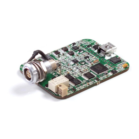
PalmSens EmStat3+ User manual

Getting started with the EmStat3+
module for OEM
OEM Interface for electrochemical sensors
Last revision: May 27, 2015
© 2015 PalmSens BV
www.palmsens.com

2 Getting started with the EmStat3+ module for OEM
Getting started with the EmStat3+ module for OEM
Contents
1Introduction ....................................................................................................................................... 3
1.1 EmStat communications........................................................................................................... 3
1.2 USB or serial / TTL ................................................................................................................... 3
1.3 Baudrate settings ..................................................................................................................... 4
1.4 Connecting to PC via RS232 converter .................................................................................... 4
2Printed Circuit Board Layout ............................................................................................................. 5
2.1 CON1 description..................................................................................................................... 5
2.2 CON2 description..................................................................................................................... 6
2.3 Heat transfer............................................................................................................................. 6
2.4 Pinout of sensor plug................................................................................................................ 7
3Firmware ........................................................................................................................................... 8
4Instrumental specifications ................................................................................................................ 9
4.1 Power requirements ................................................................................................................. 9
Appendix A: Change EmStat USB connection to virtual COM port ......................................................... 10

Getting started with the EmStat3+ module for OEM 3
Getting started with the EmStat3+ module for OEM
Important before you start
unpacking
Please read this quick start guide carefully before unpacking the boards from their
antistatic bags or using the kit, as it contains important information on how to avoid
damage to the PCB’s.
1Introduction
The EmStat-series are potentiostats with an embedded microcontroller. They provide all the major
potentiostatic techniques with automatic current ranging and peripheral control.
1.1 EmStat communications
The EmStat is interfaced to a PC or host controller by means of a powered USB bus or serial (TTL) port.
The instrument can be used with the Windows program PSTrace. The Software Development Kit (SDK) of
PalmSens is compatible with EmStat.
The instrument can also be controlled by using the commands as described in the ‘Communications
protocol’.
1.2 USB or serial / TTL
EmStat3+ is normally controlled and power via its mini USB port. This requires PalmSens drivers to be
installed (automatically installed with PSTrace or the .NET SDK).
Optionally the USB port can be re-programmed to function as a virtual COM port, see appendix A.
EmStat3+ can also be controlled from a host controller by means of Tx and Rx (5V TTL). Use the
following pins for TTL communications (see next page for pin locations):
CON2 - pin 12: +5V power supply (500 mA min.)
CON2 - pin 11: GND (or CON2 –pin 6)
CON2 - pin 1: Tx
CON2 - pin 2: Rx
The EmStat board can be damaged by static electricity (electrostatic
discharge or ESD). Please take adequate precautions against static
discharge during handling.
Make sure the USB chip is not programmed as
VCP (Virtual COM port) when using the Rx/Tx lines on CON2.

4 Getting started with the EmStat3+ module for OEM
Getting started with the EmStat3+ module for OEM
When using RS232, it is advised to use short wires (max. 10 cm) to the controller in order to prevent
‘reflections’. If serial communications is required in order to control the device directly from a PC without
using the PalmSens drivers, it is advised to change the EmStat’s USB port to function as Virtual COM
port. See also appendix A.
1.3 Baudrate settings
The EmStat module has been set to a default baudrate of 230400 baud.
This baudrate is supported by PSTrace. PSTrace also supports 57600 baud.
The baudrate has the following influence on the maximum scanrate for measurements;
Baudrate
Max. number of
data points / second
Min. interval time
230400
1000
1.00 ms
57600
197
5.07 ms
It is possible to change the baudrate setting of the EmStat module in the firmware (requires firmware v7.0
or higher).
See the EmStat Communications Protocol section 4.6: Changing the baudrate.
The firmware update program will always be able to update the firmware regardless of the baudrate
supported by the firmware.
See section Firmware in this document on how to update the firmware using a serial connection.
1.4 Connecting to PC via RS232 converter
Connect the SparkFun TTL-RS232 converter or any other similar converter as following:
EmStat has a default baud rate of 230400 baud.
This baudrate is generally not supported by the COM port on a regular
desktop PC.
For communications using RS232 a baudrate of 57600 is advised.
See also section 1.3
If using a null modem cable
between EmStat and
PC/controller:
EmStat:
RX: CON2 –PIN2
TX: CON2 –PIN1
VCC: CON1 –PIN5
GND: CON1 –PIN6
If connecting directly to
PC/controller:
EmStat:
RX: CON2 –PIN1
TX: CON2 –PIN2
VCC: CON1 –PIN5
GND: CON1 –PIN6

Getting started with the EmStat3+ module for OEM 5
Getting started with the EmStat3+ module for OEM
2Printed Circuit Board Layout
EmSta3+ PCB layout
The board has two pin headers: CON1 and CON2
CON1 is used to connect for instance the MUX multiplexer or any other peripheral.
CON2 is used when serial TTL communications is used and provides also an external analog input and
analog output line, with a range of 0 - 4.095 V.
2.1 CON1 description
Pin Function
1Digital outputline d3 or can function as digital input line 0
2Digital outputline d2
3Digital outputline d1 reserved for switch box: 1 = off 0 = on
4Digital outputline d0 reserved for switch box: 0 = off 1 = on
5Output: 5 V digital (max. 30 mA when powered from USB),
or input (if not powered from USB): 5 V power supply (100 mA min.),
6DGND
710 V analog (adviced max. 50 mA)
8Sense
9AGND (connect to metal housing / cable shielding)
10 WE
11 RE
12 CE
The digital I/O lines are at 5V.

6 Getting started with the EmStat3+ module for OEM
Getting started with the EmStat3+ module for OEM
2.2 CON2 description
Pin Function
1Tx (serial port)
2Rx (serial port)
3Reserved (DO NOT CONNECT THIS PIN)
4Voltage reference (4.096 V)
5Reserved for use with external interrupt signal
6DGND
7Reset (active high)
8Download (active low)
9ADC ch.2 (range 0 –4.095 V)
10 DAC ch.1 (range 0 –4.095 V) The load must have an impedance of at least 5 kohm.
11 DGND
12 5 V power supply (500 mA min.), if not powered from USB
2.3 Heat transfer
IC17 may dissipate about 1 Watt or even higher when the output current limit is set higher.
It is therefore advised to make a thermal connection from the bottom side of the PCB to something which
can absorb heat, for instance using the thermal pad WX-3009-0227-6 from 3M, available from Farnell.
An adhesive heat sink like BGA-STD-015 is available from Farnell (2084425).
Adhesive heat sink
It is advised to make a thermal connection from the bottom side of the PCB
to something which can absorb heat like a housing or heat sink.

Getting started with the EmStat3+ module for OEM 7
Getting started with the EmStat3+ module for OEM
2.4 Pinout of sensor plug
See CON4 on page 2.
Front view of socket
Solder side of socket
1 ●●4
2 ●●3
4 ●●1
3 ●●2
1. RE: blue connector or reference electrode
2. CE: black connector or counter electrode
3. S: red female/male connector or sense
4. WE: red connector is working electrode
The shield of the cable must make contact with the metal case of the
sensor connector or AGND.

8 Getting started with the EmStat3+ module for OEM
Getting started with the EmStat3+ module for OEM
3Firmware
The firmware of EmStat is downloaded by using the program ‘Update firmware’. The EmStat with USB
interface is updated automatically.
The serial version of EmStat requires the use of CON2.
Follow these steps:
-Remove the power supply from EmStat
-Connect pin 8 (download - active low) to pin 6 (GND).
-Connect the power supply
-Run program ‘Update firmware’
-Press ‘Connect’
-Load firmware file ESx##, where x is the EmStat type and ## the firmware version.
-Make sure the checkbox ‘PalmSens or EmStat is on, but does not work property' is checked
-Click button 'Update Firmware'.
-Remove the power supply briefly to force a reset
-Wait until updating has finished.
-Remove the connection between pin 8 and 6.
-Re-connect the power supply.

Getting started with the EmStat3+ module for OEM 9
Getting started with the EmStat3+ module for OEM
4Instrumental specifications
Specifications of the EmStat3+ module:
- dc-potential range
- compliance voltage
- applied dc-potential resolution
- dc-offset error
- accuracy
- current ranges
- maximum measured current
± 4.000 V
± 8 V
0.125 mV
3 mV
≤ 0.3 %
1 nA to 100 mA (9 ranges)
using a ZRA (zero resistance
ammeter)
± 100 mA typical
- current resolution 0.1 % of current range
1 pA on lowest current range
- accuracy ≤ 0.5 % of current range at 10 nA and ≤ 1 % at 1 nA
≤ 0.2 % at 100 nA to 100 uA
≤ 0.5 % at 1 mA, 10 mA and 100 mA
all with additional 0.2 % offset error
- electrometer amplifier input > 100 Gohm // 4 pF
- rise time approx. 100 μs
- power 5 V, 130 mA (ES3) or 500 mA (ES3+) from USB connector
- interfacing USB
- external I/O options analog: 1 input and 1 output channel (both 0 V - 4.096 V)
digital: 4 in/output lines (maximum rating: -0.3 V to 5.3 V)
- sensor connection shielded cable with circular connector for WE, Sense (ES3+),
RE and CE.
4.1 Power requirements
Power from USB port:
-Cell off 10 mA: 0.220 A
-Cell off 100 mA: 0.257 A
-Cell on 10 mA, with 10 mA output current: 0.277 A
-Cell on 100 mA, with 50 mA output current: 0.440 A

10 Getting started with the EmStat3+ module for OEM
Getting started with the EmStat3+ module for OEM
Appendix A: Change EmStat USB connection to virtual
COM port
1. Connect EmStat to the USB port.
2. Open FT_PROG (see http://www.ftdichip.com/Support/Utilities.htm)
3. Click the “Scan and Parse” button
4. Change the Custom VID/PID to FTDI Default:
5. Uncheck the checkbox “Load D2XX Driver”:
6. Make sure all “Invert RS232 Signals” settings are unchecked:
7. Click the “Program Devices” button
8. Click the “Scan and Parse” button again to check if the settings are written correctly,
especially the invert DTR# setting. If this setting cannot be changed, please contact us. Your
FT_PROG version might have a bug.
9. Remove the USB cable and insert again.
10. Your PC will now have found a virtual COM port which can be used to communicate with
EmStat.
11. The com port number can be found in the Device Manager found in Windows Configuration. You
can also press [windows key] + [pause] on your keyboard to find the Device Manager.
Make sure the USB chip is not programmed as
VCP (Virtual COM port) when using the Rx/Tx lines on CON2.
Select FTDI Default
Uncheck “Load D2XX Driver”
Other manuals for EmStat3+
1
Table of contents
Other PalmSens Control Unit manuals
Popular Control Unit manuals by other brands

Texas Instruments
Texas Instruments bq34210-Q1 Technical reference manual

Mitsubishi Electric
Mitsubishi Electric A1SJ71AP23Q user manual

Nordson
Nordson WM 480 manual

KUGELHAHN MÜLLER
KUGELHAHN MÜLLER KM-O Series Operating and maintenance instructions

VIA Technologies
VIA Technologies QSM-8Q60 user manual

Raritan
Raritan COMMANDCENTER 2.20 - user guide