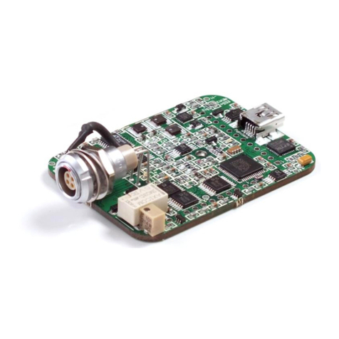
PalmSens EmStat3-MUX8 User manual

EmStat3-MUX8 for OEM
Connecting a MUX8 board to an EmStat3
Last revision: May 27, 2015
© 2015 PalmSens BV
www.palmsens.com

2 EmStat3-MUX8 for OEM
EmStat3-MUX8 for OEM
Contents
1EmStat3 PCB................................................................................................................................... 3
2Connecting EmStat board to MUX8 multiplexer ................................................................................ 3
2.1 CON1 description..................................................................................................................... 4
2.2 CON2 description..................................................................................................................... 4
2.3 Pinout of sensor connector (CON4): ......................................................................................... 4
2.4 CON1 to MUX8 ........................................................................................................................ 5
3MUX8 PCB........................................................................................................................................ 5
3.1 Functional diagram ................................................................................................................... 5
3.2 Set standby potential with the Vaux pin .................................................................................... 6
3.3 MUX8 configurations ................................................................................................................ 7
3.4 Electrode connections .............................................................................................................. 9
3.5 Specifications ........................................................................................................................... 9
4PCB dimensions.............................................................................................................................. 10
4.1 MUX8 PCB ............................................................................................................................. 10
4.2 EmStat3PCB.......................................................................................................................... 11
4.3 PCB’s connected –option 1................................................................................................... 12
4.4 PCB’s connected – option 2................................................................................................... 13

EmStat3-MUX8 for OEM 3
EmStat3-MUX8 for OEM
Important before you start
unpacking
Please read this quick start guide carefully before unpacking the boards from their
antistatic bags or using the kit, as it contains important information on how to avoid
damage to the PCB’s.
1EmStat3 PCB
The EmStat-series are potentiostats with an embedded microcontroller. They provide all the major
potentiostatic techniques with automatic current ranging and peripheral control.
2Connecting EmStat board to MUX8 multiplexer
EmStat3 PCB layout
The board has two pin headers: CON1 and CON2
CON1 is used to connect for instance the MUX multiplexer or any other peripheral.
CON2 is used when serial TTL communications is used and provides an external analog input and analog
output line, with a range of 0 - 4.095 V and a digital input line.
The EmStat and MUX boards can be damaged by static electricity
(electrostatic discharge or ESD). Please take adequate precautions against
static discharge during handling.
See document “EmStat3 for OEM.pdf” for more information about interfacing with the
EmStat3 board.

4 EmStat3-MUX8 for OEM
EmStat3-MUX8 for OEM
2.1 CON1 description
Pin Function
1Output line 3 reserved for Mux16 or digital input line 0
2Output line 2 reserved for Mux16/8
3Output line 1 reserved for Mux16/8 and switch box
4Output line 0 reserved for Mux16/8 and switch box and stirrer: 0 -off 1 - on
5Output: 5 V digital (max. 30 mA when powered from USB),
or input (if not powered from USB): 5 V power supply (100 mA min.),
6GND
75 V analog (max.20 mA when powered from USB)
8–5 V analog (max. 10 mA)
9AGND
10 WE
11 RE
12 CE
2.2 CON2 description
Pin Function
1Tx (serial port)
2Rx (serial port)
3Reserved (DO NOT CONNECT)
4Voltage reference (4.096 V)
5Reserved
6GND
7Reset (active high)
8Download (active low)
9ADC ch.2 (range 0 –4.095 V)
10 DAC ch.1 (range 0 –4.095 V)
11 GND
12 5 V output if powered via USB
2.3 Pinout of sensor connector (CON4):
1 ●●4
2 ●●3
1. RE: blue connector or reference electrode
2. CE: black connector or counter electrode
3. Not connected
4. WE: red connector is working electrode
IMPORTANT:
The shield of the cable must make contact with the metal case of the sensors connector.

EmStat3-MUX8 for OEM 5
EmStat3-MUX8 for OEM
2.4 CON1 to MUX8
EmStat is to be connected to the MUX board using CON1. This can be done in two ways:
Two ways of connecting the EmStat PCB to the MUX8 PCB
3MUX8 PCB
The MUX8 multiplexer is meant for use with 2- or 3- electrode sensors or cells up to 8 channels.
3.1 Functional diagram

6 EmStat3-MUX8 for OEM
EmStat3-MUX8 for OEM
3.2 Set standby potential with the Vaux pin
The Vaux pin can be used to set a standby potential on all unselected channels.
Make sure the following jumpers are placed:
-Unselected WE to AGND: NOT PLACED
-Unselected WE to standby potential: PLACED
When using Conf 1 and CE and RE are multiplexed (J4 and J5 are placed), the Vaux will not be applied
on the unselected channels since only the selected channel’s WE, CE and RE are polarized.
The Vaux pin can be connected to CON2 –pin 10 (DAC) of the EmStat to control the standby potential.
In PSTrace the DAC pin can be set in the Analog Out window in the Manual Control tab:
Also the ‘SetAnalog’ command can be used in the Scripting window.

EmStat3-MUX8 for OEM 7
EmStat3-MUX8 for OEM
3.3 MUX8 configurations
The multiplexer can be used in different configurations or modes. Each configuration is set by a
number of jumpers which are located on the board as shown in the illustration of the board layout
below.
Possible sensor configurations are:
Sensor arrays with (up to) eight working, reference and counter electrodes
Sensor arrays with eight working and eight combined reference/counter electrodes
Sensor arrays with eight working electrodes sharing a reference and a counter electrode
Sensor arrays with eight working electrodes sharing a combined reference/counter
electrode
In all configurations the sensors can be multiplexed, leaving the not-selected sensors or cells at
open circuit.
Sensor configurations 2, 3 and 4 have the possibility to leave not-selected sensors or cells at open
circuit or to apply the same potential to all sensors or cells.
Jumpers:
J1: RE to CE
Is placed when the sensor has a combined reference and counter electrode. This jumper therefore
connects RE to CE.
J2: CE Direct
If the sensor array has more than one working electrode, but one counter and/or reference
electrode, this jumper is placed. CE from PalmSens is connected directly to pin 1 and pin 2 of CON1
J3: RE Direct
If the sensor array has more than one working electrode, but one counter and/or reference, this
jumper is placed. RE from PalmSens is connected directly to pin 13 and 14 of CON1
J4: CE MUX
This jumper is placed if CE has to be multiplexed. This is the case when each of the sensors has its
own counter electrode using pin3 to 10.
J5: RE MUX
This jumper is placed if RE has to be multiplexed. This is the case when each of the sensors has its
own reference electrode using pin 15 to 22
J6: Unselected WE to AGND:
If placed, all unselected working electrodes or sensors will remain polarized at the potential set by
the PalmSens or EmStat. If this jumper is not placed only the selected channel is polarized leaving
the not-selected WE’s at open circuit.
When using Conf 1 and CE and RE are multiplexed (J4 and J5 are placed), this jumper is not
relevant since only the selected channel’s WE, CE and RE are polarized.
J7: Unselected WE to standby potential
See section 3.3

8 EmStat3-MUX8 for OEM
EmStat3-MUX8 for OEM
Jumper settings for the available configurations:
Conf. 1: Sensor array with up to eight working, eight reference and eight counter electrodes:
Jumpers to be placed are: J4 and J5
The potential is only applied to the selected channel. All channels NOT selected are at open
circuit. (See remark below *)
Conf. 2a: Is suitable for working with a sensor array which has up to eight individual electrochemical
cells consisting of up to eight working and eight combined reference/counter electrodes:
Jumpers to be placed are: J1, J4 and J5
Note: all leads CE1-8 and RE1-8 are connected together and this combined lead is
connected to all eight combined reference/ counter electrodes.
The potential is only applied to the selected channel. All channels NOT selected are at open
circuit. (See remark below *).
When J6 is also placed, the potential is applied to all working electrodes continuously.
Conf. 2b: Sensor array with up to eight working and eight combined reference/counter electrodes:
Jumpers placed are: J1, J2 and J3
Note: the combined reference/counter electrodes are connected to the leads CE Direct
and/or RE Direct
When J6 is also placed, the potential is applied to all working electrodes continuously.
Conf. 3: Sensor array with up to eight working electrodes all sharing one reference and one counter
electrode:
Jumpers placed are: J2 and J3
Note: the reference and counter electrodes are connected to RE Direct and CE Direct
respectively.
When J6 is also placed, the potential is applied to all working electrodes continuously.
Conf. 4: Sensor array with up to eight working electrodes all sharing one combined
reference/counter electrode:
Jumpers placed are: J1, J2 and J3
Note: the reference/counter electrode is connected to RE Direct and/or CE Direct.
When J6 is also placed, the potential is applied to all working electrodes continuously.
*IMPORTANT REMARK
It is not possible to apply a potential simultaneously to more than one sensor or cell each with three
electrodes. This requires a multipotentiostat, one potentiostat for each channel. This is however
possible with two electrode sensors or cells, so when combined counter and reference electrodes
are applied.

EmStat3-MUX8 for OEM 9
EmStat3-MUX8 for OEM
3.4 Electrode connections
3.5 Specifications
Number of channels
2-8
Multiplexer use:
Sensor arrays with up to eight working, reference and counter
electrodes
Sensor arrays with up to eight working and eight combined
reference/counter electrodes
Sensor arrays with up to eight working electrodes all sharing
the same reference and the same counter electrode
Sensor arrays with eight working electrodes all sharing the
same combined reference/counter electrode
On resistance
WE, CE and RE channels: 2 ohm typical (see note)
Leakage current
10 pA typical at 25 ºC (see note)
Charge injection
20 pC typical (see note)
Connections:
Shielded flat cable, with stripped end leads or
by means of the MUX8 Terminal Block (in shielded housing)
eight WE’s
eight CE’s
eight RE’s
one CE used when all WE’s share one counter electrode
one RE used when all WE’s share one reference electrode
analogue ground for shielding
Dimensions of PCB
76 x 74 mm

10 EmStat3-MUX8 for OEM
EmStat3-MUX8 for OEM
4PCB dimensions
4.1 MUX8 PCB

EmStat3-MUX8 for OEM 11
EmStat3-MUX8 for OEM
4.2 EmStat3PCB

12 EmStat3-MUX8 for OEM
EmStat3-MUX8 for OEM
4.3 PCB’s connected – option 1
variable
(>18 if mini USB is used)
25

EmStat3-MUX8 for OEM 13
EmStat3-MUX8 for OEM
4.4 PCB’s connected – option 2
101,30
variable
16
Table of contents
Other PalmSens Control Unit manuals
Popular Control Unit manuals by other brands

Allen-Bradley
Allen-Bradley ControlNet 1747-ACN15 user manual

Arkel
Arkel ARCODE 4B26A Hardware manual

Watts
Watts AMES 2000SS Series INSTRUCTION, INSTALLATION, MAINTENANCE AND REPAIR MANUAL

Honeywell
Honeywell D05FS installation instructions

beier
beier AKL-8-W Operation manual

Daikin
Daikin BRC1E71 Engineeiring data