Panamorph UH480 User Manual and Installation Guide, Version 1.7, copyri ht February, 2011, all ri hts reserved.
Pa e 6
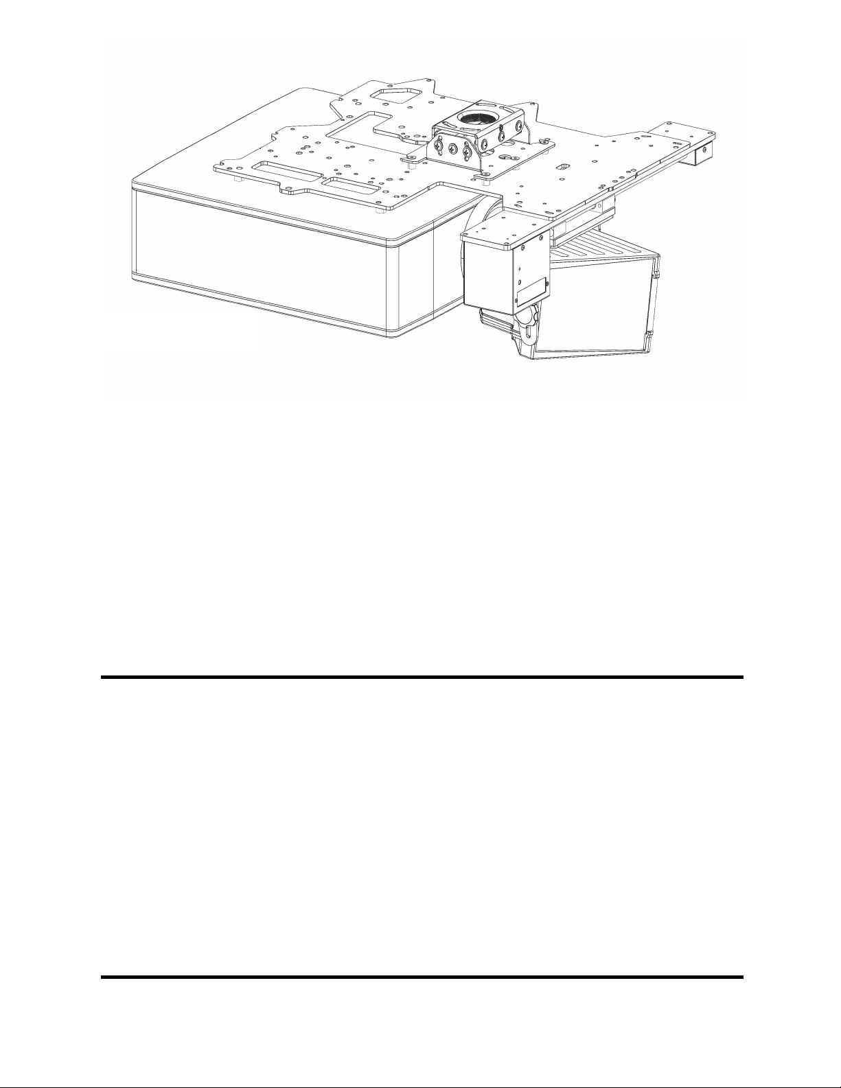
MOUNTING THE MTH1 TRANSPORT
Installin without AKPro attachment kits. The MTH1 may be mounted directly to ceilin
structures without usin the AK attachment kits. Two black #10x1¼” lon mountin screws are
included with the MTH1 for mountin throu h the centers of the two ceilin mount slots in the
MTH1 body. These centers should correspond to two mountin points in a secure platform in
front of your projector so that the UH480 can be properly positioned in front of and as close to
the projector lens as possible without mechanically interferin with the projector or its
ventilation in either “lens in” or “lens out” positions. However, the optical desi n of the UH480
is very for ivin , so minor deviations in this positionin or any moderate warmin around a
projector vent will have no impact on ima e quality. In addition, note that in a ceilin mounted
system, the center of your projector beam will exit the projector lens below center. The UH480
will ultimately be ali ned with the beam itself and not the projector lens. As a result, you
should expect the UH480 to be centered below the projector lens and, ultimately, tilted sli htly
downward. Before finally ti htenin the mountin screws, refer to the “Final Adjustments” step
below.
1. Remove the UH480 Lens from its Lens Bracket by removin the two Lens Knobs.
Securely attach the UH480 Lens Bracket to the MTH1 shuttles usin the ei ht M3x6mm brass
screws and black washers included in the MTH1 kit. The Lens Bracket should be oriented so
that its central threaded hole is ali ned with the lon slot in the body of the MTH1.
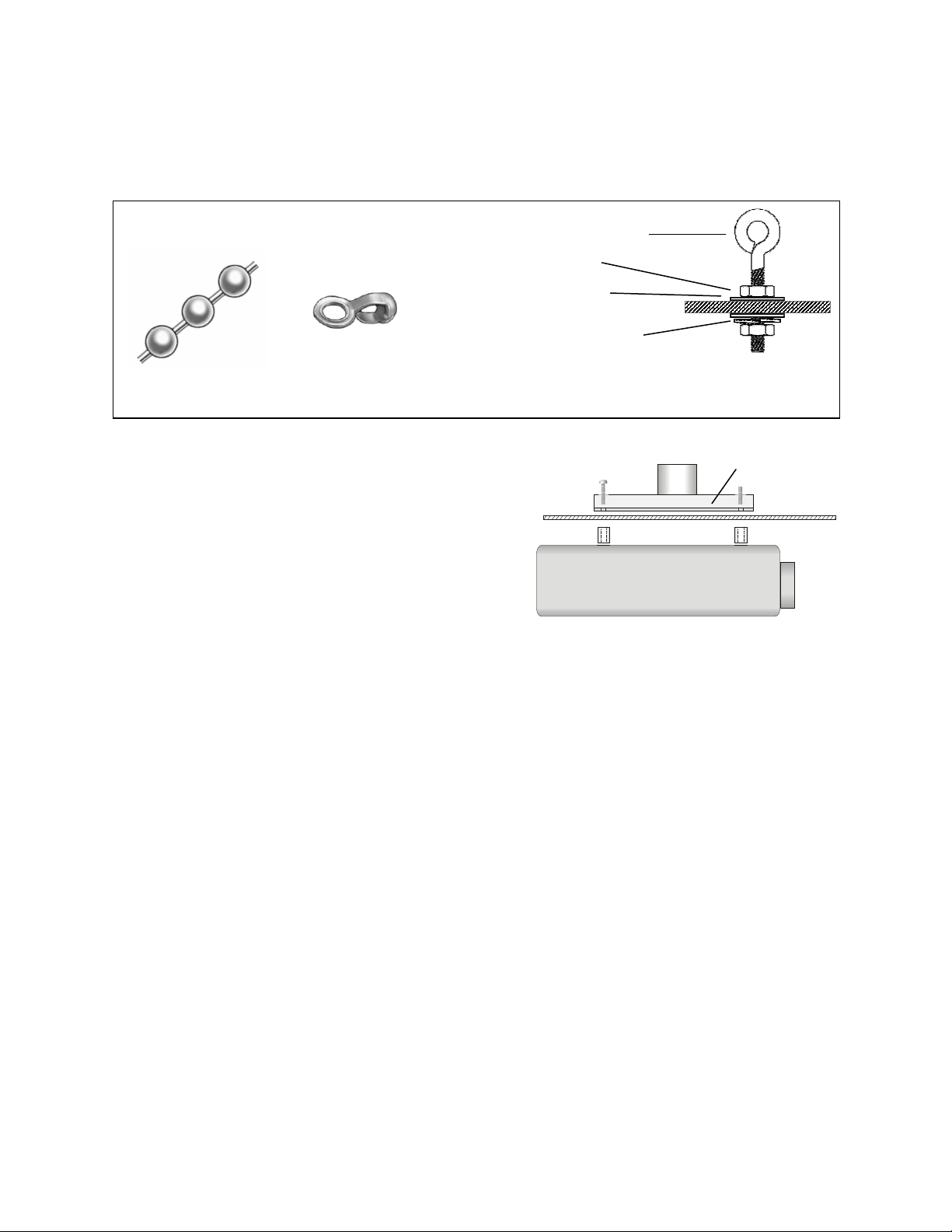
2. If usin an AK attachment kit, position the MTH1 to the bottom of the installed AK
Attachment Plate so that the detailed side (front) of the MTH1 body is facin the projection
screen. Insert each of the four M3x16mm Phillips screws throu h a lock washer and flat
washer from the MTH1 kit, throu h the four “M” slots in the Attachment Plate and into the
correspondin holes in the MTH1 body. Ti hten only to the point that the MTH1 is a ainst the
Attachment Plate but is still relatively free to be oriented or “pivoted” in the “M” slots.
3. The UH480 Lens may include a lo o plate in a pouch attached to the side of its box.
Use the wrench included to attach the lo o plate to the lens. It does not matter which side of
the Lens housin is up or down. Now carefully install the Lens into the Lens Bracket usin the
two Lens Knobs. Proceed to “Final Adjustments” step below.
MOUNTING THE ATH1 TRANSPORT
1. DO NOT CONNECT POWER TO THE TRANSPORT AT THIS TIME.
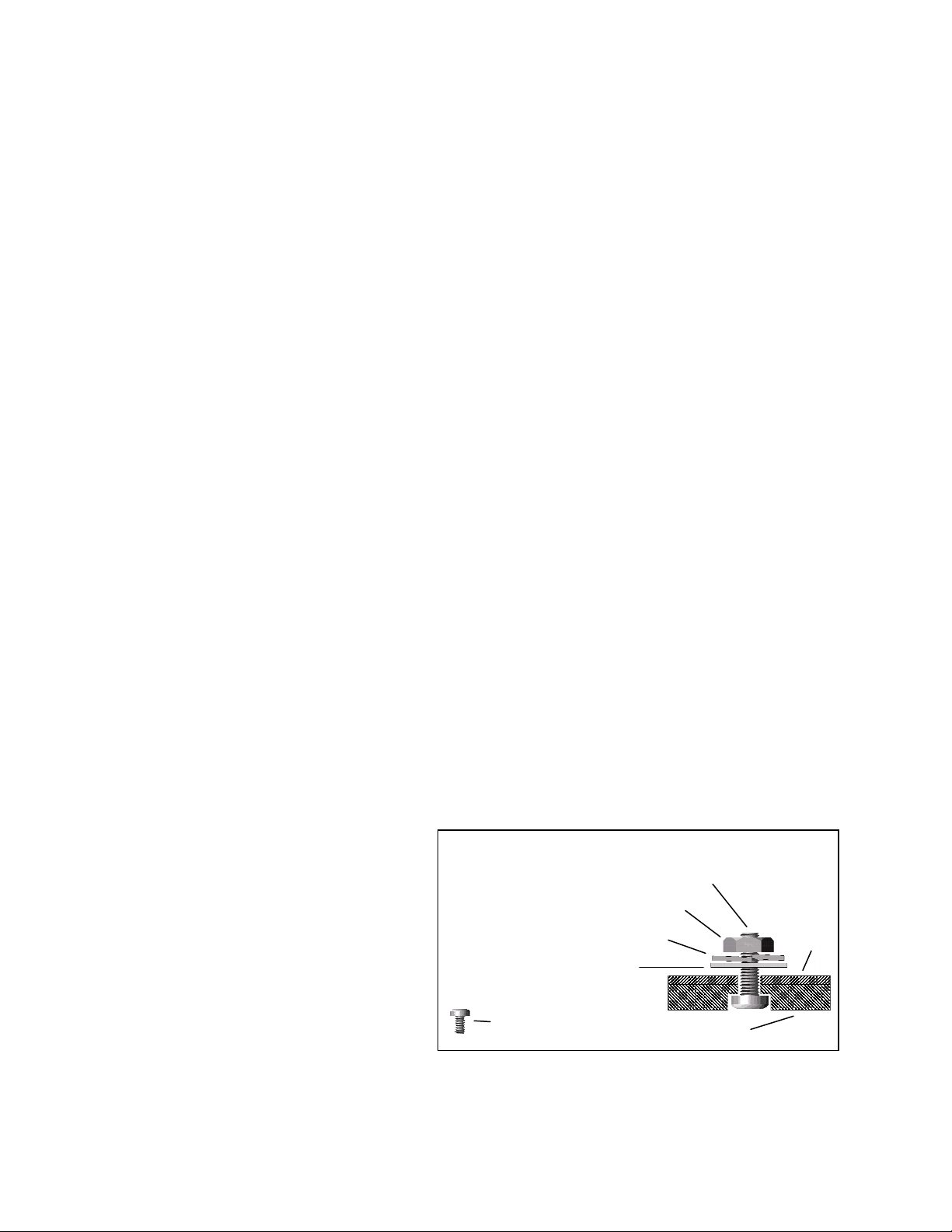
2. Position the flat side of the
motorized transport a ainst the bottom
of the Attachment Plate so that the
transport lo o is toward the screen and
the center “C” hole in the Attachment
Plate is ali ned with the front recessed
transport hole. Insert the #10-32 pivot
screw up throu h the transport and
Attachment Plate and loosely complete
the assembly with the correspondin
washer, lock washer and nut. Now
loosely insert the four #6-32 3/8” screws
throu h the four “M” slots in the top of the Attachment Plate and down into the transport.
3. Refer to the ATH1 user manual (included with ATH1) for additional instructions to install
the lens at this time, but do not for et to complete the “Final Adjustments” step below.
ATH1 Attachment Ba Contents
#6-32x3/8” screw (4)
#10-32x5/8” screw (1)
#10-32 lock washer (1)
#10-32 washer (1)
#10-32 nut (1)
assembled
Plate


 4.5/55 Operation manual")