8A3 G97 0000 1
M0213M0
ON
1234
ON
1234
ON
1234
ON
1234
ON
1234
ON
1234
ON
1234
ON
1234
ON
1234
ON
1234
ON
012
X
3
1 2 3 4
RS-485
MODBUS(RTU)
38,400bps
1-bit
1-bit
1-bit(Parity:odd)
1to63
0
1
2
Y
3
2013
Unable to
communicate
Unable to detect
The detection state
does not last.
Erroneous
detection
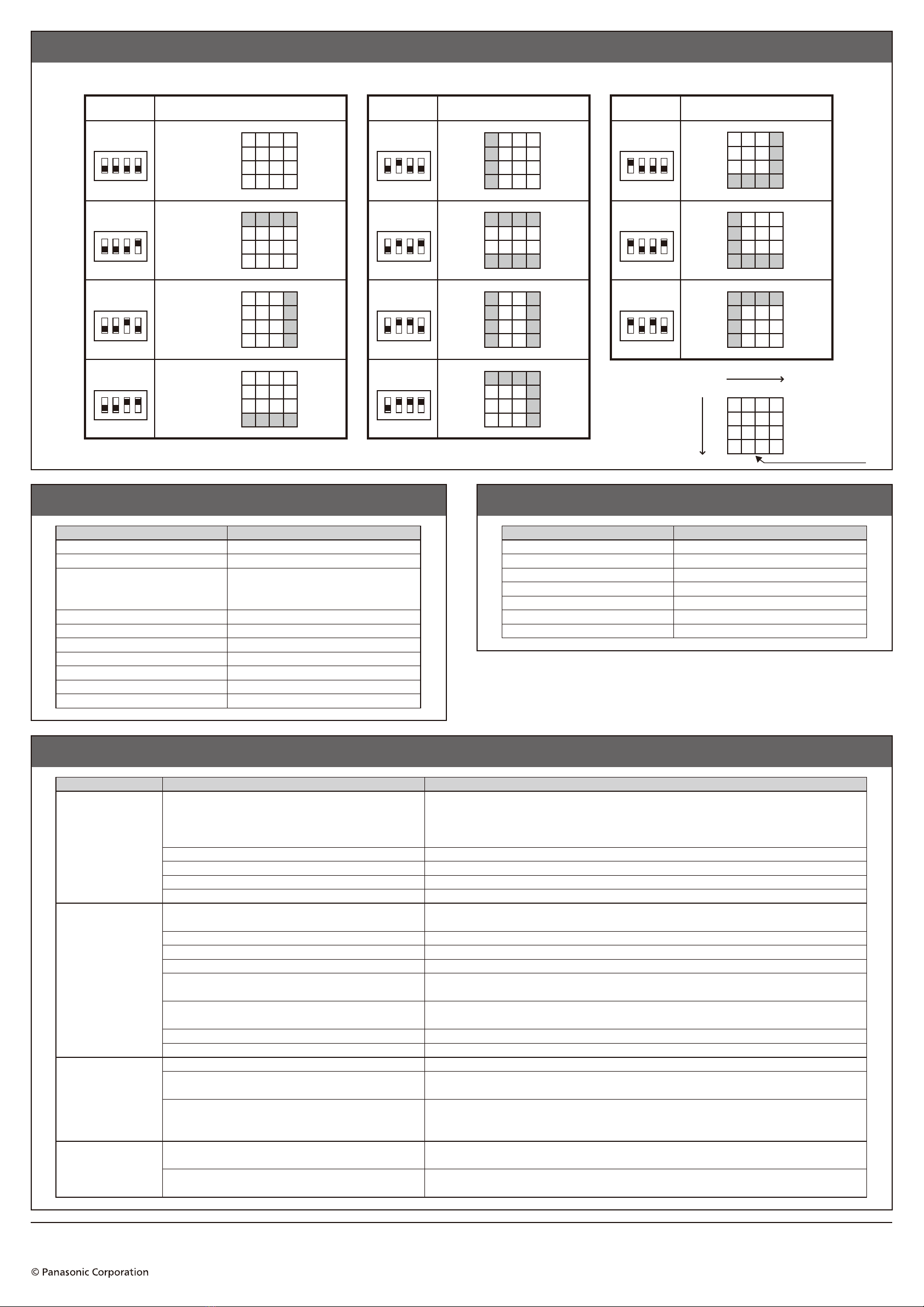
Area Mask Function
Setting the 4-bit switch enables the masking of the detection area. (The shaded area will not be detected.) Press the reset switch after setting changes.
Setting SettingSetting
Mask setting area Mask setting area Mask setting area
No masking
Coordinates
The operation
lamp side
Ratings/Specifications Communication Specifications
Items Specifications Items Specifications
Rated voltage
Detection range (at a position 1.6 m away from the ceiling)
Detection object movement speed
Detection position accuracy
Detectable number of people
Room temperature allowing human detection
Output coordinates
Operation lamp
Contact output
Maximum wiring length
24 V DC
□3.6 m
1.7 m/s (6 km/h) or lower
(Rapid movements may not be detected
depending on the temperature difference with
the background)
±500 mm (when seated)
8 or less (2 or less in □1.8 m)
10ºC to 29ºC (May not be detected due to clothing)
16 divisions (4×4)
Illuminates red when a human body is detected
Outputs ON when a human body is detected (DC 24 V, 0.1 A or less)
500 m or less
Communication method
Communication protocol
Baud rate
Start bit
Stop bit
Parity bit
Communication address setting range
Q&A for Operation Check
State Possible causes Check/Action
Communication cables are not correctly inserted or connected.
Communication settings do not agree with those of the control device.
Termination-side device is incorrectly connected.
Termination setting is not specified on the control device.
Addresses are not set, or the address of a device coincides
with that of other devices.
Connect the communication cables correctly to the quick-connection terminals.
Check the communication specifications and set the control device to match. (Baud rate, start bit, stop bit, and parity bit)
Check the connection status of the termination-side device and connect correctly.
Check the manual, etc. of the control device and specify the correct termination setting.
All the devices connected to the communication line of a control device must have different addresses.
Check the address setting status and specify an address different from the other devices.
Press the reset switch after setting changes.
The setting changes are not effective until the reset switch is pressed.
The temperature difference with the background temperature is small.
The background temperature is higher than that of human subjects.
The detection area is not correctly arranged.
High moving speed
A person remains still near the edge of an area.
The installation height exceeds 2.7 m.
The area mask setting is enabled.
The protection film is left unremoved on the main body.
Moving objects such as animals, moving devices, etc.
are within the detection area.
Residual heat on a chair, etc., is detected after a person has
gotten up and left.
A person remained still or did not move much for a long period of time.
A person remains still near the edge of an area.
A person entered the area with another person in mutual
proximity and remained still after separating.
The product's detection operation is carried out based on the principle of using the temperature difference with the background,
therefore moving objects that have a temperature difference with the background are difficult to distinguish from human bodies
and thus may be erroneously detected.
A chair in contact with a human body has the same temperature as the body and may thus be detected even after
the occupant has gotten up and left.It will not be detected once the temperature drops.
The detection terminates when unable to recognize any movement for more than 90 minutes.
The product recognizes moving processes within the detection area to detect a human body.
If it stops moving immediately after entering the area and remains still, the product may not be able to recognize
its movement adequately and thus may revise its determination from a human body to an object.
A group of people positioned close to each other may be recognized as one person.
A person is recognized as an object upon separating from another person in the area, and may not be
determined as a human body if he/she remains still after the separation.
Remove the protection film after installation.
Area masking setting disables the detection of the masked area.
If the installation height is too high, a human body will be further away from the product main body. As a result,
the size of the human body will appear relatively small and its temperature low, making detection more difficult.
The product's detection operation is carried out based on the principle of using the temperature difference with the
background, therefore a human body may not be detected when the difference between its surface temperature and
the background temperature is very small due to cold weather gear, etc.
A human body cannot be detected when its temperature is lower than the background.
Check whether the installation allows for the correct orientation of the detection area (quadrangular pyramid shape).
A human body may not be detected when it moves fast.
The product recognizes moving processes within the detection area to detect a human body.If it stops moving immediately after
entering the area and remains still, the product may not be able torecognize its movement and thus may not recognize it as a human body.
Device Solutions Business Division, Automotive & Industrial Systems Company, Panasonic Corporation
5 Ii, Awara-City, Fukui 919-0697, Japan


 User manual")


