manuals.online logo
Brands
  1. Home
  2. •
  3. Brands
  4. •
  5. TEKTELIC Communications
  6. •
  7. Accessories
  8. •
  9. TEKTELIC Communications T0006623 User manual

TEKTELIC Communications T0006623 User manual

2020 TEKTELIC Communications Inc. v1.2 1/2
T0006623
SMART AC OUTLET
USER GUIDE
DESCRIPTION
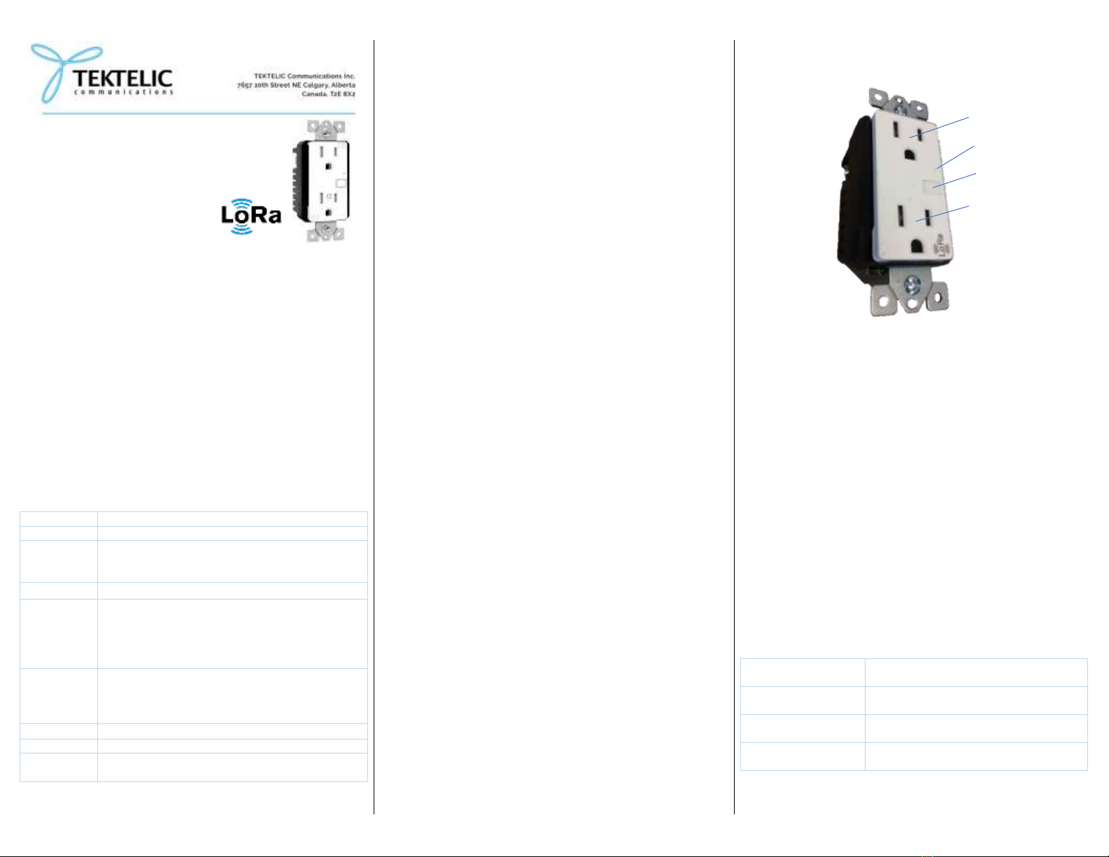
The Smart AC Outlet has the form factor of a standard NEMA 5-15R
Decorator style duplex tamper-resistant receptacle but incorporates a
LoRa radio with power control and monitoring circuitry which allows for
the following remote user features:
Power on-off control and status
Measurement of consumed energy (kWh), line voltage (Vrms),
load current (Arms), load power (real, reactive, and apparent,
W), line frequency (Hz), and load power factor.
Note that only the lower receptacle is controlled and monitored, the top
receptacle is always live when line power is connected to the module
and any connected load does not contribute to the energy monitoring.
The Smart AC Outlet also has a momentary contact push-button switch
located on the faceplate for local user on-off control of the controlled
receptacle as well as an LED for local status indication.
SPECIFICATIONS
Dimensions
43 mm (1.7”) W x 46 mm (1.8”) D x 104 mm (4.1”) H
Weight
0.12 kg (0.26 lb)
Operating
Environment
Indoor residential & commercial
0 to 40 °C (-40 to 104 °F)
5 - 95% non-condensing RH
Line
120 VAC, 60 Hz, 15 A circuit
Load
1800 W (15 A) Resistive
1000 W Incandescent
5 A Electronic ballast
1200 VA Standard ballast
½ HP Motor
Wire
Termination
Max. 2 wires per terminal except 1 wire for Ground
#14 AWG copper or copper clad solid conductor
16 mm (5/8”) strip length
Torque terminal screw to 2.3 N.m (20 lbf-in)
Surge Prot.
IEEE C62.41 Category A
Air Interface
LoRa US915 (902 - 928 MHz) Class C
Approvals
UL pending
FCC Pt. 15, RSS-247, FCC Pt. 27 pending
WARNINGS AND PRECAUTIONS
TO AVOID FIRE, SHOCK, OR DEATH, ALWAYS TURN OFF POWER
at the circuit breaker or fuse panel before wiring the module!
If you are unsure or uncomfortable with installation of this
module, consult an electrician.
To be installed in a standard electrical box and used in
accordance with appropriate electrical codes and regulations.
To be installed with copper or copper clad wires only.
Exercise caution when powering loads from the LoRa radio-
controlled receptacle. Loads connected to this receptacle may
be automatically powered on by a timer or by a remote user.
Such unexpected operation may present a hazardous condition
for local personnel.
This product shall not be used with medical and/or life support
equipment.
INSTALLATION PROCEDURE
1. Locate the electrical box into which the Smart AC Outlet will be
installed.
2. Remove power to the wiring by turning off circuit power at the
circuit breaker or fuse panel.
3. Test the existing wiring to ensure that power has been
removed.
4. Inspect the electrical box, a box depth of at least 2” is required.
The electrical box may be metal or plastic but a plastic box will
result in the best all-around RF performance.
5. Identify the appropriate wiring diagram for your installation
situation.
6. Strip wire insulation back 5/8” (16 mm) and maintain a straight
conductor for each of the wires to be terminated to the
receptacle module.
7. Connect the wires to the module in accordance with the wiring
diagram by inserting the bare wire fully into the wire hole for
each of the Line (Hot), Load, and Ground terminals on the
receptacle module.
8. Once the module is fully wired, push the wiring and the module
into the electrical box, secure the module with the two
mounting ear screws, and install the trim plate with the two
trim plate screws. Always use a plastic faceplate for best RF
reception.
9. Reapply power to the circuit. The module faceplate LED will
now begin to flash indicating connection to a LoRa network is
underway.
10. Connect a load and test using the local on-off button on the
receptacle faceplate.
11. Commission the module on the appropriate LoRa network.
OPERATION
REMOTE OPERATION
The top receptacle is always on and does not contribute to load energy
metering. Only the bottom receptacle is on-off controllable through the
LoRa radio network. By default, the bottom receptacle will be off after
AC power to the module is restored, although this logic can be changed
through the LoRa remote interface.
Measurement of energy supplied by the bottom receptacle as well as
other real-time parametric information including line voltage, load
current, load power (real, reactive, and apparent), and load power factor
is available through the LoRa radio network.
Please refer to the TEKTELIC Communications AC Sensors Technical
Reference Manual (TRM) for details regarding the LoRa network
interface.
LOCAL OPERATION
The bottom, controlled receptacle can be toggled on-off by pressing
momentarily the faceplate control button. By default, this load status
change will be reported over the LoRa network.
The module faceplate has an LED indicator which can be interpreted
according to the following default logic:
Note that this logic may be changed through the LoRa remote interface.
Solid Blue
Load power is OFF
Module is connected to LoRaWAN
Dark
Load power if ON
Module is connected to LoRaWAN
90% On - 10% Off
1s cadence
Load power is OFF
Module is connecting to LoRaWAN
10% On - 90% Off
1s cadence
Load power if ON
Module is connecting to LoRaWAN
LoRa Radio Controlled
Receptacle
Always-on Receptacle
Control Button
LED Indicator
2020 TEKTELIC Communications Inc. v1.2 2/2
WIRING DIAGRAMS
The following diagrams illustrate common installation diagrams, other
options are possible. Always follow appropriate electrical codes and
regulations.
Single Outlet End of Run
Note: An electrical box ground wire is required.
Multiple Outlet Run
Note: An electrical box ground wire is required.
COMPLIANCE STATEMENTS
FCC
This device complies with Part 15 of the FCC Rules. Operation is subject
to the following two conditions:
1. This device may not cause harmful interference, and
2. This device must accept any interference received, including
interference that may cause undesired operation.
To comply with FCC exposure limits for general population /
uncontrolled exposure, this device should be installed at a distance of 20
cm from all persons and must not be co-located or operating in
conjunction with any other transmitter.
Changes or modifications not expressly approved by the party
responsible for compliance could void the user’s authority to operate
the equipment. This equipment has been tested and found to comply
with the limits for a Class B digital device, pursuant to Part 15 of the FCC
Rules. These limits are designed to provide reasonable protection
against harmful interference in a residential installation. This equipment
generates uses and can radiate radio frequency energy and, if not
installed and used in accordance with the instructions, may cause
harmful interference to radio communications. However, there is no
guarantee that interference will not occur in a particular installation. If
this equipment does cause harmful interference to radio or television
reception, which can be determined by turning the equipment off and
on, the user is encouraged to try to correct the interference by one of
the following measures:
Reorient or relocate the receiving antenna.
Increase the separation between the equipment and receiver.
Connect the equipment into an outlet on a circuit different from
that to which the receiver is connected.
Consult the dealer or an experienced radio/TV technician for
help.
IC
This device contains license-exempt transmitter(s)/receiver(s) that
comply with Innovation, Science and Economic Development Canada’s
license-exempt RSS(s). Operation is subject to the following two
conditions:
1. This device may not cause interference.
2. This device must accept any interference, including interference
that may cause undesired operation of the device.
This device should be installed and operated with minimum distance 0.2
m from human body.
Cet appareil contient des émetteurs / récepteurs exemptés de licence
qui sont conformes aux RSS exempts de licence d'Innovation, Sciences et
Développement économique Canada. Son fonctionnement est soumis
aux deux conditions suivantes:
1. Cet appareil ne doit pas provoquer d'interférences.
2. Cet appareil doit accepter toute interférence, y compris les
interférences pouvant entraîner un fonctionnement indésirable de
l'appareil.
Cet appareil doit être installé et utilisé à une distance minimale de 0,2 m
du corps humain.

Other TEKTELIC Communications Accessories manuals

TEKTELIC Communications Kona All-in-One Home Sensor User manual

TEKTELIC Communications

TEKTELIC Communications Kona All-in-One Home Sensor User manual

TEKTELIC Communications T0004437 User manual

TEKTELIC Communications

TEKTELIC Communications T0004437 User manual

TEKTELIC Communications Kona Product manual

TEKTELIC Communications

TEKTELIC Communications Kona Product manual

TEKTELIC Communications Kona All-in-One Home Sensor Series User manual

TEKTELIC Communications

TEKTELIC Communications Kona All-in-One Home Sensor Series User manual

TEKTELIC Communications TUNDRA User manual

TEKTELIC Communications

TEKTELIC Communications TUNDRA User manual

TEKTELIC Communications Kiwi User manual

TEKTELIC Communications

TEKTELIC Communications Kiwi User manual

TEKTELIC Communications T0004893 Product manual

TEKTELIC Communications

TEKTELIC Communications T0004893 Product manual

TEKTELIC Communications T0005982 User manual

TEKTELIC Communications

TEKTELIC Communications T0005982 User manual

TEKTELIC Communications TUNDRA User manual

TEKTELIC Communications

TEKTELIC Communications TUNDRA User manual

Popular Accessories manuals by other brands

Wenger Cupholder Assembly instructions

Wenger

Wenger Cupholder Assembly instructions

Philips DLA81002H brochure

Philips

Philips DLA81002H brochure

RC Lighting LOSBAY800 installation manual

RC Lighting

RC Lighting LOSBAY800 installation manual

Intermec 751G instructions

Intermec

Intermec 751G instructions

WAM TE manual

WAM

WAM TE manual

BS 55 A Series instruction manual

BS

BS 55 A Series instruction manual

PCB Piezotronics 378A06 Installation and operating manual

PCB Piezotronics

PCB Piezotronics 378A06 Installation and operating manual

Griesser Soloscreen Operating and maintenance instructions

Griesser

Griesser Soloscreen Operating and maintenance instructions

BEA IS40 manual

BEA

BEA IS40 manual

Awntech Chicago RC22 Owner’s Manual & Installation Instruction

Awntech

Awntech Chicago RC22 Owner’s Manual & Installation Instruction

DAX HESSAIRE DX4800 Assembly instructions

DAX

DAX HESSAIRE DX4800 Assembly instructions

Omnicomm LLS 30160 user manual

Omnicomm

Omnicomm LLS 30160 user manual

GESTRA LRG 16-9 Installation instructions manual

GESTRA

GESTRA LRG 16-9 Installation instructions manual

Duomo CO233/A Installation and instruction manual

Duomo

Duomo CO233/A Installation and instruction manual

FUTABA SBS-01TAS instruction manual

FUTABA

FUTABA SBS-01TAS instruction manual

Looki DoorEye Plus quick guide

Looki

Looki DoorEye Plus quick guide

Byron DB306 Installation and operation instruction

Byron

Byron DB306 Installation and operation instruction

Elko inels RFDSC-71 quick start guide

Elko

Elko inels RFDSC-71 quick start guide

manuals.online logo
manuals.online logoBrands
  • About & Mission
  • Contact us
  • Privacy Policy
  • Terms and Conditions

Copyright 2025 Manuals.Online. All Rights Reserved.