manuals.online logo
Brands
  1. Home
  2. •
  3. Brands
  4. •
  5. Panasonic
  6. •
  7. Adapter
  8. •
  9. Panasonic KX-PS13 User manual

Panasonic KX-PS13 User manual

ORDER
NO.
KM69204430C0
GS
ae
1
3
BISPECIFICATIONS.
Baud
Rate:
75,
110,
134,
5,
150,
200,
300,
600,
1200,
1800,
2400,
4800,
9600,
19200
|
Parity
Check:
Even,
Odd
Data
Bit:
1,8
pee
oe
Protocol:
XON/XOFF,DTR.
EX/ACK
Dimensions:
6.7(W)
x
3.4(D)
x
0.94(H)
in.
[171(W)
x
87(D)
x
24(H)
mm_]
Weight:
Approx.180
g
:
Specifications
are
subject
to
change
without
notice.
|
:
‘TABLE
OF
CONTENTS
Page
No
Specifications...
eee
nescence
a
cient
atieroneas.
1
:
Introduction........
SU
eg
coro
fs
ga
i
iaetasaecolavedecgees
are
2
InstallAHON.
eg
ede
te
ie
cedtecctvcreed
2
Computer
Interface...)
ee
ee
ee
here
ae
16
Signal
Designation...
coe
ee
ie
ee
16
interface
Function
Swilches
o.oo
eee
LSS
aiken
eae
17
Jumper
Setting:
0
ee
ea
eae.
18
Explanation
of
Electrical
Operation.
...........ceccceececece
cette
tener
tent
e
teen
tere
ecseneeeteeseaesecesnesecsenansenesats
19
Trouble
Shooting
Flow
Chart...
eee
cas
i
Le
20
Schematic
Diagram...
ae
ccs
21
Circuit
BOard
Dlagran
el
aoa
cae
dete
edna
deteweta
22
Replacement
Part
List.
cc
ee
eee
etl
dee
utae
yea
et
tnacveesesndenseoeeggeesyenee
es
23
Panasonic
Communications
&
Matsushita
Electric
Panasonic
Sales
Company,
Systems
Company
Division
of
Matsushita
Electric
Corporation
of
America
Two
Panasonic
Way
Secaucus,
N.J.
07094
Panasonic
of
Canada
Limited
5770
Ambler
Drive,
Mississauga,
Ontario,
L4W
2T3
_
Matsushita
Electric
Industrial
Co.,
Ltd.
Central
P.O.
Box
288,
Osaka
530-91,
Japan
Division
of
Matsushita
Electric
of
Puerto
Rico,
Inc.
-
San
Gabriel
industrial
Park
65th
Infantry
Ave.
Km.9.5
Carolina,
Puerto
Rico
00630
1.
Introduction:
The
KX-PS13
interface
is
equipped
with
an
RS-232C
adapter
and
Current
Loop
interface.
It
is
designed
for.
asynchronous
data
transfer
with
speeds
of
75
~19200
baud.
By
adjusting
the
two
8-set
DIP
switches
on
the
serial
board,
the
baud
rate,
parity
check,
data
word
length,
DTR
polarity,
buffer
size,
buffer
type,
DTR,
XON/XOFF
and
ETX/ACK
protocol,
and
self
test
can
be
set.
This
optional
interface
can
be
set
for
current
loop
(20mA)
by
relocating
jumpers
on
the
board.
2.
installation
Before
connecting
the
interface
board,
ensure
the
power
cord
is
disconnected
to
prevent
electrical
shock.
To
install
the
serial
interface
board
(KX-PS13),
refer
to
(A),
(B),
(C),
(D)
or
(E)
method
depending
upon
your
printer.
|
(A)
KX-P1123/KX-P1180/KX-P1191/KX-P1180i
Note:
The
illustration
you
see
are
drawn
from
KX-P1180.
(1)
Remove
the
smoked
plastic
cover,
top
cover
and
the
platen
knob.
Smoked
plastic
cover“
(2)
To
remove
the
upper
cabinet,
raise
the
unit
and
insert
a
screwdriver
[Philip
1/4"
(6
mm)]
straight
in
the
center
of
the
openings.
Push
the
screwdriver
to
release
the
hooks.
(3)
Carefully
raise
and
remove
the
upper
cabinet
from
the
bottom
cabinet.
Upper
cabinet
Bottom
cabinet
(4)
Remove
the
connector
cover
from
the
rear
of
the
upper
cabinet.
|
Connector
cover
(5)
Remover
the
screw
from
the
bottom
paper,
and
the
install
the
hexagonal
screw.
(6)
Install
the
spacer
in
the
opening
of
the
control
circuit
board.
|
Opening
(7)
Connect
the
cable
of
the
serial
interface
board
(KX-PS13)
to
the
connector
on
the
main
circuit
board
inside
the
printer.
|
interface
board
(KX-PS13)
ain
circuit
board
Connector
Note:
Push
the
lead
wire
to
the
left
side
under
the
paper
guide
plate.
©
Paper
guide
plate
|
)
Carefully
position
the
serial
interface
board
PANS
[Serial
interface
board
(KX-PS13)
(KX-PS13)
on
the
spacer,
the
hexagonal
f
G
screw
and
the
two
standoffs
as
depicted
in
y
the
diagram
below.
interface
board
|
(KX-PS13)
(9)
Secure
the
serial
interface
board
(KX-PS13)
with
the
three
red
screws
A
and
one
red
screw
B.
Serial
interface
board
(KX-PS13)
Red
screw
B
into
the
hexagonal
screw
(10)
Make
sure
that
the
DIP
switch
settings
you
select
match
your
compute's
serial
parameters
(refer
to
Section
5).
(11)
Replace
the
upper
cabinet,
smoked
plastic
cover,
top
cover
and
the
platen
knob.
Note:
After
installation,
the
following
parts
will
be
of
no
use.
|
Red
SCreW
Bi
sich
Bee
re
HEX
AGOMAl
SCVOW
widicicticosseeterwonsvenccreancesmantere
aya
1
(B)
KX-P1124/KX-P1124i
Note:
The
illustrations
you
see
are
drawn
from
KX-P1124.
(1)
Remove
the
smoked
plastic
cover,
top
cover
and
the
platen
knob.
Smoked
plastic
cover
Platen
knob
(2)
To
remove
the
front
panel,
release
three
hooks
by
pulling
down
the
upper
side
of
the
front
panel.
—
(3)
Remove
the
three
screws
from
the
upper
cabinet.
(4)
Carefully
raise
and
remove
the
upper
cabinet
from
the
bottom
cabinet.
a
niunERER
of
i
|
le
Gn
Hexagonal
screws
Serial
interface
board
(KX-PS13)
(5)
Remove
the
connector
cover
from
the
rear
of
the
upper
cabinet.
(6)
Screw
the
hexagonal
screws
to
the
hexagonal
screws
on
the
control
circuit
board
inside
the
printer.
(7)
Connect
the
cable
of
the
serial
interface
board
(KX-PS13)
to
the
connector
on
the
main
circuit
board.
(8)
Carefully
position
the
serial
interface
board
(KX-PS13)
on
the
two
hexagonal
screws
and
the
two
standoffs
as
depicted
in
the
diagram
below.
Red
screws
A
into
the
standoffs
Red
screws
B
into
the
hexagonal
screw
(9)
Secure
the
serial
interface
board
(KX-PS13)
with
two
red
screws
A
and
two
red
screws
B.
(10)
Make
sure
that
DIP
switch
settings
you
select
match
your
computer's
serial
parameters
(refer
to
Section
5).
(11)
Replace
the
upper
cabinet,
front
panel,
smoked
plastic
cover,
top
cover
and
the
platen
knob.
Note:
Atter
installation,
the
following
parts
will
be
of
no
use.
(C)
KX-P1624/KX-P1695/KX-P2624
Note:
The
illustrations
you
see
are
drawn
from
KX-P1624
and
apply
to
the
above
mentioned
printers.
(1)
Remove
the
smoked
plastic
cover
and
the
platen
knob.
The
platen
knob
will
pull
straight
out.
(For
KX-P2624,
do
not
remove
the
smoked
plastic
cover.)
Smoked
plastic
cover
D
a
/]
Platen
knob
‘Cm
(2)
Open
the
paper
door
on
the
front
of
printer.
(3)
To
remove
the
front
panel,
grab
the
front
panel
and
pull
the
bottom,
it
will
swing
out
toward
you.
Grrr
ea
aa
269;
Front
panel
SZ
AY
AY
(4)
Remove
the
three
screws
from
the
upper
cabinet.
(5)
Carefully
unplug
the
connector
from
the
front
panel.
Connector
(6)
Raise
the
front
of
the
upper
cabinet
by
releasing
the
two
hooks
located
in
the
front.
KX-P1624/KX-P1695
(7)
Carefully
raise
and
remove
the
upper
Upper
cabinet
-
cabinet.
Notice
how
it
is
latched
into
the
“
—
bottom
cabinet
at
the
rear
of
the
printer.
This
will
help
you
when
you
reinstall
the
cabinet.
Note:
For
KX-P2624,
raise
the
upper
cabinet
while
holding
the
smoked
plastic
cover
so
it
does
not
open.
KX-P2624
(8)
Remove
the
connector
cover
from
the
rear
of
the
upper
cabinet.
Titi
tit
frit
ye
Connector
cover
Hexagonal
screws
:
(9)
Screw
the
Hexagonal
screws
to
the
hexagonal
screws
on
the
control
circuit
board
inside
the
printer.
at
age
Aa
aH
ete
ae
(10)
Connect
the
cable
of
the
serial
interface
_
board
(KX-PS13)
to
the
connector
on
the
Main
circuit
board
main
circuit
board.
S
Serial
interface
board
(KX-PS13)
(11)
Carefully
position
the
serial
interface
board
(KX-PS13)
on
the
two
hexagonal
screws
and
the
two
standoffs
as
depicted
in
the
diagram
below.
|
(12)
Secure
the
serial
interface
board
(KX-PS13)
Red
screws
A
into
the
standoffs
with
two
red
screws
A
and
two
red
screws
B.
[/
Red
screws
B
into
the
hexagonal
screw
(13)
Make
sure
that
the
DIP
switch
settings
you
select
match
your
computer's
serial
parameters
(refer
to
Section
5).
(14)
Replace
the
upper
cabinet,
front
panel,
smoked
plastic
cover
and
the
platen
knob.
Note:
After
installation,
the
following
parts
will
be
of
no
use.
:
FRE
SCIOW
A
nei
oles
neta
eieed
1
SDACEN
eesacs
fies
brtieeo
nea
eats
Siac,
1
10
(D)
KX-P1654
Smoked
plastic
Cover
(1)
Remove
the
smoked
plastic
cover
and
the
platen
knob.
The
platen
knob
will
pull
straight
out.
(2)
Open
the
paper
door
on
the
front
of
printer.
(3)
To
remove
the
front
panel,
grab
the
front
panel
and
pull
the
bottom,
it
will
swing
out
toward
you.
.
:
(4)
Remove
the
three
screws
from
the
upper
cabinet.
(5)
Carefully
unplug
the
connector
from
the
front
panel.
(6)
Raise
the
front
of
the
upper
cabinet
by
releasing
the
two
hooks
located
in
the
front.
(7)
Carefully
raise
and
remove
the
upper
cabinet.
Notice
how
it
is
latched
into
the
Upper
cabinet
=~
bottom
cabinet
at
the
rear
of
the
printer.
SS
77
This
will
help
you
when
you
reinstall
the
cabinet.
|
(8)
Pull
out
the
cable
while
pushing
the
connector.
Remove
the
four.
screws
from
the
serial
interface
board
and
then
take
out
the
serial
interface
board.
(ey
(9)
Pull
out
spring
inserted
between
the
serial
interface
board
and
the
shielded
plate.
Use
the
spring
for
the
installation
of
the
serial
interface
board
(KX-PS13).
(10)
Remove
the
two
screws
from
the
serial
interface
board
(KX-PS13).
-
Serial
interface
board
(KX-PS13)
(11)
With
the
shielded
plate
pulled
downwards,
insert
the
spring
between
the
serial
Pe
gas
interface
interface
board
(KX-PS13)
and
the
eon
shielded
plate
as
shown.
Secure
the
shielded
plate
with
the
two
screws
after
you
assure
yourself
that
the
spring's
hole
matched
to
the
serial
interface
board's
hole.
Note:
When
inserting
the
spring,
be
careful
not
to
damage
the
printer
circuit
board.
Shielded
plate
12
Dias
\
4
aan",
rly:
a ;
ooo
od
ee
ciog
“dh
al
Ce
Red
screws
B
into
the
hexagonal
screw
13
(12)
Connect
the
cable
of
the
serial
interface
board
(KX-PS13)
to
the
connector
on
the
main
circuit
board.
(13)
Insert
the
serial
interface
board
(KX-PS13)
so
that
the
end
of
the
spring
touches
the
rear
base.
Place
the
serial
interface
board
(KX-PS13)
on
the
two
hexagonal
screws
and
the
two
standoffs.
(14)
Secure
the
serial
interface
board
(KX-PS13)
with
two
red
screws
A
and
two
red
screws
B.
(15)
Made
sure
that
the
DIP
switch
settings
you
select
match
your
computer's
serial
parameters
(refer
to
Section
5).
(16)
Replace
the
upper
cabinet,
front
panel,
smoked
plastic
cover
and
the
platen
knob.
Note:
After
installation,
the
following
parts
will
be
of
no
use.
Red
SCIOW
Agi
insect
cidensed
ce
henson
naeraeeeeeieo
te
1
SPACED
on.
eeececceeeeseeeseeeseeeseeneneeesnsereneneeeneneae
1
HEXAGONAL
SCIOWS
cnccnscareserevecnvesieserncentvieceneres
2
eed»
bie
PcG
MM
AR
et
cata
(E)
KX-P2180/KX-P2123/KX-P2124
Note:
The
illustrations
you
see
are
drawn
from
KX-P2123.
Top
cover
Platen
knob
Upper
cabinet
Connector
cover
Hexagonal
screw
14
(1)
Remove
the
smoked
plastic
cover,
top
cover
and
the
platen
knob.
(2)
To
remove
the
upper
cabinet,
remove
the
two
screws
from
the
front
side
in
the
printer.
(3)
Carefully
raise
and
remove
the
upper
cabinet.
(4)
Remove
the
connector
cover
from
the
rear
of
the
upper
cabinet,
score
the
edges
of
the
connector
cover
and
snap
out.
(5)
Remove
the
screw
from
the
bottom
panel
and
install
the
hexagonal
screw.
Main
circuit
board
Serial
interface
board
(KX-PS13)
interface
board
(KX-PS13)
Red
screws
A
into
the
standoffs
Serial
interface
=
board
(KX-PS13)
U"®@®
©
_[bvavsuas]enevanes
Red
screw
B
into
the
hexagonal
screw
15
(6)
Connect
the
cable
of
the
serial
interface
board
(KX-PS13)
to
the
connector
on
the
main
circuit
board.
|
Note:
When
installing
the
serial
interface
board
on
the
KX-P2124
printer,
install
the
spring
before
inserting
the
serial
interface
board.
Remove
the
screw
at
the
rear
of
the
board.
Insert
the
spring
and
secure
with
the
screw
again
as
shown.
(7)
Carefully
position
the
serial
interface
board
(KX-PS13)
on
the
hexagonal
screw
and
the
two
standoffs
as
depicted
in
the
diagram
below.
Note:
When
inserting
the
serial
interface
board
into
the
KX-P2124
Printer,
make
sure
that
the
end
of
the
spring
touches
the
rear
base.
(8)
Secure
the
serial
interface
board
(KX-PS13)
with
the
two
red
screws
A
and
red
screw
B.
(9)
Replace
the
upper
cabinet,
smoked
plastic
cover,
top
cover
and
the
platen
knob.
Note:
After
installation,
the
following
parts
will
be
of
no
use.
PEG
SClOWS
Fe
cise
eee
1
Red
SCraW
Bice
iiencte
see
ee
1
HExagOMAl
SCFEW
.......ccccscceesscsonseocecceeeereossseeseesenes
1
SD
ACE
aceasta
ct
ea
eds
cete
aetna
Sasa
ae
1
eit
Sth
Shes
3
chee
RS
A
i
ee
3.
Computer
Interface
Set
the
specifications
of
computer
interface
to
those
of
the
printer
before
printing.
When
the
computer
interface
cannot
be
set,
set
the
printer
interface
switches
to
conform
to
computer
specifications.
4,
Signal
Designation
cen
[
Sigratrame
“Fw
Frame
Ground
TXD
(Transmit
Data)
RXD
(Receive
Data)
RTS
(Request
to
Send)
NC
DSR
(Data
Set
Ready)
SG
(Signal
Ground)
DCD
(Data
Carrier
Detector)
NC
NC
REV
(Reverse
Channel)
NC
NC
NC
NC
NC
TTY
TXD
(+)
(Current
Loop
Transmit
Data)
NC
OOAnN
ODA
AWN
=
NC
DTR
(Data
Terminal
Ready)
NC
NC
TTY
RXD
return
(—
)
(Current
Loop
Receive
Data
Return)
TTY
TXD
return
(—)
(Current
Loop
Transmit
Data
Return)
TTY
RXD
(+)
(Current
Loop
Receive
Data)
Note:
REV
(Pin
No.
11)
and
DTR
(Pin
No.
20)
are
connected
in
the
interface.
Connector
Pin
Configuration
Serial
Input
Caereenel|o
gIOOSOSSOLOSS™
25
Position
16
5.
interface
Function
Switches
When
setting
the
printer
interface
function
switches,
please
set
the
interface
function
switches
using
the
following
tables.
Baud
Rate
Selection
of
Parity
Check
Pin
number
of
Factory
the
DIP
switch
setting
ON:
With
parity
check
ON:
Even
parity
:
Buffer
Capacity
Remaining
buffer
Capacity
152
Bytes
288
Bytes
560
Bytes
1936
Bytes
Suspend
accepting
data
—,
1936
bytes
Begin
=
accepting
data
4.
When
the
number
of
bytes
remaining
in
the
buffer
falls
to
128,
a
DTR
or
XOFF
signal
is
sent
to
the
computer,
pausing
data
input.
2.
As
data
processing
continués,
the
number
of
bytes
remaining
in
the
buffer
increases.
3.
When
the
number
of
bytes
remaining
reaches
the
amount
selected
(152,288,560,1936),the
printer
resumes
accepting
data.
17
Word
Length
Loop
back
Hex.
dump
Designation
of
Signal
Polarity
of
DTR
(or
Reverse
Channel)
This
signal
is
sent
to
teil
the
computer
that
the
printer
temporarily
can
not
accept
data
while
it
is
on-line.
Select
DTR
control
(ON)
by
DIP
switch
SW2-7
and
then
adjust
the
signal
polarity
of
DTR
to
match
that
of
the
computer
by
setting
DIP
switch
SW1-4.
If
DTR
control
is
disabled
(OFF)
DTR
signal
is
controlied
“mark”
or
“space”
to
accept
transferring
data
depend
on
DIP
switch
SW1-4
setting.
ON:
When
the
signal
is
‘‘space’’,
the
printer
tells
the
computer
that
it
can
not
accept
transferring
data.
When
the
signal
is
‘‘mark”,
the
printer
tells
the
computer
that
it
can
not
accept
transferring
data.
SW1-4
is
set
to
“OFF”
at
shipment.
Mark:
logic
"1"
(-13
V)
Space:
logic
"0"
(+12
V)
OFF:
DIP
Switch
Functions
and
Settings
DIP
switch
1
settings
(SW1)
Data
length
Parity
check
Parity
bit
DTR
polarity
Reversed
invalid
Odd
Normal
Refer
to
the
Baud
Rate
Setting
Table
aie2
DIP
switch
2
settings
(SW2)
bytes
Not
used
Buffering
enable
Buffer
full
recovery
Buffer
full
recovery
Self
test
enable
Self
test
mode
select
DTR
control
Protocol
enable
disable
Refer
to
the
Remaining
Buffer
Capacity
Table
enabie
disable
hex.
dump}
loop
back
enable
disable
ETX/ACK
|
X/ON-
X/OFF
6.
Jumper
Setting
OFF
OFF
When
using
RS-232C
When
using
Current
loop
Factory
DTR
Control
|
X/ON-X/OFF
or
ETX/ACK
|
DTR
Control
|
X/ON-X/OFF
or
ETX/ACK
|
setting
Ji01
-
a-b
ON
|
ON
OFF
OFF
ON
b-c
OFF
OFF
.
ON
ON
OFF
J103.
a-b
N/A
N/A
OFF
ON
OFF
b-c
N/A
N/A
ON
OFF OFF
OFF
(ON)
|
OFF
(ON)
OFF
OFF
(ON)
OFF
(ON)
OFF
(ON)
OFF
(ON)
OFF
(ON)
OFF
(ON)
(ON)
:
When
the
computer
has
no
current
source,
please
connect.
N/A:
Irrelevant
Jumper
locations
are
shown
below.
J102*
RIOT
tad
1
C108 beng
[C109
*
J102
connection
is
fixed
at
b-c
as
factory
setting.
J104
3**
J10
7
J105
DIP
SW1
DIP
SWe2
J106
4
R10
EMA
0121)
oz
!
01139
ES
O10
ey
'
o
o9
ror
+
15
One
|,
a
Pin
*
ecb
20
(farys
1
**
Use
the
socket
(CN103)
provided
on
J102
for
connection
of
J103,
otherwise
the
socket
should
stay
at
factory
setting
on
J102.
Setting
RS-232C
rT
Socket
(CN102)
4)
|
Terminal
a
boc
J101
Note:
When
setting
protocol
set
the
DIP
switches
as
N/A
follows.
N/A:
Irrelevant
18
Setting
Current
Loop
ia
Socket
(CN102)
v
Terminal
abe
J101
When
the
computer
has
no
current
source,
connect
J104,
105,
106
and
J107
to
supply
signal
current.
2.
When
setting
protocol
set
the
DIP
switches
and
Jumper
as
follows.
|
|
XJON-X/OFF]
ETX/ACK
Note:
1.
oN
swe-8
|
OFF
[ON
connect
ab
*
Use
the
socket
provided
on
J102
for
connection
of
J103.
7.
Explanation
of
Electrical
Operation
+12V
Rectifier
Circuit
The
current
Loop
Level
(20mA)
signals
from
the
host
computer
are
converted
to
TTL
level
signals
by
PC2
and
Q103.
Clock
Circuit
A
7.37
MHz
clock
signal
is
produced
by
X1.
DIP
Switch
Input
Circuit
A
communication
mode
set
by
DIP
switches
hb
and
SW2
is
input
to
the
CPU
on
the
serial
board
when
the
power
switch
is
operated.
Line
Driver
The
1C102(75188)
inverts
the
TTL
level
signals
from
the
CPU
on
the
serial
board
and
converts
them
to
the
EIA
RS-232C
(+12V,
—13V
)
levels.
The
TTL
level
signals
from
the
CPU
on
the
serial
board
are
converted
to
the
Current
Loop
level
(20
mA)
signals
by
the
Q102,
PC1
and
Q101.
|
Line
Receiver
The
1C103
(75189)
inverts
the
RS-232C
level
signals
(+3
~
+30
V)
from
the
host
computer
output
and
converts
them
to
the
TTL
level
signals.
The
current
Loop
level
(20
mA)
signals
from
the
host
computer
are
sonvered
to
TTL
level
signals
by
PC2
and
Q103.
Timing
Chart
eae
4
oi.
—
fee
Parity
bit
Start
;
Stop
bit
-
Data
bit
{7
or
8)
bit
RXD
(Enlarged
view)
19
8.
Trouble
Shooting
Flow
Chart
Note:
Before
tracing
the
problem,
make
sure
the
Printer
is
in
good
operating
condition.
START
Does
the
NO
main
unit
work?
|
YES
Do
the
DTR
and
TXD
work
properly?
NO
YES
Is
the
mode
setting
correct?
NO
YES
4s
the
+12,-13V
correct?
NO
YES
Is
the
OSC
normal?
NO
YES
Check
the
main
unit.
Check
CP102
Check
IC
101
Check
IC
102
Check
the
DIP
switch
setting.
Check
the
+12,-13V
Power
Circuit.
Check
x1
20
normal?
YES
Is
IC106
normal?
YES
normal?
YES
is
IC
108
normal?
YES
is
IC109
normal?
normal?
YES
Check
the
main
unit.
NO
NO
NO
NO
NO
NO
Replace
IC
105
Replace
IC
106
Replace
IC
107
Replace
IC
108
Replace
IC
109
Replace
1C
101

Other Panasonic Adapter manuals

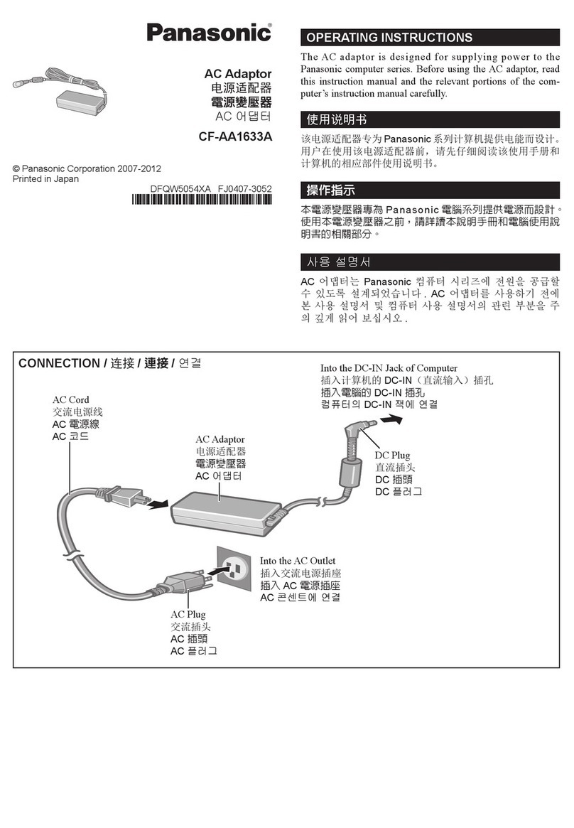
Panasonic CF-AA Series User manual

Panasonic

Panasonic CF-AA Series User manual

Panasonic DM0706SY0 Instruction Manual

Panasonic

Panasonic DM0706SY0 Instruction Manual

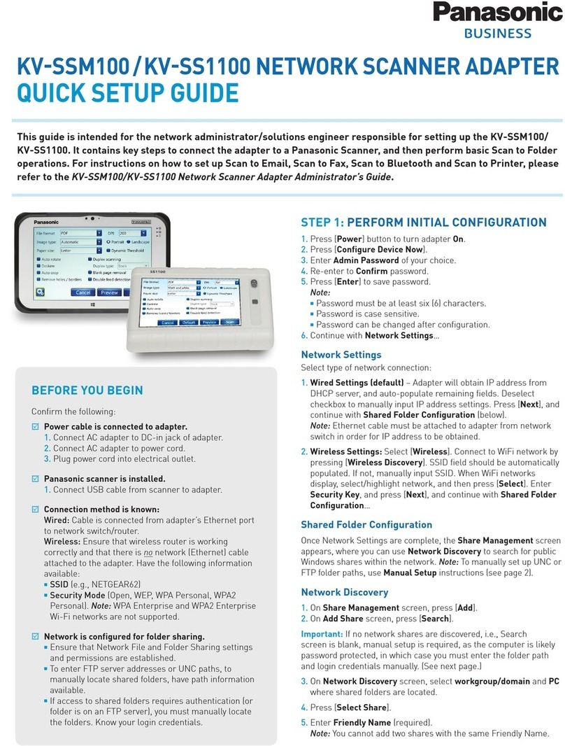
Panasonic KV-SSM100 User manual

Panasonic

Panasonic KV-SSM100 User manual

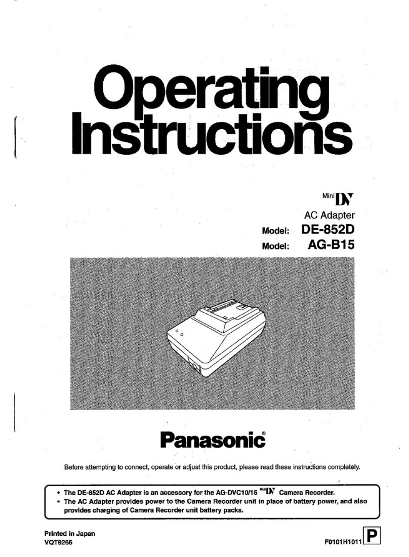
Panasonic DE-852D User manual

Panasonic

Panasonic DE-852D User manual

Panasonic AK-HBA3500G User manual

Panasonic

Panasonic AK-HBA3500G User manual

Panasonic CZ-TACG1 User manual

Panasonic

Panasonic CZ-TACG1 User manual

Panasonic AG-MYA30G - XLR Mic Adaptor User manual

Panasonic

Panasonic AG-MYA30G - XLR Mic Adaptor User manual

Panasonic AWPS505 - AC ADAPTOR User manual

Panasonic

Panasonic AWPS505 - AC ADAPTOR User manual

Panasonic CF-AAV1601AW User manual

Panasonic

Panasonic CF-AAV1601AW User manual

Panasonic ET-WML100U User manual

Panasonic

Panasonic ET-WML100U User manual

Panasonic TY-WL20U User manual

Panasonic

Panasonic TY-WL20U User manual

Panasonic DY-WL5 User manual

Panasonic

Panasonic DY-WL5 User manual

Panasonic CF-AA5713A User manual

Panasonic

Panasonic CF-AA5713A User manual

Panasonic AW-DU600P User manual

Panasonic

Panasonic AW-DU600P User manual

Panasonic BB-HPL11 User manual

Panasonic

Panasonic BB-HPL11 User manual

Panasonic BL-PA300KTA - High Definition Power Line Communication Ethernet Adaptor... User manual

Panasonic

Panasonic BL-PA300KTA - High Definition Power Line Communication Ethernet Adaptor... User manual

Panasonic AG-B15 User manual

Panasonic

Panasonic AG-B15 User manual

Panasonic AW-PS300 User manual

Panasonic

Panasonic AW-PS300 User manual

Panasonic CF-AA6373A User manual

Panasonic

Panasonic CF-AA6373A User manual
Panasonic DY-WL5 User manual

Panasonic

Panasonic DY-WL5 User manual

Panasonic BL-PA100KT User manual

Panasonic

Panasonic BL-PA100KT User manual

Panasonic Palmcorder PV-A18 User manual

Panasonic

Panasonic Palmcorder PV-A18 User manual

Panasonic BB-HCA3A User manual

Panasonic

Panasonic BB-HCA3A User manual

Panasonic AW-PS300 User manual

Panasonic

Panasonic AW-PS300 User manual

Popular Adapter manuals by other brands

Zenisu Keisoku ZS-6822A Series instruction manual

Zenisu Keisoku

Zenisu Keisoku ZS-6822A Series instruction manual

Teknion YEUSB installation guide

Teknion

Teknion YEUSB installation guide

Inateck BR1005 instruction manual

Inateck

Inateck BR1005 instruction manual

Planet VPA-100 Quick installation guide

Planet

Planet VPA-100 Quick installation guide

AirLive WT-2000USB Quick setup guide

AirLive

AirLive WT-2000USB Quick setup guide

Zcom XN-721 user manual

Zcom

Zcom XN-721 user manual

Planet WireFree WL-2400 manual

Planet

Planet WireFree WL-2400 manual

Tripp Lite U209-000-R owner's manual

Tripp Lite

Tripp Lite U209-000-R owner's manual

Planet WL-U356R user manual

Planet

Planet WL-U356R user manual

d & b audiotechnik Z5356 E4 Mounting instructions

d & b audiotechnik

d & b audiotechnik Z5356 E4 Mounting instructions

CoolGear USB-COMi-TB manual

CoolGear

CoolGear USB-COMi-TB manual

Black Box ME890AE-R2 user manual

Black Box

Black Box ME890AE-R2 user manual

Rocket Fish RF-WHD100 Quick setup guide

Rocket Fish

Rocket Fish RF-WHD100 Quick setup guide

Qlogic QLE3142-SR-CK quick start guide

Qlogic

Qlogic QLE3142-SR-CK quick start guide

Tripp Lite P116-000-HDSC1 owner's manual

Tripp Lite

Tripp Lite P116-000-HDSC1 owner's manual

Qlogic FastLinQ 3400 Series user guide

Qlogic

Qlogic FastLinQ 3400 Series user guide

2-Wire PC Port installation guide

2-Wire

2-Wire PC Port installation guide

Blu Stream HD11AU user manual

Blu Stream

Blu Stream HD11AU user manual

manuals.online logo
manuals.online logoBrands
  • About & Mission
  • Contact us
  • Privacy Policy
  • Terms and Conditions

Copyright 2025 Manuals.Online. All Rights Reserved.