Panasonic PAW-160MAH2L User manual

Air Handling Unit Kit 5,00-25,00kW for PACi.
Compatible with R32 or R410A outdoor units
Panasonic AHU Kit, 5,00-25,00kW connected to PACi outdoor unit
The Air Handling Unit Kit has been developed to better meet customer
demand: IP 65 Box in order to be installed outside, 0-10V demand
control* and easy control by BMS
* Only available with PACi Elite, from 5kW to 25kW.
S E T
A L 1
O U T
A T U
P V
S V
ºC
ºC
External BMS
0 – 10V Capacity control
Air Handling Unit (AHU)
PACi or ECOi/ECO G outdoor unit
Demand control on the outdoor unit managed by external 0–10 V signal.
AHU control kit
Main components of mechanical ventilation systems
The main components of a mechanical ventilation system are the
following: Air Handling Unit (AHU), air ducts and air distribution elements.
Exhaust air Outside air
Return air
Supply air
0-10V control
With the 0-10 v demand control the capacity of the outdoor unit can be
controlled by 20 steps.
Input Voltage* (V) 0 1,0 1,5 2,0 2,5 3,0 3,5 4,0 4,5 5,0 5,5 6,0 6,5 7,0 7,5 8,0 8,5 9,0 9,5
Demand (% of
nominal current) No cut 1) 40 45 50 55 60 65 70 75 80 85 90 95 100 105 110 115 120 No limit /
Full capacity 2)
Indoor unit
start / stop Stop 1) Start
1) No cut/Stop: AHU system / indoor unit is completely switched OFF.
2) No Limit: No restrictions applied by BMS to AHU system / indoor unit performance (equivalent to “full-load operation“ of AHU
system / indoor unit).
Control option 1: PAW-280PAH2L
· The system’s control is simple: control of actual suction temperature vs. set point
· Control works in the same way as that of any indoor unit
· Fan signal issued by the PCB (OFF while defrosting, for instance)
Control option 2: PAW-280PAH2
· System control by probe located at air intake. Sensor works as a 0–10V control thermostat which manages the set
point temperature. Control to prevent cold draughts.
· All signals as per standard
Control option 3: PAW-280PAH2
· System control by external environment probe. Sensor works as a 0–10V control thermostat which manages the
set point temperature. Enhances efficiency by adjusting capacity to the ambient temperature and enhances
comfort as well.
· All signals as per standard
Control option 4: PAW-280PAH2
· System control by a 0–10V control working from an external BMS that manages the set point for the temperature or
the capacity. Enhances efficiency by adjusting capacity and enhances comfort as well.
· All signals as per standard
258
03 EU BIGRAC GEN 19.indd 258 5/4/19 9:28

3 types of AHU Kit: Deluxe, Medium and Light.
Model Code IP 65 0-10V demand
control*
Outdoor temperature shift
compensation. Cold draft prevention
PAW-280PAH2 Yes Yes Yes
PAW-280PAH2M Yes Yes No
PAW-280PAH2L Yes No No
* With CZ-CAPBC2.
3
2
1
45
6
7
8
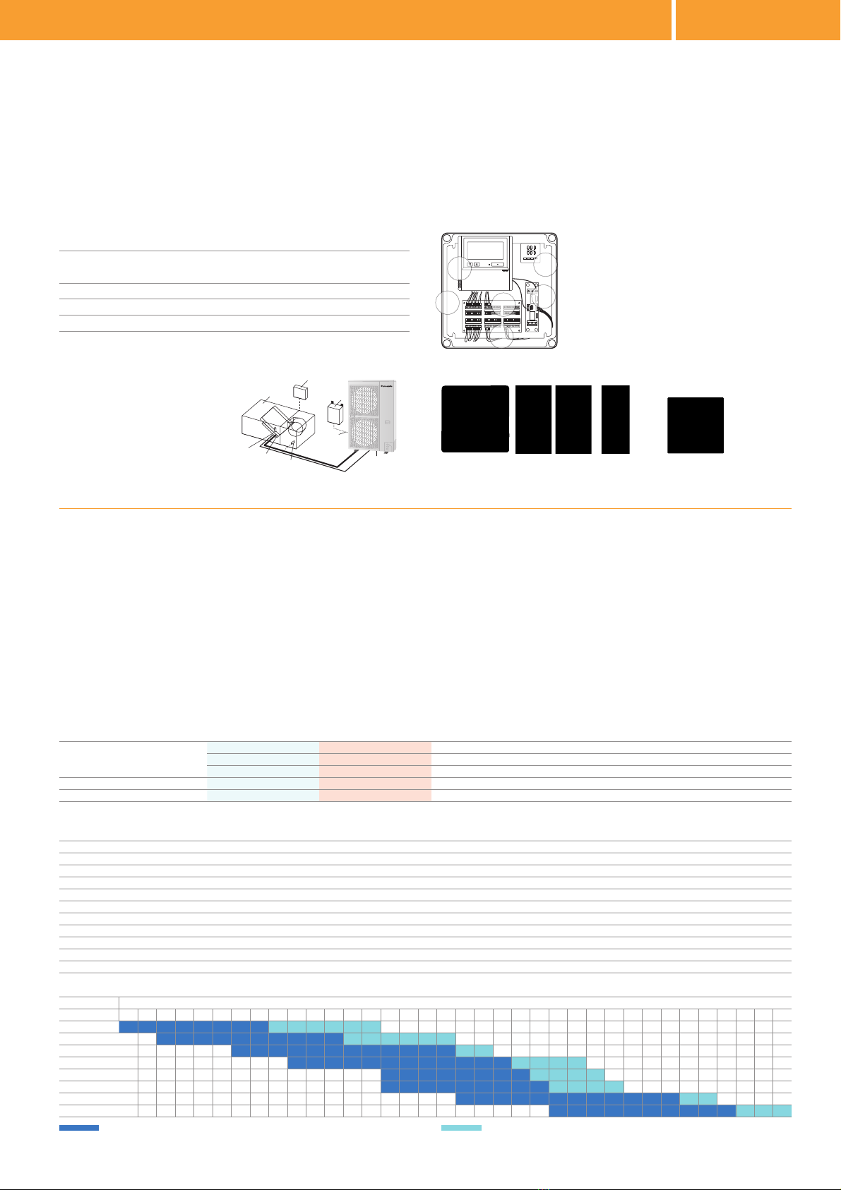
System & regulations. System overview
1. AHU Kit equipment (Field supplied)
2. AHU Kit system controller (Field supplied)
3. AHU Kit controller box (with control PCB)
4. Thermistor for Gas pipe (E2)
5. Thermistor for Liquid pipe (E1)
6. Thermistor for Suction air
7. Inter-unit wiring
8. Outdoor unit
Optional parts: Following functions are available by using different control accessories:
CZ-RTC4 Timer remote controller.
· Operation-ON/OFF
· Mode select
· Temperature setting
* Fan operation signal can be taken from the PCB.
PAW-OCT, DC12 V outlet. OPTION terminal.
· Output signal= Cooling/Heating/Fan status
· Defrost
· Thermostat-ON
CZ-CAPBC2 Mini seri-para I/O unit (advanced version only).
· Easy integration in external AHU control systems and BMS
· Demand control: 40 to 115 % (5 % steps) of nominal current by 0–10 V
input signal*
· Target temperature setting by 0–10 V or 0–140 Ωinput signal*
· Mode select or/and ON/OFF control
· Fan operation control
· Operation status output/ Alarm output
· Thermostat ON/OFF control
* Demand control by external BMS cannot be combined with the demand control or target temperature
setting accomplished by the thermostat. However, if simultaneous demand control and target temperature
setting is needed, this can only be achieved by using a second (optional) CZ-CAPBC2 interface.
CZ-T10 terminal / PAW-T10 PCB to connect to T10 connector.
· A Dry contact PCB has been developed to easily control the unit
· Input signal operation ON/OFF
· Remote control prohibition
· Output signal Operation ON status maximum 230 V 5 A (NO/NC)
· Output signal alarm status max. 230 V 5 A (NO/NC)
· Alarm output (by DC12V)
· Additional available contacts:
- External humidifier control (ON/OFF) 230 VAC 3 A
- External fan control (ON/OFF) 12V DC
- External filter status signal potential free
- External float switch signal potential free
- External leakage detection sensor or TH. OFF contact potential free
(possible usage for external blow out temperature control)
PCB, Power trans,
Terminal block
AHU Connection Kit
Standard wired remote controller.Thermistor x2
(Refrigerant: E1, E2)
Thermistor
(Air: TA; 1 sensor)
1. Remote control CZ-RTC4
2. New plastic IP 65 Box
3. PAW-T10 PCB for Dry Contact
4. 0-10V demand control PCB
5. Intelligent thermostat for:
· Cold draft prevention
· Outdoor temperature shift compensation
6. Terminal base for sensors and power supply
SET
AL1
OUT
ATU
PV
SV
ºC
ºC
Air volume Dimensions Piping length Elevation difference (in/out) Piping connections
AHU connection kit / System combination Min / Max H x W x D Min / Max Max Liquid pipe Gas pipe
Outdoor unit capacity AHU m³/min mm m m Inch (mm) Inch (mm)
5,00kW PAW-280PAH2 8,00 / 13,00 404 x 425 x 78 5 / 30 10 1/4 (6,35) 1/2 (12,70)
6,00kW PAW-280PAH2 9,00 / 16,00 404 x 425 x 78 5 / 30 10 3/8 (9,62) 5/8 (15,88)
7,50kW PAW-280PAH2 12,00 / 25,00 404 x 425 x 78 5 / 30 10 3/8 (9,62) 5/8 (15,88)
10,00kW PAW-280PAH2 14,00 / 33,00 404 x 425 x 78 5 / 30 10 3/8 (9,62) 5/8 (15,88)
12,50kW PAW-280PAH2 19,00 / 35,00 404 x 425 x 78 5 / 30 10 3/8 (9,62) 5/8 (15,88)
14,00kW PAW-280PAH2 19,00 / 35,00 404 x 425 x 78 5 / 30 10 3/8 (9,62) 5/8 (15,88)
20,00kW PAW-280PAH2 28,00 / 66,00 404 x 425 x 78 5 / 70 10 3/8 (9,62) 1 (25,40)
25,00kW PAW-280PAH2 38,00 / 74,00 404 x 425 x 78 5 / 70 10 1/2 (12,70) 1 (25,40)
AHU PACi Elite
Cooling capacity Heating capacity Dimensions Piping length Elevation difference (in/out)
Nominal Nominal H x W x D Min / Max Max
kW kW mm m m
PAW-280PAH2 6,00 / 25,00 7,00 / 28,00 404 x 425 x 78 5 / 30* 10
PAW-280PAH2+PAW-280PAH2 50,00 56,00 404 x 425 x 78 5 / 30* 10
* For U-200PE2E8A and U-250PE2E8A.
Air flow rate m³/min
Outdoor unit 8,00 8,33 9,00 10,00 10,83 11,67 12,00 13,00 13,33 14,00 15,00 16,00 16,67 18,00 19,00 20,00 25,00 26,67 28,00 30,00 33,00 35,00 36,00 38,00 40,00 43,33 45,00 50,00 58,33 66,00 66,67 71,67 74,00 75,00 83,33 90,00
5,00kW
6,00kW
7,50kW
10,00kW
12,50kW
14,00kW
20,00kW
25,00kW
Standard range of air flow rate under standard conditions (air intake temperature in cooling mode from 18 to 32°C DB). Extended range of air flow rate under special conditions (air intake temperature in cooling mode from 18 to 30°C DB).
1
4
2
5
3
6
AHU Kit connects PACi outdoor units to Air Handling Units system.
The Panasonic AHU Kits offer a wealth of connectivity possibilities so can
be easily integrated into many systems.
Application: Hotels, offices, server rooms or all large buildings where air
quality control such as humidity control and fresh air and is needed.
259
NEW —COMMERCIAL
03 EU BIGRAC GEN 19.indd 259 5/4/19 9:28

Air Handling Unit Kit
Installation Instructions
SET
AL1
OUT
ATU
PV
SV
ºC
ºC


3
Air Handling Unit Kit
Installation Instructions
Original Installation Instructions (English)
July 2019
COPYRIGHT
© Panasonic Marketing Europe GmbH 2019. All rights reserved.
.

4
Table of Contents
1 General information and safety instructions .................................................... 6
1.1 Introduction ......................................................................................................................... 6
1.2 Structure and meaning of notices and symbols.............................................................. 7
1.3 Safety instructions.............................................................................................................. 8
1.4 Instructions for the safe handling of R32 ......................................................................... 9
1.4.1 Calculating the density limit ........................................................................................ 10
1.4.2 Preventing leakages ................................................................................................... 14
1.4.3 Detecting leaks ........................................................................................................... 15
1.4.4 Repairing leaks ........................................................................................................... 15
1.5 Warranty policy ................................................................................................................... 15
2 Ventilation theory and air handling units .......................................................... 16
2.1 Purpose of air-conditioning ............................................................................................... 16
2.2 Mechanical ventilation systems ........................................................................................ 17
2.3 Air handling units................................................................................................................ 17
3 Product description ............................................................................................. 20
3.1 General description ............................................................................................................ 20
3.2 Scope of supply .................................................................................................................. 21
3.3 System lineup...................................................................................................................... 26
3.4 System Overview ................................................................................................................ 28
3.5 Technical data ..................................................................................................................... 32
4 Installation ............................................................................................................ 40
4.1 Installation of AHU Kit ........................................................................................................ 40
4.2 Installation of refrigerant piping........................................................................................ 43
4.3 Installation of expansion valve.......................................................................................... 43
4.4 Installation of thermistors.................................................................................................. 45
4.4.1 Installation of thermistor on gas pipe .......................................................................... 46
4.4.2 Installation of thermistor on liquid pipe........................................................................ 47
4.4.3 Installation of thermistor on heat exchanger pipe middle ........................................... 48
4.4.4 Installation of thermistor for suction and discharge air stream.................................... 49
4.5 Matching outdoor unit capacity with AHU Kit capacity................................................... 49
5 Electrical Wiring................................................................................................... 55
5.1 General precautions on wiring .......................................................................................... 55
5.2 Recommended wire lengths and diameters..................................................................... 56
5.3 Connection of wiring to terminals..................................................................................... 56
5.4 Terminal board layout......................................................................................................... 58

5
5.5 Wiring layout ....................................................................................................................... 64
5.6 Wiring system diagrams..................................................................................................... 76
5.7 Connection of external signal lines................................................................................... 79
6 Test Run ................................................................................................................ 84
7 Control .................................................................................................................. 85
7.1 Remote controller ............................................................................................................... 85
7.2 Thermostat........................................................................................................................... 85
7.2.1 Control and display elements...................................................................................... 85
7.2.2 Operation .................................................................................................................... 85
7.2.3 Initial Settings.............................................................................................................. 91
7.2.4 Error Codes................................................................................................................. 96
7.2.5 Maintenance and Service ........................................................................................... 96

6
General information and safety instructions
1 General information and safety instructions
1.1 Introduction
This document contains the installation instructions for the Panasonic AHU Kits.
AHU Kits connect Panasonic ECOi, ECO G and PACi outdoor units to third-party air handling
unit systems, using the same refrigerant circuit as the VRF system.
While ECOi and ECO G systems exclusivly use R410A as refrigerant, some PACi systems are
operated with R410A while others are operated with the new refrigerant R32.
Application examples for Panasonic AHU Kits are hotels, offi ces, server rooms or all large build-
ings where air quality control such as humidity control and fresh air is needed.
Where information in this document does not apply to all three VRF system ranges, but only to
either ECOi, ECO G or PACi systems, this will be indicated by the relevant product range logos:
The AHU Kits are supplied in three diff erent product versions, “light”, “medium” or “advanced”,
and can be selected based on the required functionality. The following products are covered in
this documentation:
Product version
Light
PAW-160MAH2L
PAW-280MAH2L PAW-280PAH2L
PAW-560MAH2L
Medium
PAW-160MAH2M
PAW-280MAH2M PAW-280PAH2M
PAW-560MAH2M
Advanced
PAW-160MAH2
PAW-280MAH2 PAW-280PAH2
PAW-560MAH2
The installation should be performed only by qualifi ed electricians in strict accordance with the
installation instructions and especially with the safety instructions given in this document.
The appliance is not to be used by persons (including children) with reduced physical, sensory
or mental capabilities, or lack of experience and knowledge, unless they have been given super-
vision or instruction. Children being supervised are not to play with the appliance.
Important: Validity of this document
Due to the ongoing development and innovation of Panasonic products, this document and all
the information contained herein may not refl ect the current status of the relevant products. Pre-
liminary or missing information will be updated and added on an ongoing basis and published at
the discretion of Panasonic.
i

7
General information and safety instructions
1.2 Structure and meaning of notices and symbols
Safety notices
WARNING
This indicates a hazardous situation which, if not avoided, could result in death or serious injury.
CAUTION
This indicates a hazardous situation which, if not avoided, could result in minor or moderate
injury.
NOTICE
This indicates a hazardous situation which, if not avoided, could result in property damage.
Other notices
Important
This indicates other important information or references to other useful sources of technical data
and descriptions.
!
i

8
General information and safety instructions
1.3 Safety instructions
WARNING
The following precautions need to be followed strictly, in order to avoid hazardous situations,
which could result in death or serious injury.
Electric shock or fi re may result from inadequate or incorrect installation or wiring
procedures.
► System installation must only be performed by an experienced electrician.
►Arrange installation at the dealer where the system was purchased or use a professio-
nal installer.
► System installation must be performed in strict accordance to the installation procedu-
res described in this document.
Damage to the circuit breakers may result from incorrect electrical wiring, insuffi cient
electrical circuit capacity or use with other electrical devices.
► Always use a dedicated branch circuit for electrical wiring.
►Strictly avoid using other electrical devices within the same electrical circuit.
► Make sure the electrical circuit used has suffi cient capacity.
Overheating or fi re may result if connections or attachments are not secure.
► Use the specifi ed cables (type and wiring diameter) for the electrical connections, and
securely connect the cables.
► Run and fasten the cables securely so that external forces or pressure placed on the
cables will not be transmitted to the connection terminals.
Suff ocation can result if refrigerant gas leaks and exceeds the limit density in a small
room.
► Installation of the refrigerant piping must only be performed by an experienced, quali-
fi ed installer to minimize the risk of leaks.
►Install so that even if refrigerant gas leaks into the instalation space, it will not exceed
the practical limit density of 0.44 kg/m3for R410A and 0.061 kg/m3for R32, in ac-
cordance with the local regulations for facility air conditioning equipment. However, for
further limits and calculations to be done, see →1.4 Instructions for safe handling of
R32
►If the refrigerant gas concentration does exceed the density limit, do one of the
following:
● install an opening in a neighbouring room
● or install ventilation equipment triggered by gas leak detection sensors
● or install an automatic pump-down system provided by the manufacturer of
the equipment
Poisonous gas can result if refrigerant gas comes into contact with fi re.
►After installation of refrigerant pipes, perform a dry nitrogen gas sealing test to check
that there are no leaks.
►Ventilate the work area if refrigerant gas leaks during installation.
►Prevent the refrigerant gas from coming into contact with a fan heater, stove, range, or

9
General information and safety instructions
other source of fi re.
Incorrect installation can result in falling equipment causing damage, injuries or other
accidents.
►Install in a location that is fully strong enough to support the weight of the equipment.
►Perform installation that is secure enough to withstand earthquakes, whirlwinds,
storms and other strong winds.
Frostbite injuries may result from coming into direct contact with the refrigerant gas.
► When handling refrigerant gas, be careful not to touch the refrigerant gas directly.
CAUTION
The following precautions need to be followed strictly, in order to avoid hazardous situations,
which could result in minor or moderate injury.
Electric shock, shock and fi res may result from incomplete grounding of the equipment
or failure to install an earth leakage circuit breaker (ELCB) or residual Current Device
(RCD).
►Be sure to ground equipment properly.
►Do not attach ground wires to gas pipes, water pipes, lightning arresters, or telephone
ground lines.
► Always install an earth leakage circuit breaker or residual current device.
Ignition of fl ammable gas or infl ammable materials may result from installing the system
in locations where fl ammable gas can generate, enter, build up, or leak.
► Do not install the system in locations where fl ammable gas can occur in any way.
► Do not install in locations where volatile infl ammable materials are handled.
1.4 Instructions for the safe handling of R32
As R32 is a fl ammable refrigerant, additional precautions, installation and handling instructions
need to be observed.

10
General information and safety instructions
WARNING
The following precautions need to be followed strictly, in order to avoid hazardous situations,
which could result in death or serious injury.
A fi re or explosion hazard and the generation of poisonous gas may result if R32 refrige-
rant gas comes into contact with open fl ames.
► The air conditioning appliance with direct expansion (DX) coil shall be installed, ope-
rated and stored in a space without continuously operating ignition sources (e.g. open
fl ames, an operating gas appliance or an operating electric heater).
► If DX coil appliance is not installed in a separate refrigeration machinery room as spe-
cifi ed in EN378, calculate the maximum allowed density limit of the relevant installati-
on space as detailed below (see → 1.4.1 Calculating the density limit).
► The DX coil appliance shall be installed, operated and stored in a well ventilated space
with a ceiling height of at least 2.5 m and a fl oor area larger than [Amin] m2so that it
complies with the required density limit (see → 1.4.1 Calculating the density limit).
►Pay particular attention to prevent refrigerant leakages during installation, mainte-
nance and repair work (see → 1.4.2 Preventing leaks).
► If a leak is suspected, do the following:
»remove or extinguish all naked fl ames immediately
»ventilate the room immediately
»use a calibrated electronic leak dectector to detect any leaks (see
→ 1.4.3 Detecting leaks)
► Repair any leaks diligently (see → 1.4.4 Repairing leaks), before refi lling the refrige-
rant cycle with refrigerant and checking for any leaks again.
NOTICE
For full details on the required precautions for the installation and maintenance of an R32 unit,
always refer to the Installation Guide of the relevant PACi unit.
1.4.1 Calculating the density limit
As R32 is a slightly fl ammable refrigerant (ASHRAE fl ammability class A2L), the requirements
for the installation space of the DX coil appliance must comply with the applicable regulations
and standards, such as EN60335-2-40 and EN378.
Depending on perspective, the density limit determines either the minimum fl oor area “Amin”
(specifi ed in m2) required for a given refrigerant charge amount (specifi ed in kg), or vice versa
the allowed maximum refrigerant charge “mmax” for the DX coil appliance (specifi ed in kg) in
relation to the fl oor area of the available installation space (specifi ed in m2). The charge limits for
R32 installations (based on EN60335-2-40, 5th edition) also depend on the mounting position of
the DX coil.
!

11
General information and safety instructions
While there are no fl oor area limitations for refrigerant charges of less than 1.23 kg, the mini-
mum fl oor area [Amin] for larger refrigerant charge amounts can be calculated by the following
formula:
0.0 50.0 100.0 150.0 200.0 250.0
Floor area (m2)
ceiling-mounted
wall-mounted
floor-mounted
0.0
1.0
2.0
3.0
4.0
5.0
6.0
7.0
8.0
Allowed R32 refrigerant charge (kg)
Amin = [mc]2
2.5 x LFL5/4 x h0
Amin=minimum fl oor area (m2)
mc=refrigerant charge (kg)
h0=height factor (mounting position):
– 0.6 for fl oor-mounted
– 1.8 for wall-mounted
– 1.0 for window-mounted
– 2.2 for ceiling mounted
LFL= R32 Lower Flammability Limit
(0.307 kg/m3)
Calculating examples
Using the above formula, it is possible to calculate
a) the minimum fl oor area for a given refrigerant charge, or
b) the maximum refrigerant charge allowed for a given fl oor area.
Example:
S-36PF1E5B + U-36PZH2E5
3.6 kW, 7 m piping length
1,15 kg refrigerant charge
a) A given refrigerant charge amount of 1.15 kg
requires a minimum fl oor area of 0.84 m2.
b) For a given fl oor area of 10 m2the maximum
refrigerant charge amount is 3.97 kg.
Refrigerant charge:
1,15 kg
2.5 m
10,0 m2
2.2 m
Density limit diagrams
The following diagrams roughly demonstrate the relation between the installation space fl oor
area and the amount of refrigerant charged for the relevant R32 PACi outdoor units, provided

12
General information and safety instructions
the DX coil appliance is installed in an occupied area under the ceiling or in an equivalent
position.
[mc] Refrigerant charge amount (i.e. total of refrigerant at shipment and refrigerant charge
amount in the fi eld), specifi ed in kg
[mmax]Maximum refrigerant charge amount, specifi ed in kg
[mc] ≤ 1.22 Can be installed
1.22 < [mc] ≤ [mmax] Installation possible within the hatched range
[mc] > [mmax] Can not be installed
U-60PZ2E5, U-71PZ2E5, U-36PZH2E5, U-50PZH2E5, U-60PZH2E5
10.0
8.0
6.0
4.0
2.0
0.0
[Amin]: minimum indoor floor area (m2)
[mc]: refrigerant charge (kg)
of the outdoor unit
* U-36PZH2E5, U-50PZH2E5
Can not be installed
Can be installed
Can not be installed
0.0 0.5 1.0
1.22 1.35 1.80
1.5 2.0 2.5
Standard Elite
U-60PZ2E5
U-71PZ2E5
U-36PZH2E5
U-50PZH2E5
U-60PZH2E5
[mmax] (kg) 1.80 1.35 1.80

13
General information and safety instructions
U-71PZH2E5, U-71PZH2E8, U-100PZH2E5, U-100PZH2E8, U-125PZH2E5, U-125PZH2E8,
U-140PZH2E5, U-140PZH2E8
0.0
2.0
4.0
6.0
8.0
10.0
12.0
14.0
16.0
18.0
20.0
22.0
24.0
26.0
6.56.05.55.04.54.03.53.02.52.01.51.00.50.0
[Amin]: minimum indoor floor area (m2)
[mc]: refrigerant charge (kg)
of the outdoor unit
Can be
installed
* U-71PZH2E5, U-71PZH2E8
Can not be installed
Can not be
installed
1.220 2.850 5.975
Elite
U-71PZH2E5
U-71PZH2E8
U-100PZH2E5
U-100PZH2E8
U-125PZH2E5
U-125PZH2E8
U-140PZH2E5
U-140PZH2E8
[mmax] (kg) 2.850 5.975
U-100PZ2E5, U-100PZ2E8, U-125PZ2E5, U-125PZ2E8, U-140PZ2E5, U-140PZ2E8
0.0
2.0
4.0
6.0
8.0
10.0
12.0
14.0
16.0
18.0
20.0
5.04.54.03.53.02.52.01.51.00.50.0
[Amin]: minimum indoor floor area (m2)
[mc]: refrigerant charge (kg)
of the outdoor unit
* U-100PZ2E5, U-100PZ2E8
Can not be installed
Can be installed
Can not be installed
1.22 3.50 3.88
Standard
U-100PZ2E5
U-100PZ2E8
U-125PZ2E5
U-125PZ2E8
U-140PZ2E5
U-140PZ2E8
[mmax] (kg) 3.50 3.88

14
General information and safety instructions
U-200PZH2E8, U-250PZH2E8
6.5 7.0 7.5 8.0 8.56.05.55.04.54.03.53.02.52.01.51.0
1.22 7.80
0.50.0
[mc]: refrigerant charge (kg) of the outdoor unit
Can be installed
Can not be installed
45.0
20.0
25.0
30.0
35.0
40.0
15.0
10.0
5.0
0.0
[Amin]: minimum indoor floor area (m2)
Elite
U-200PZH2E8 U-250PZH2E8
[mmax] (kg) 7.80
1.4.2 Preventing leakages
● Do not let air enter the refrigeration cycle, because this will increase the risk of
explosion and injury due to high tension inside the refrigerant cycle.
● Keep all tubing runs as short as possible.
● Use the fl are method for connecting tubing and apply refrigerant lubricant to the
matching surfaces of the fl are and union tubes before connecting them, then tigh-
ten the nut with a torque wrench for a leak-free connection.
● Do not leak refrigerant while working on the refrigerant tubes during installation,
maintenance or repair.
● Check carefully for leaks (see → 1.4.3 Detecting leaks) before starting the test run.

15
General information and safety instructions
1.4.3 Detecting leaks
● If a leak is suspected, remove or extinguish all naked fl ames and ventilate the
space immediately.
●To search for and detect any refrigerant leaks, never use potential sources of igniti-
on like e.g. a halide torch or any other detector using a naked fl ame.
● Leak detection fl uids are suitable for use with most refrigerants, but the use of
detergents containing chlorine shall be avoided, as the chlorine may react with the
refrigerant and corrode the copper pipework.
● Preferably, use an electronic leak dectector, which is suitable for R32, to check for
leaks.
●Make sure that the electronic detector has an adequate sensitivity and that it has
been calibrated in a refi rgerant-free area.
● Set the leak detector to a percentage of the lower fl ammable limit (LFL) of the rele-
vant refrigerant, and calibrate the detector to the refrigerant used (R32) so that the
appropriate percentage of refrigerant gas (max. 25 %) is confi rmed.
1.4.4 Repairing leaks
If a leakage of refrigerant is found, which requires brazing, do the following:
● Recover all refrigerant from the system, or isolate all refrigerant by means of shut-
off valves in a part of the system remote from the leak.
● Purge the system with oxygen-free nitrogen (OFN) both, before and during the
brazing process.
● Re-fi ll the system with refrigerant and check for any remaining leaks (see
→ 1.4.3 Detecting leaks).
●Repeat this procedure until no more leaks are detected.
1.5 Warranty policy
We can be held responsible for the quality and performance of the AHU Kit we supply.
However, we cannot be held responsible for the performances, operations and machine controls
of your complete AHU system which incorporates our AHU Kit, nor for the components used in
the refrigerant cycle of your AHU system (including, but not limited to, compressors, high-pres-
sure switches, check valves, strainers, expansion valves, solenoid valves, 4-way valves, capil-
lary tubes, accumulator tanks, and heat exchanger tubes), nor for any damages and defects
caused in the process of installing our AHU Kit, by the system design and/or during assembly of
your AHU system.
We do not publish the certifi cate to show conformity to the EMC and the product safety require-
ments applicable to your complete AHU system.

16
Ventilation theory and air handling units
2 Ventilation theory and air handling units
2.1 Purpose of air-conditioning
The purpose of air-conditioning is to provide comfortable indoor air conditions for the room oc-
cupants and to provide energy saving potentials for the owner.
Comfort
If room occupants feel “comfortable“ in a given room, depends mainly on the following two
factors:
●air temperature
●relative air humidity
However, optimum working or living conditions do not only exist at a specifi c setpoint of room
temperature and room humidity, but also within a certain band width of the setpoint.
A temperature setpoint of 22 °C and a relative humidity setpoint of 45 % with variations of ±2 °C
and ±15 %rh respectively are typical levels used for offi ce spaces. Also, at high temperatures,
maximum limitation of absolute humidity should be provided to avoid “muggy” conditions. Typi-
cally, this limit value lies at about 10 g/kg (H2O).
Absolute humidity
rh = relative humidity
Temperature
Cooling and
humdifying
Heating and
humdifying
Humdifying and
reheating, if required
Humdifying only Comfort range
35 %rh
24 °C
20 °C
65 %rh
Cooling only
Heating only
Energy savings
Besides the advantages in terms of indoor air quality, air conditioning off ers also an energy sav-
ing potential. For example, while uncontrolled ventilation through open windows leads to large
amounts of heat being lost to the outside during the heating season or gained from the outside
during the cooling season, air conditioning systems provide possibilities to utilize the extra “free”
energy in heat recovery modules so that overall operating costs will be reduced.
The larger the area of the comfort range, the better the energy saving opportunities.

17
Ventilation theory and air handling units
2.2 Mechanical ventilation systems
Main components of mechanical ventilation systems
The main components of a mechanical ventilation system are the following:
● Air handling unit (AHU)
●Air ducts
● Air distribution elements
Supply air
Outside air
Return air
Exhaust air
2.3 Air handling units
Main components of air handling units
The main components of an air handling unit are shown in the following graphic.
Mixed air (MA)
Supply air fan
(SAF)
Supply air
(SA)
Outside air
(OA)
Return air
(RA)
Exhaust air
(EA)
Dampers
(D)
Dampers
(D)
Dampers
(D)
Cooling Coil
(CC)
Heating Coil
(HC)
Air handling unit (AHU)
Filter
(F)
Recirculated
air (CA)

18
Ventilation theory and air handling units
Main types of air handling units
Supply type
Exhaust type
Supply/Exhaust type with cross-fl ow heat exchanger
Supply/Exhaust type with mixing chamber
Other manuals for PAW-160MAH2L
2
This manual suits for next models
11
Table of contents
Other Panasonic Air Handler manuals
Popular Air Handler manuals by other brands

System air
System air SAVE VTR 150/B user manual

Water Furnace
Water Furnace TruClimate 500 installation guide

System air
System air Geniox 10 user manual

System air
System air SAVE VSC 200 user manual

System air
System air SUE 250EC Installation and operating instructions

Blue Ridge
Blue Ridge KIT-BPK12 instruction manual

Dantherm
Dantherm Sovelor D3i User and Maintenance Book

McQuay
McQuay Vision CA Series Installation and maintenance manual

BLAUBERG
BLAUBERG VUT 270 V5B EC user manual

Pioneer
Pioneer WYS Series Disassembly guide

AAON
AAON RZ Series Installation operation & maintenance

Euroclima
Euroclima ZHK NANO instruction manual