manuals.online logo
Brands
  1. Home
  2. •
  3. Brands
  4. •
  5. Panasonic
  6. •
  7. Air Handler
  8. •
  9. Panasonic PAW-160MAH2L User manual

Panasonic PAW-160MAH2L User manual

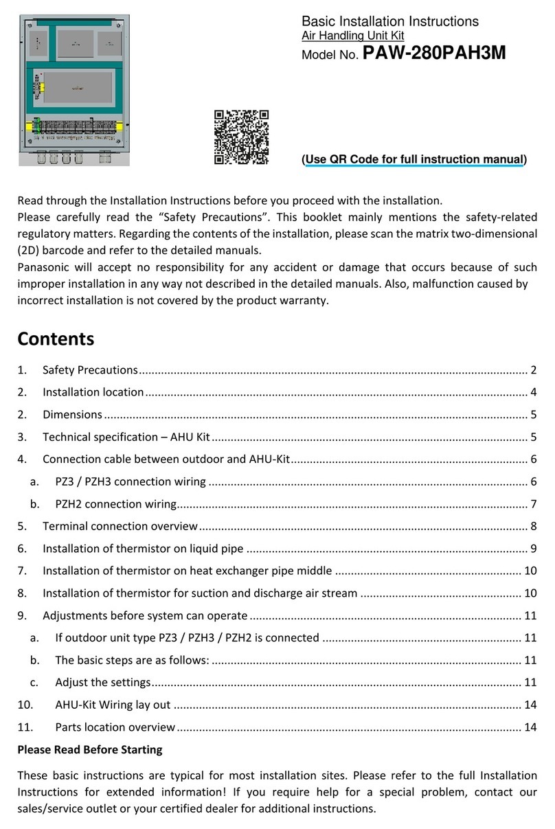
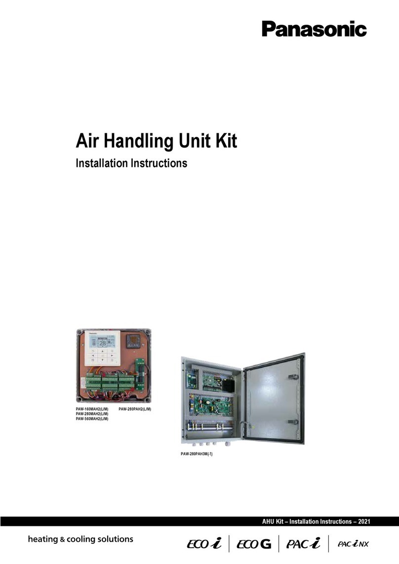
Air Handling Unit Kit
Installation Instructions




















3
Air Handling Unit Kit
Installation Instructions
Original Installation Instructions (English)
February 2016
COPYRIGHT
© Panasonic Marketing Europe GmbH 2016.All rights reserved.
.
4
Table of contents
1
General information and safety instructions
....................................................
6
1.1
Introduction
.........................................................................................................................
6
1.2
Structure and meaning of notices and symbols
..............................................................
7
1.3
Safety instructions
..............................................................................................................
8
1.4
Warranty policy
...................................................................................................................
9
2
Ventilation theory and air handling units
..........................................................
10
2.1
Purpose of air-conditioning
...............................................................................................
10
2.2
Mechanical ventilation systems
........................................................................................
11
2.3
Air handling units
................................................................................................................
11
3
Product description
.............................................................................................
14
3.1
General description
............................................................................................................
14
3.2
Scope of supply
..................................................................................................................
15
3.3
System lineup
......................................................................................................................
20
3.4
System Overview
................................................................................................................
22
3.5
Technical data
.....................................................................................................................
26
4
Installation
............................................................................................................
32
4.1
Installation of AHU
Kit
........................................................................................................
32
4.2
Installation of refrigerant piping
........................................................................................
35
4.3
Installation of expansion valve
..........................................................................................
35
4.4
Installation of thermistors
..................................................................................................
37
4.4.1
Installation of thermistor on gas pipe
........................................................................
38
4.4.2
Installation of thermistor on liquid pipe
.....................................................................
39
4.4.3
Installation of thermistor on heat exchanger pipe middle
.........................................
40
4.4.4
Installation of thermistor for suction and discharge air stream
.................................
41
4.5
Matching outdoor unit capacity with AHU
Kit capacity
...................................................
41
5
Electrical Wiring
...................................................................................................
45
5.1
General precautions on wiring
..........................................................................................
45
5.2
Recommended wire lengths and diameters
.....................................................................
46
5.3
Connection of wiring to terminals
.....................................................................................
46
5.4
Terminal board layout
.........................................................................................................
48
5.5
Wiring layout
.......................................................................................................................
52
5.6
Wiring system diagrams
.....................................................................................................
60
5.7
Connection of external signal lines
...................................................................................
63
6
Test Run
................................................................................................................
68
5
7
Control
..................................................................................................................
69
7.1
Remote controller
...............................................................................................................
69
7.2
Thermostat
...........................................................................................................................
69
7.2.1
Control and display elements
...................................................................................
69
7.2.2
Operation
..................................................................................................................
70
7.2.3
Initial Settings
...........................................................................................................
75
7.2.4
Error Codes
..............................................................................................................
80
7.2.5
Maintenance and Service
.........................................................................................
80
6
General information and safety instructions
1
General information and safety instructions
1.1
Introduction
This document contains the installation instructions for the PanasonicAHU
Kits.
AHU
Kits connect Panasonic ECOi, ECO
G and PACi outdoor units to third-party air handling
unit systems, using the same refrigerant circuit as the VRF system.
-
ings where air quality control such as humidity control and fresh air is needed.
The AHU
Kits are supplied in three different product versions, “light”, “medium” or “advanced”,
Product version
Light
PAW-160MAH2L
PAW-280MAH2L
PAW-280PAH2L
PAW-560MAH2L
Medium
PAW-160MAH2M
PAW-280MAH2M
PAW-280PAH2M
PAW-560MAH2M
Advanced
PAW-160MAH2
PAW-280MAH2
PAW-280PAH2
PAW-560MAH2
installation instructions and especially with the safety instructions given in this document.
-
Due to the ongoing development and innovation of Panasonic products, this document and
i
7
General information and safety instructions
1.2
Structure and meaning of notices and symbols
Safety notices
WARNING
This indicates a hazardous situation which, if not avoided, could result in death or serious injury.
CAUTION
This indicates a hazardous situation which, if not avoided, could result in minor or moderate
injury.
NOTICE
This indicates a hazardous situation which, if not avoided, could result in property damage.
Other notices
Important
This indicates other important information or references to other useful sources of technical data
and descriptions.
!
i
8
General information and safety instructions
1.3
Safety instructions
WARNING
which could result in death or serious injury.
procedures.
Arrange installation at the dealer where the system was purchased or use a
professional installer.
electrical circuit capacity or use with other electrical devices.
Strictly avoid using other electrical devices within the same electrical circuit.
-
Suffocation can result if refrigerant gas leaks and exceeds the limit density in a small
room.
3
, in accordance with the local regulatioins for facility
air conditioning equipment.
If the refrigerant gas concentration does exceed the limit density, do one of the
the equipment
After installation of refrigerant pipes, perform a dry nitrogen gas sealing test to
9
General information and safety instructions
Prevent the refrigerant gas from coming into contact with a fan heater, stove,
accidents.
Install in a location that is fully strong enough to support the weight of the
equipment.
storms and other strong winds.
directly.
CAUTION
which could result in minor or moderate injury.
or failure to install an earth leakage breaker.
Be sure to ground equipment properly.
Do not attach ground wires to gas pipes, water pipes, lightning arresters, or
telephone ground lines.
way.
1.4
Warranty policy
of your complete AHU system which incorporates our AHU
Kit, nor for the components used in
-
-
your AHU system.
-
10
Ventilation theory and air handling units
2
Ventilation theory and air handling units
2.1
Purpose of air-conditioning
-
cupants and to provide energy saving potentials for the owner.
Comfort
air temperature
relative air humidity
A temperature setpoint of 22
°C and a relative humidity setpoint of 45
% with variations of ±2
°C
-
2
Absolute humidity
rh = relative humidity
Cooling and
humdifying
Heating and
humdifying
Humdifying and
reheating, if required
Humdifying only
Comfort range
35
%rh
24
°C
20
°C
65
%rh
Cooling only
Heating only
Energy savings
Besides the advantages in terms of indoor air quality, air conditioning offers also an energy sav
-
ing potential. For example, while uncontrolled ventilation through open windows leads to large
11
Ventilation theory and air handling units
2.2
Mechanical ventilation systems
Main components of mechanical ventilation systems
Air ducts
Outside air
Return air
Exhaust air
2.3
Air handling units
Main components of air handling units
The main components of an air handling unit are shown in the following graphic.
Mixed air (MA)
Supply air fan
(SAF)
Supply air
(SA)
Outsideair
(OA)
Returnair
(RA)
Exhaust air
(EA)
Dampers
(D)
Cooling Coil
(CC)
HeatingCoil
(HC)
Air handling unit (AHU)
Filter
(F)
12
Ventilation theory and air handling units
Main types of air handling units
Supply type
Exhaust type
13
Ventilation theory and air handling units
Supply exhaust type with rotary heat exchanger
Connecting AHU systems via the AHU
Kit to ECOi/ECO
G or PACi outdoor
units
The following graphic shows an example for connecting a third-party air handling unit via the
Demand control on the outdoor unit manged by external 0–10
V signal
PACi or ECOi/ECO
G outdoor unit
Air Handling Unit Kit
External control
system
Air Handling Unit
1
Capacity control through external BMS via 0–10
V signal
2
-
trol, this schematic layout does not apply to the “light” AHU
Kit version.
14
Product description
3
Product description
3.1
General description
integrated into many systems.
Version
Light
Medium
Advanced
Connectable with P-LINK system.
X
X
X
Fancontrol signalfrom the PCB canbe usedfor controlling the air
volume of an external fan (High/Mid/Low and LL for Th-OFF)
X
X
X
Defrost operation signal, Thermo-ON/OFF states output
X
X
X
Drain pump control
X
X
X
X
X
X
Alarm and operation output
X
X
X
The system is controlled by the air intake (or room return air) tempera
-
ture in the same way as a standard indoor unit. Selectable modes:
Automatic / Cooling / Heating / Fan/ Dry (equivalent to Cooling).
X
X
X
Easy integration into BMS orAHU control systems using demand con
-
trol:40 to 115
% (5
% steps) of nominal current by 0–10
V input signal
–
X
X
Temperature set point adjustment by external control system using
0–10
V or 0–140
Ohm signal
–
X
X
Room supply air temperature can becontrolled by theadditionalther
-
mostat, its supply air temperature sensor and the 0–10
V input signal for
–
–
X
Target temperature setting based on ambient temperature with
CZ-CAPBC2 interface using 0–10
V signal
–
–
X
15
Product description
3.2
Scope of supply
-
different scopes of supply.
Scope of supply
Version
Light
Medium
Advanced
PAW-160MAH2L
PAW-160MAH2M
PAW-160MAH2
PAW-280MAH2L
PAW-280PAH2L
PAW-280MAH2M
PAW-280PAH2M
PAW-280MAH2
PAW-280PAH2
PAW-560MAH2L
PAW-560MAH2M
PAW-560MAH2
IP65 case
X
X
X
X
X
X
Control unit including transformer
X
X
X
X
X
X
Relays
X
X
X
X
X
X
Terminal boards
X
X
X
X
X
X
Remote controller (CZ-RTC2 / CZ-RTC4*)
X
X
X
X
X
X
PCB for T10 connection (PAW-T10)
X
X
–
–
X
X
Expansion valve
X
–
X
–
X
–
PCBs for the expansion and RAP / SVK valves
X
–
X
–
X
–
Refrigerant temperature sensors
E1 + E3
X
–
X
–
X
–
E1 + E2
–
X
–
X
–
X
Air intake and air outlet temperature
sensors
TA
X
X
X
X
X
X
BL
X
–
X
–
X
–
CZ-CAPBC2 interface for 0-10 V control
(ACC-SP1A)
–
–
X
X
X
X
Thermostat (TR-16 / TR-17*) including an ad
-
ditional temperature sensor to be used either for
room supply air or ambient air temperature
–
–
–
–
X
X
Depending on AHU
Kit generation.
Exterior view of AHU
Kits and some of their compoments
Thermistor x2
(Refrigerant: E1, E2)
Thermistor
(Air: TA)
PACi accessories
Light version: PAW-280PAH2L*
1
Remote controller (CZ-RTC2 / CZ-RTC4)
2
External signal control PCB(PAW-T10)
3
Terminal board with 6
connectors
* Shown as an example and with transparent front cover removed.
1
3
2
16
Product description
Thermistor x2
(Refrigerant: E1, E2)
Thermistor
(Air: TA)
PACi accessories
Medium version: PAW-280PAH2M*
1
Remote controller (CZ-RTC2 / CZ-RTC4)
2
Terminal board with 6
connectors
3
CZ-CAPBC2 interface (on rear side)
* Shown as an example and with transparent front cover removed.
1
2
3
ECOi / ECO
G accessories
Expansion
valve
Thermistor x2
(Refrigerant: E1, E3)
Thermistor x2
(Air: TA, BL)
Advanced version: PAW-560MAH2*
1
Remote controller (CZ-RTC2 / CZ-RTC4)
2
Thermostat (TR-16/TR-17)
3
External signal control PCB(PAW-T10)
4
Terminal board with 6
connectors
5
CZ-CAPBC2 interface (on rear side)
*AHU
Kit shown withtransparent front cover removed.
5
1
2
3
4
Control functions provided as standard by integral components
CZ-RTC2 / CZ-RTC4 Timer remote controller
Mode selection
Temperature setting
Parameter settings
TR-16 / TR-17 Additional Thermostat (advanced version only)
17
Product description
CZ-CAPBC2 Mini seri-para I/O unit (medium and advanced versions only)
Easy integration in external AHU control systems and BMS
signal
1

M2-2.
1


M2-2.
2

Fan operation control
2


2

1
-
2
PAW-T10 PCB to connect to T10 connector (light and advanced versions only)
Dry contact PCB for easy control of the unit




PAW-OCT, DC12 V outlet, OPTION terminal

Output signal for Defrost operation indication

Output signal for Thermostat-ON status

18
Product description
Additional contacts available





Mounting boards
1
2
3
4
Upper mounting board – front side
1
Remote controller (CZ-RTC2 / CZ-RTC4)
2
Thermostat (TR-16 / TR-17)
1
3
External signal control PCB(PAW-T10)
1
4
Terminal board with 6
connectors (labelled
Section
Ato Section
F) each with 20
con
-
tacts
2
8
9
5
6
7
Upper mounting board – rear side
5
Pocket for thermostat
6
CZ-CAPBC2 interface for 0-10 V control
(PCB name:ACC-SP1A)
1
7
Main control board
(PCB name: CR-UXRP71B-P)
8
Terminal for upper mounting board
1
19
Product description
10
11
12
14
13
15
16
Lower mounting board
10
Auxiliary transformer
1
11
Transformer
12
Relay
13
Single motorized valve PCB
1
14
Relay
15
Single RAP valve control PCB
3
16
Double RAP valve control PCB
3
1
2
3
mounted in this position.
20
Product description
3.3
System lineup
System lineup – ECOi systems
Capacity
Outdoor unit combination
AHU
Kit combination
HP
kW
5
16
all ECOi outdoor units
PAW-160MAH2(L/M)
1
–
–
10
28
all ECOi 2-pipe outdoor units
PAW-280MAH2(L/M)
2
–
–
20
56
U-20ME1E81
–
–
PAW-560MAH2(L/M)
3
–
–
30
84
U-16ME1E81
U-14ME1E81
–
PAW-560MAH2(L/M)
4
PAW-280MAH2(L/M)
–
40
112
U-20ME1E81
U-20ME1E81
–
PAW-560MAH2(L/M)
4
PAW-560MAH2(L/M)
–
50
140
U-18ME1E81
U-16ME1E81
U-16ME1E81
PAW-560MAH2(L/M)
4
PAW-560MAH2(L/M)
PAW-280MAH2(L/M)
60
168
U-20ME1E81
U-20ME1E81
U-20ME1E81
PAW-560MAH2(L/M)
4
PAW-560MAH2(L/M)
PAW-560MAH2(L/M)
1
used in cooling only operation.
2
other standard indoor unit.
-
sively used in cooling only operation.
Connection to ECOi 3-way systems is not allowed.
3
Mixed installation with standard indoor units is not allowed.
Connection to ECOi 3-way systems is not allowed.
4
-
-
Note
versions, and still have full functions of the advanced or medium version respectively.

Other manuals for PAW-160MAH2L

2

This manual suits for next models

11

Other Panasonic Air Handler manuals

Panasonic PAW-280PAH3M-1 User manual

Panasonic

Panasonic PAW-280PAH3M-1 User manual

Panasonic PAW-160MAH2L User manual

Panasonic

Panasonic PAW-160MAH2L User manual

Panasonic PAW-160MAH3M User manual

Panasonic

Panasonic PAW-160MAH3M User manual

Panasonic PAW-280PAH3M Installation guide

Panasonic

Panasonic PAW-280PAH3M Installation guide

Popular Air Handler manuals by other brands

System air SAVE VTR 500 Installation and service

System air

System air SAVE VTR 500 Installation and service

S&P BR 25 manual

S&P

S&P BR 25 manual

BLAUBERG Freshbox 100 WiFi user manual

BLAUBERG

BLAUBERG Freshbox 100 WiFi user manual

Salda RIS 2500HE EC Technical manual

Salda

Salda RIS 2500HE EC Technical manual

Vents VUE 150 P3 user manual

Vents

Vents VUE 150 P3 user manual

Carrier AiroVision 39 HQ Installation, operation and maintenance instructions

Carrier

Carrier AiroVision 39 HQ Installation, operation and maintenance instructions

MrCool U-match MDUI18060 owner's manual

MrCool

MrCool U-match MDUI18060 owner's manual

Lennox LGT Series Unit information

Lennox

Lennox LGT Series Unit information

Komfovent DOMEKT series Installation and service manual

Komfovent

Komfovent DOMEKT series Installation and service manual

Bryant Preferred 551J Service and maintenance instructions

Bryant

Bryant Preferred 551J Service and maintenance instructions

Hoval RoofVent RH Series Original operating manual

Hoval

Hoval RoofVent RH Series Original operating manual

American Standard TAM9A0A24V21DA Service facts

American Standard

American Standard TAM9A0A24V21DA Service facts

Swegon PARASOL Z VAV c Installation, commissioning maintenance

Swegon

Swegon PARASOL Z VAV c Installation, commissioning maintenance

TemperZone IJD 2000 Installation & maintenance

TemperZone

TemperZone IJD 2000 Installation & maintenance

Dantherm TKS 60 Service manual

Dantherm

Dantherm TKS 60 Service manual

Steffes 5120 manual

Steffes

Steffes 5120 manual

BLAUBERG KOMFORT EC S S11 Series Operation manual

BLAUBERG

BLAUBERG KOMFORT EC S S11 Series Operation manual

Neptronic CMU Series Specification and installation instructions

Neptronic

Neptronic CMU Series Specification and installation instructions

manuals.online logo
manuals.online logoBrands
  • About & Mission
  • Contact us
  • Privacy Policy
  • Terms and Conditions

Copyright 2025 Manuals.Online. All Rights Reserved.