Panasonic S-250WX2E5 User manual

1
Procedures and Technical Points
for System Installation (Chillers)
The following is intended for the installer responsible for installation of GHP chiller system, and should
be carefully read before beginning.
Applicable model: SGP-M model chiller
• In addition, the following instruction documents are attached for the outdoor and water heat exchanger unit:
"Procedures and Technical Points for Electrical Wiring Work" and "Procedures and Technical Points for Test
Run." Be sure to also refer to these documents.
IMPORTANT!
Please Read Before Starting
This air conditoning system meets strict safety and operating standards. As the installer or service person, it is
an important part of your job to install or service the system so it operates safely and efficiently.
For safe installation and trouble-free operation, you must:
• Carefully read this instruction booklet before beginning.
• Follow each installation or repair step exactly as shown.
• Observe all local, state, and national electrical codes.
• Pay close attention to all warning and caution notices given in this manual.
This symbol refers to a hazard or unsafe practice which can result in severe
personal injury or death.
This symbol refers to a hazard or unsafe practice which can result in personal
injury or product or property damage.
If Necessary, Get Help
These instructions are all you need for most installation sites and maintenance conditions. If you require help
for a special problem, contact our sales/service outlet or your certified dealer for additional instructions.
In Case of Improper Installation
The manufacturer shall in no way be responsible for improper installation or maintenance service, including
failure to follow the instructions in this document.
SPECIAL PRECAUTIONS
When Wiring
ELECTRICAL SHOCK CAN CAUSE SEVERE PERSONAL INJURY OR DEATH. ONLY A QUALI-
FIED, EXPERlENCED ELECTRICIAN SHOULD ATTEMPT TO WIRE THIS SYSTEM.
• Do not supply power to the unit until all wiring and tubing are completed or reconnected and checked.
• Highly dangerous electrical voltages are used in this system. Carefully refer to the wiring diagram and these
instructions when wiring. Improper connections and inadequate grounding can cause accidental injury or
death.
•Ground the unit following local electrical codes.
• Connect all wiring tightly. Loose wiring may cause overheating at connection points and a possible fire
hazard.
When Transporting
Be careful when picking up and moving the indoor and outdoor units. Get a partner to help, and bend your knees
when lifting to reduce strain on your back. Sharp edges or thin aluminum fins on the air conditioner can cut your
fingers.
82664139962000
82664140027000
S-250WX2E5, S-500WX2E5, S-710WX2E5

2
When Installing...
...In a Ceiling or Wall
Make sure the ceiling/wall is strong enough to hold the unit's weight. It may be necessary to construct a strong
wood or metal frame to provide added support.
...In a Room
Properly insulate any tubing run inside a room to prevent "sweating" that can cause dripping and water damage
to walls and floors.
...In Moist or Uneven Locations
Use a raised concrete pad or concrete blocks to provide a solid, level foundation for the outdoor unit. This
prevents water damage and abnormal vibration.
...In an Area with High Winds
Securely anchor the outdoor unit down with bolts and a metal frame. Provide a suitable air baffle.
...In a Snowy Area (for Heat Pump-type Systems)
Install the outdoor unit on a raised platform that is higher than drifting snow. Provide snow vents.
When Connecting Refrigerant Tubing
xUse the flare method for connecting tubing.
xApply refrigerant lubricant to the matching surfaces of the flare and union tubes before connecting them, then
tighten the nut with a torque wrench for a leakfree connection.
xCheck carefully for leaks before starting the test run.
When Servicing
xTurn the power OFF at the main power box (mains) before opening the unit to check or repair electrical parts
and wiring.
xKeep your fingers and clothing away from any moving parts.
xClean up the site after you finish, remembering to check that no metal scraps or bits of wiring have been left
inside the unit being serviced.
Gas Supply Pressure
Others
xVentilate any enclosed areas when installing or testing the refrigeration system. Escaped refrigerant gas, on
contact with fire or heat, can produce dangerously toxic gas.
xConfirm upon completing installation that no refrigerant gas is leaking. If escaped gas comes in contact with
a stove, gas water heater, electric room heater or other heat source, it can produce dangerously toxic gas.
Pressure (kPa)
Gas Supply
G20, G25
(Natural Gas)
Min.
1.0
Normal
2.0
Max.
2.5
Pressure (kPa)
Gas Supply
G31
(LPG)
Min.
2.0
Normal
2.8
Max.
3.3

3
SAFETY PRECAUTIONS
xEntrust all installation and electrical work to the dealer where the system was purchased or a professional
installer. Faulty installation performed by the purchaser can result in water leakage, electrical shock, fire or other
mishaps.
xPerform all installation and electrical work in accordance with the instructions in "Attention Installation Work
Coordinators" and "Attention Electrical Work Coordinators." Faulty installation can result in refrigerant or water
leakage, electrical shock, fire or other mishaps.
xHave all electrical work conducted by persons qualified to perform such electrical work, in accordance with
"Technical Standards for Electrical Equipment," "Internal Wiring Regulations," "Attention Installation Work Co-
ordinators," "Attention Electrical Work Coordinators" and the gas heat pump air-conditioner power supply speci-
fications, always using a dedicated circuit. Inadequate power supply circuit capacity, defective construction or
other problems can result in electrical shock or fire.
xAlways use a dedicated branch circuit for electric wiring, not sharing the use of that circuit with other electric
machinery. Such shared use can trip the circuit breaker and cause secondary damage.
xFor wiring, use and correctly connect the stipulated cable, carefully securing the cable to prevent transmission
of external force to the terminal connecting section. Faulty connections or securing can generate heat, fires or
other damage.
xBased on the refrigeration air-conditioner equipment facility standards (S0010) of the High Pressure Gas Safety
Institute of Japan, indoor leakage of refrigerant gas must not be allowed to surpass the critical concentration
level of 0.3kg/m3(the limit for safe human activity). When exceeding this level, openings should be created
between neighboring rooms or installation should be made of mechanical ventilation equipment operated in
linkage with gas leakage alarm devices. Refrigerant gas leaks in cramped indoor spaces that exceed the critical
concentration can cause oxygen depletion accidents.
xAlways install the water heat exchanger unit at locations capable of supporting its weight (fixing the anchor bolts
in place). Inadequate strength can cause the unit to tip over or result in other injury-threatening accidents.
xPerform the stipulated installation work with full consideration and preparations for the threat of typhoons and
other strong winds, earthquakes and other emergency situations. Faulty installation work can result in the units
tipping over or other injury-threatening accidents in such circumstances.
xIn the event of refrigerant gas leaks during the work process, the area should be ventilated immediately. Refrig-
erant gas coming into contact with welding burner fires can result in the generation of toxic gas.
xUpon completion of the refrigerant pipe work, perform air tightness tests using nitrogen gas to confirm the
absence of leaks. Leakage of refrigerant gas into indoor areas, followed by contact with fire from fan heaters,
stoves, ranges or other appliances, can result in the generation of toxic gas.
xAvoid shared use of outdoor unit exhaust drainpipes and water heat exchanger unit drainpipes. Flows of exhaust
gas into the room can result in gas poisoning and other accidents.
xDo not directly connect the water heat exchanger unit drain pipes to drainage generating sulfuric gases or other
harmful gases. Flows of harmful gases into the room can result in gas poisoning and other accidents.
xNever directly touch refrigerant gas when handling it. Such contact can cause frostbite.
xNever install a water heat exchanger unit in locations where there is a threat of the generation, inflow, buildup or
leakage of combustible gas, or in locations where volatile flammable items are handled. Ignition of combustible
materials or ignitable gas can cause fires.
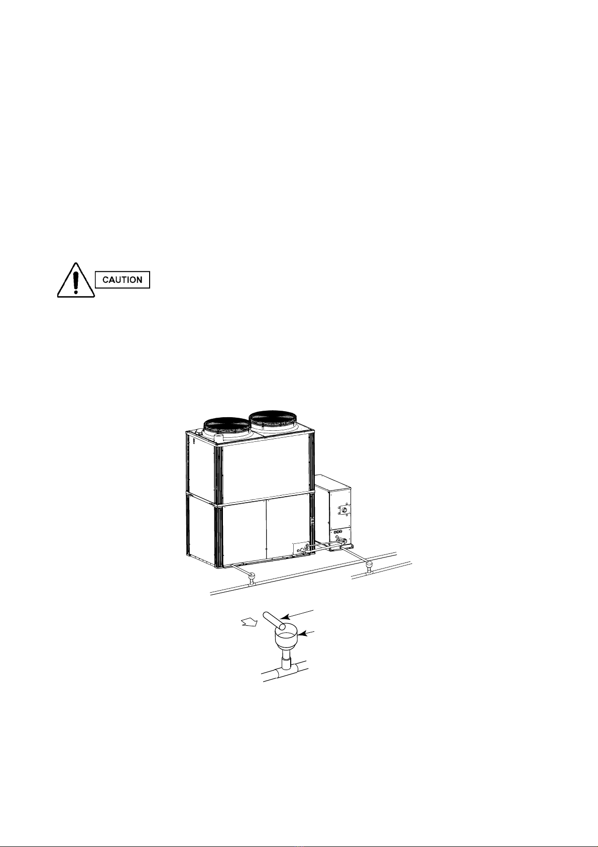
xInstall drain pipes in accordance with the stipulations in "Attention Installation Work Coordinators" to ensure
reliable drainage, while applying insulation to avoid dew condensation. Defective piping work can result in water
leakage, water damage to household effects and other problems.
xPerform the refrigerant pipe insulation work in accordance with the stipulations in "Attention Installation Work
Coordinators." Failure to properly insulate can cause water leakage, burns and other accidents and injuries. (For
thick pipes, use insulation materials with heat resistance of 120°C or above.)
xInstall ground connections, but do not connect the grounding cable to gas pipes, water pipes,
lightning conductors or telephone ground cables. Defective ground connections can cause
electrical shock.
xAlways install a ground leakage breaker.
Failure to attach such a breaker can cause electrical shock and fire.

1. ATTACHMENT
Attached documents
• Procedures and Technical Points for System Installation(Chillers)
• Procedures and Technical Points for Electrical Wiring Work(Chillers)
• Instruction Manual
Concerning anchor bolts
• For anchor bolts, use M10.
• Anchor bolts shall be procured locally.
2. SELECTING THE INSTALLATION LOCATION
CAUTION
1. Secure the space stipulated for inspection and maintenance work (Fig. 2). Inadequate space for
such workcan create the threat of injuries due to falls from the installation site.
2. When installing the water heat exchanger unit on a roof or other elevated location, place permanent
ladders, railings or other aids in passageways to prevent worker falls, as well as fences, railing and
other aids around the unit itself.
3. Install the unit in a location facilitating easy water draining. Defective work in this category can result
in water leakage, water damage to household effects and other problems.
• Keep indoor drain pipe sections as short as possible.
• Insulate all indoor drain pipe sections.
• Adopt measures to ensure that drain water causes no problems for neighboring homes or other parties.
4. Always use a level to confirm the horizontal level.
If it is not flat, water leakage may occur.
1. Avoid installations in locations where machines emitting high frequencies are present.
2. When hoisting up the water heat exchanger unit for installation site delivery:
• Attach ropes to the unit base hoisting fixtures at 4 locations, and raise up the unit.
• When attaching ropes, use wooden splints or other aids to prevent scratching or deformation to
the facing or other damage.
• When hoisting by crane, keep the crane hook at least 1 meter from the unit.
CAUTION
• When carrying in the unit, do not allow it to tip over. Damage to the machinery can cause
subsequent breakdowns.
4
Fig.1 Anchor bolts
312mm
1014mm
Anchorbolts:M10
Over 50mm Over 600 mm
Refrigerant
tubing side
Over 50mmOver 50mm
Over 2m
Wooden splints
Over 1m
Ropes
Fig.2 Fig.3

5
Be sure to perform the following before brazing.
The rubber that fastens the tubes is damaged easily by heat. Be sure to remove it before brazing.
Cool the tubes with wet cloths or other materials to prevent the valves inside the machine from being
damaged by the brazing heat.
Be sure to replace the contents of the tube with nitrogen to prevent the formation of an oxide film.
Do not use commercially available oxide film agents (antioxidants). They can adversely affect the
refrigerant and the refrigeration oil, and can cause malfunctions.
If using flare connections (for the indoor connectors or other part), apply refrigeration oil to the flared
part.
3. REFRIGERANT PIPING WORK
1. When working on the piping, keep the pipe lengths short and the height difference between the units small.
Further, make sure the pipes are not crushed when they are being bent.
The lengths of refrigerant pipes and the difference in height between the water heat exchanger unit and the
outdoor unit are shown in Table 1. According to the Table 1, add the
length of refrigerant piping when they are installed. Also add the unit additional charge amount in Table 2
according to the outdoor unit type.
Fig. 4
2. Remove the gas tube and liquid tube fastening rubber.
3. Connect the tubes and perform brazing.
4. Reattach the gas tube, liquid tube fastening rubber as they were originally.
After cutting tube, be sure to remove all burrs and finish tubing ends to the correct
surface. (The same must be done for branch tubes (purchased separately).)
When cutting or bending tubes, be careful not to cause any pinching or blockage of the
tube.
Take care that no water, dirt, or other foreign substance enters the tube.
Table 1 Allowable refrigerant piping length, amount of refrigerant additionally charged, and pipe specifications
Type Allowable pipe
length
Allowable height difference
When outdoor
unit is higher
When outdoor
unit is lower
50m * 35m
Amount of additional refrigerant
Refrigerant piping (copper
pipe C1220T, external diam-
eter × wall thickness in mm)
Liquid side
(O-material)
Gas side (1/
2H, H-material)
185g/m
56g/m
For the length of
refrigerant piping
Type 500
Type 250
170m (equivalent
length 200m) 15.88 x 1.0 28.58 x 1.0
259g/m
Type 710 19.05 x 1.0 31.75 x 1.1
9.52 x 0.8 22.22 x 1.0
right amount of refrigerant for the
Fig. 5
CAUTION
Tube connection panel
Liquid tube
(narrow tube)
Gas tube
(wide tube)
Liquid tube
fastening rubber
Gas tube
fastening rubber
Tube connection panel
Liquid tube
fastening rubber
Gas tube
fastening rubber
Liquid tube
(narrow tube)
Gas tube
(wide tube)
Table 2 Unit additional charge amount
Outdoor unit type
Unit additional charge amount
45.0 kW
ʊ
56.0 kW
0.5 kg
71.0 kW
2.5 kg
85.0 kW
10.0 kg

6
Fig. 6
Fig. 7
Thermal insulation
(120°C or higher heat
resistance)
Duct (or similar) tape
for waterproofing
Thermal insulation
Liquid tube
(Narrow tube)
Control cable
Gas tube
(Wide tube)
5. Tubing airtightness test and vacuum application
An airtightness test is required for gas heat pump A/C as part of industry installation guidelines. Follow the
procedure below to perform the test and confirm there is no leakage from any connections.
Connect the manifold gauge to both service ports - on the wide tube side and narrow tube side. Then connect the
nitrogen tank, vacuum pump, and other items as shown in Fig. 6.
Use nitrogen to raise the pressure to the airtightness test pressure (4.15
MPa) and confirm that there is no leakage. Refrigerant leakage can cause
suffocation and injury to nearby persons.
Manifold gauge
Pressure gauge
Pressure reducing value
Value
Vacuum pump
Vacuum
gauge
Weight scale
(Outdoor unit)
Close value
(Water heat exchanger unit)
After the airtightness test is completed, apply vacuum of 667 Pa or below to the water heat exchanger unit and
tubing.
Do not leave for a long period of time after the vacuum state has been reached.
6. Charge additional refrigerant. (See Table 1, Table 2, figure 6)
For details, refer to the "To Those Undertaking the Trial Operation."
7. Thermally insulate the pipes.
Thermally insulate the pipes only after checking for leaks at the pipe connection area.
Thermal insulation must be performed on both thick and thin pipes.

7
8. Mixed system composed of the water heat exchanger unit and indoor unit
* If the air conditioning system is a mixed system, the water heat exchanger unit must be connected to the
branch 1 connection on the refrigeration piping. Connect the liquid piping connection that leads to the indoor
unit to the refrigerant liquid piping, that leads to the indoor unit, of the water heat exchanger unit. (Figure 7A)
• Two wrenches must be used to remove the flare nuts from the piping connections, as well as to tighten
the flare nuts onto the ends of the piping.
• Be careful to tighten the flare nuts to the torque as per the table below, as the flares on the flare nuts can
become damaged due to over tightening. If the flares become loose or damaged, the refrigerant gas will
leak, which may cause an oxygen deficiency hazard.
Figure 7A Mixed system piping for a water heat exchanger unit and indoor unit
Outdoor unit
Branch 1
Water heat exchanger unit
Branch 2
Indoor unit Indoor unit
Refrigerant liquid piping leading to the outdoor unit
Refrigerant gas piping
Refrigerant liquid piping leading to the indoor unit
(flare connectors)

4. WATER PIPE WORK
Never use heating mediums other than water in cold-hot water or chilled water. Use of other mediums can cause
fires or explosions.
Always use cold-hot water or chilled water that complies with water quality standards. Deterioration in water
quality can cause breakdowns, water leakage and other problems.
Dispose of brine, cleaning solvents and other waste in accordance with legal stipulations. Illegal disposal not
only violates the law, but can also have a negative impact on the environment.
1. Water pipes may be connected to either the front or the rear of the water heat exchanger unit. Rubber stoppers
are attached to the connecting ports at the time of shipping. Place the accessory plug in connecting port that
is not in use.
2. Install the cold-hot water circulation pump at the water heat exchanger unit inlet pipe side.
3. Water pipe caliber should be equal to or above the connecting port caliber (50A), with as little bending as
possible to reduce pipe resistance. In addition, use union joints or flange joints close to the unit, enabling easy
detachment.
4. Attach appropriate water and air discharge valves to
the water pipes. Allowing air to be mixed into the fluid
inside the pipes can cause noise, corrosion and
declines in capacity.
5. Keep the level of water stored inside the system
above the minimum storage volume.
When the storage water level is low, install a storage
tank or other equipment.
Inadequate amounts of storage water can result in
frequent unit starting and stopping and become the
cause of breakdowns.
6. For test operation, attach a water temperature gauge
and flow rate adjustment valve to the water pipe,
enabling flow rate adjustments in cold water
(hot water) to be made while checking the water
temperature gauge.
Donot touch the adjustment valve once adjustments
have been made.
7. Perform adjustments so that the hydraulic pressure
on the water heat exchanger unit is no more than
0.7MPa.
8. Always attach an expansion tank inside the water
pipe system.
9. For cold-hot water circulation volume (water volume),
operate within the range listed in Fig. 8. Use outside
of this range can cause accidents due to corrosion
or freezing in the heat exchanger.
8
10. Always perform adequate cooling and heat insulation
work on the water pipes.
Inadequate insulation work can result in heat loss, and
also poses the threat of breakage caused by freezing
during severe winter cold.
Cold-hot water flow rate (m3/h)
Hydraulic loss (kPa)
25
20
15
10
5
00123456789101112131415
minimum
requid
flow rate
standard
flow rate
Maximum
allowable
flow rate
S-250WX2E5
Cold-hot water flow rate (m3/h)
Hydraulic loss (kPa)
25
20
15
10
5
00123456789101112131415
minimum
requid
flow rate
standard
flow rate
Maximum
allowable
flow rate
S-500WX2E5
Cold-hot water flow rate (m3/h)
Hydraulic loss (kPa)
25
30
20
15
10
5
05 6 7 8 9 10 11 12 13 14 15 16 17 18 19 20
minimum
requid
flow rate
standard
flow rate
Maximum
allowable
flow rate
S-710WX2E5
Fig.8 Hydraulic Loss Characteristics

9
6. INDOOR INSTALLATION
1. Indoor installation of the water heat exchanger unit will result in dew condensation on the facing,
leading to dripping in some cases. As a countermeasure, a dew catcher or other type of drain pan
should be installed at the bottom of the unit.
Chiller side
Exhaust drain hose
Open to air
(Nominal pipe diameter 50A+)
11. The water heat exchanger unit is equipped with built-in circuits that cause the cold-hot water circulation pump
to operate automatically when the outside temperature drops and the water temperature inside the unit de-
clines to prevent freezing inside the unit. However, when either the unit installation location or cold-hot water
pipe insulation is inadequate, the water temperature inside the pump or cold-water pipes may decline prior to
the water temperature in the unit, resulting in freezing.
In the following cases, install circuits capable of detecting the outdoor temperature at the locations where the
water temperature declines most rapidly throughout the entire water pipe system, prompting automatic opera-
tion of the cold-hot water circulation pump.
12. Attach proper hoisting fixtures to the water pipes to prevent an unreasonable load from being placed on the
water heat exchanger unit.
13. For freezing protection, always turn on the flow switch contact serially with the operational signal.
Flow switch rating:
Turn the contact ON (closed) at flow of;
3m3/h or above for WE80M1 and
4m3/h or above for WE170M1.
5. DRAIN PIPES
•Because the drain consists of natural drainage, always set the drain at a downgrade (1/100 or above).
Setting the drain at an upgrade will cause a backflow in the drain water, which can result in water
leakage.
•Upon completing the pipe work, confirm drainage and check for leaks, then insulate the drain pipe
section installed inside the room. Failure to take these steps can result in water leakage or dew
dripping.
••
••
•Do not share the exhaust drain pipe of the outdoor unit with the drain pipe of the water heat
exchanger unit. The exhaust gas will flow in the water heat exchanger unit and cause a corrosion.
S-250WX2E5
S-500WX2E5, S-710WX2E5

Printed in Japan
DG0312-0
Authorized representative in EU
Panasonic Testing Centre
Panasonic Marketing Europe GmbH
Winsbergring 15, 22525 Hamburg, Germany
Other manuals for S-250WX2E5
1
This manual suits for next models
2
Table of contents