CLIMAVENETA W3000 compact User manual

W3000
Second Edition
USER MANUAL
C0240102-01-10-GB
For software versions GA07
Replaces C0240102-10-09-GB
CLIMAVENETA S.p.A
Via Sarson, 57C
36061 Bassano del Grappa(VI)-ITALY
Tel. (+39) 0424 509 500
Fax (+39) 0424 509 509
http://www.climaveneta.it/
mailto:info@climaveneta.it
H
H
The information contained in this document may be modified without prior notice.
No part of this document may be reproduced and/or disclosed to third parties or competitors. January 2010
GB

C0240102-01-10-GB
2
Contents
1USER INTERFACE................................................................................................................4
1.1Language selection.......................................................................................................5
1.2Menu structure............................................................................................................6
1.3Switching the unit on and off.........................................................................................8
1.4Setting the operating mode...........................................................................................9
1.5Symbols ................................................................................................................... 10
1.5.1Symbols available on individual machines .................................................................. 11
1.6Setting adjustment methods........................................................................................ 12
1.6.1Proportional step adjustment on inlet probe ............................................................... 13
1.6.2Proportional step adjustment on inlet probe + integral on inlet probe............................. 15
1.6.3Quick mind adjustment ........................................................................................... 16
1.6.4Modulating adjustment of screw compressors............................................................. 18
1.6.5Flexible step proportional adjustment on inlet + DIP on outlet probe.............................. 19
1.6.6Neutral zone adjustment on outlet probe + PID on outlet probe .................................... 21
2ALARMS............................................................................................................................22
3TABLE OF MASKS..............................................................................................................29

C0240102-01-10-GB
3
Caution: The W3000 SE controller software is protected by a digital signature.
This means that it can only work on boards supplied by Climaveneta and not on
boards purchased from other dealers.

C0240102-01-10-GB
4
1USER INTERFACE
There are two types of user interface:
Depending on the type of user interface installed, there are more or less keys available for controlling the
unit and for accessing system information.
Key Description
W3000 W3000
compact
[MENU key]: accesses the main menu.
[UP key]: moves around the masks and sets control parameter values
[DOWN key]: moves around the masks and sets control parameter
values
[ENTER key]: confirms entered data.
[ESC key]: goes back one level in the mask tree if you are in the
header masks, or returns to the unit controller.
[ALARM key]: displays the alarms and resets normal operating
conditions.
--- [SETPOINT key]: directly accesses the setpoint menu.
--- [ON/OFF key]: switches the machine on and off.
For each compressor, the following LED's are also located on the W3000 user interface:
Symbol LED colour Description
Green If the LED shines steady the compressor is on, if it flashes the
compressor is demanded.
Red The compressor is blocked by a compressor or circuit alarm
Green The compressor is in the “chiller” mode
Green The circuit is in the “freecooling” mode
Green The compressor is in the “heat pump” mode
Green If the LED shines steady the circuit is in the “recovery mode”, if it flashes
there is a “recovery alarm”
Green If the LED shines steady the circuit is in the “defrost mode”, if it flashes it
is in the “drip mode”
W3000
W3000 com
p
act

C0240102-01-10-GB
5
1.1 Language selection
A special feature of the new hardware is that is has an additional memory containing all the supported
languages: Italian, English, German, Spanish, French, Russian and Swedish.
To select any one of the available languages, proceed as follows.
1) Press [ALARM] and [ENTER] together and hold down until the mask
shown to the side appears. > SYSTEM INFORMATION
LOG DATA
OTHER INFORMATION
F
LASH NAND FILES
2) Press [UP] and [DOWN] to move the cursor “>” to the “FLASH
NAND FILES” row and press [ENTER] to select. SYSTEM INFORMATION
LOG DATA
OTHER INFORMATION
>
FLASH NAND FILES
3) The mask to the side appears to confirm access to the “FLASH
NAND FILES” menu. Now select the file for the required language.
Press [ESC] to exit the menu without changing the language.
[ ]
ga00r00xIT.iup
4) Press [ENTER] to select the language AA. An “X” appears between
square brackets. Press [ENTER] again to deselect the language.
[X]
ga00r00xIT.iup
5) Press [UP] and [DOWN] to view other files.
Files with “.iup” extensions concern the language.
The “.bin” file concerns the application.
The “.grp” file concerns the graphic resources.
[ ]
ga00r00x.grp
6) Just one “.iup” file can be selected. These are the language files, in
fact, specifically: IT Italian, GB English, DE German, ES
Spanish, FR French, RU Russian, SE Swedish.
[X]
ga00r00xIT.iup
7) Select the “.bin” file.
[X]
FLASH1.bin
8) Select the “.grp” file.
[X]
ga00r00x.grp
9) After selecting one of the “.iup” files, the “.bin” file and the “.grp”
file, move to the mask on the side and press [ENTER]. Press Enter
to start copying
9b) On request of the mask to the side, leave “NO” and press [ENTER].
This mask is only used in large applicative versions and may
therefore not appear.
Erase Log data?
NO
press
ENTER to conf.
10) The mask to the side appears indicating that the files are being
copied. copy process
is running
11) After the installation process ends, the mask on the side appears ok, copy completed.
Wait for restart
12) Messages such as “I/O BOARD FAULT” and “NO LINK” may appear
during the process. This is caused by the application restart
process. They will disappear after a few seconds.
I/O BOARD FAULT

C0240102-01-10-GB
6
13) Once the operation has finished, the masks will appear in the
selected language. The installed language can be checked in the
“Unit“ menu.
IT Italian, GB English, DE German, ES Spanish,
FR French, RU Russian, SE Swedish.
W 3000 SE
Code GA 00.00 GB
If all steps of the procedure have been performed correctly, there will be no problems.
However, even if just one file is omitted, the following faults may occur:
N.B. If no “.iup” file is selected, this means that no language has been
selected and an empty mask will appear! Repeat the operation
taking care to select a “.iup” file.
N.B. If the “.bin” file is not selected, it means that the application file has
not been selected. The mask on the side will appear. Press [ESC]
and repeat the operation taking care to select the “.bin” file.
ERROR : press menu
select one blb file
N.B. If the “.grp” file is not selected, it means that the graphics file has
not been selected. The language and the application have been
installed but images will not be processed. Repeat the operation
taking care to select a “.grp” file.
1.2 Menu structure
The tree structures for moving around the various menus are shown below.
Termoregolatore
Selezione
Menù utente
Menù Alarm
Password
utente
Password
assistenza
Power On
Selezione
Menù unità
Selezione
Menù setpoint
Selezione
Menù I/O
Selezione
Menù orologio
Selezione
Menù assistenza
Esc
Esc
Tasto
Menù
Tasto
Alarm
Esc
Esc Menù utente
Menù assistenza
Menù setpoint
Menù I/O
Menù orologio
Esc
Esc
Esc /
Esc /
Esc /
Esc /
Menù unità
Esc
Esc
Esc /
Esc /
Esc Visual. Alarm
Visual. utente
Visual. assistenza
Visual. setpoint
Visual. I/O
Visual. orologio
Visual. unità
Esc /
Esc /
Esc /
Esc /
Esc /
Esc /
Esc /
Esc / Visual. Termoreg.
Tasto
Setpoint
Selezione
Menù storico
Esc Menù storicoEsc / Visual. storicoEsc /
Password
costruttore
Selezione
Menù costruttore
Esc Menù costruttoreEsc /
Esc
Visual. costruttoreEsc /
Figure 1.1: menu tree for W3000-W3000 compact
Thermoregulato
r
Display
Thermoregulator
Menu
ke
y
Unit menu
selection
Setpoint menu
selection
I/O menu
selection
Clock menu
selection
Select log
menu
Select service
menu
Manufacturer
menu selection
Service
password
Factory
Password
Setpoint
key Alarm
ke
y
A
larm menu
Unit menu
Setpoint menu
I/O menu
Clock menu
Log menu
Service menu
Manufacturer
menu
Display alarm
Display unit
Display
set
p
oint
Display I/O
Display clock
Display log
View service
Display
manufacturer
Select user
menu User
password
User menu
Display user

C0240102-01-10-GB
7
The menus are briefly described below:
The “Unit Menu” displays information such as temperature, pressure and circuit states.
The “Setpoint menu” is used to set the setpoints for the various available functions. Different
setpoints can be set depending on the available operating modes (chiller, heat pump and
recovery). Dual setpoint values can also be set for chiller and heat pump operation (only if the
digital input is fitted and the “dual setpoint” function is enabled in the “user menu”).
The “I/O menu” shows the status of the digital inputs and values read from the analogue inputs.
It also shows the status of the digital outputs and the voltage supplied to the analogue outputs.
If expansions are necessary (depending on the configuration parameters), the inputs and outputs
of the latter are also shown.
Parameters relative to user programming of the unit can be displayed and set in the “User
menu”.
Unit configuration parameters can be displayed and set in the “manufacturer menu”.
Service engineers can view and set parameters in the “Assistance menu”.
The list of alarm events recorded by the unit can be displayed in the “Log menu” (only accessible
if the clock card is installed).
The “Clock menu”, if the clock board is present, is used to set and display the date and time and
configure the time bands (except for W3000 base).
After enabling time bands from the “enable time bands” parameter in the “user menu”, time
bands can be set and specific operating modes and different setpoints can be set according to
requirements.
Several time bands (up to 10) of different types (A, B, C and D) can be set during the day.
Figure 1.3 shows an example: the beginning of the first time band is set at 00:00 and the end of
the tenth time band is set at 23:59; the end of one time band determines the beginning of the
following one.
To use a smaller number of bands, set the time a band ends to the same time it begins, and that
band will be ignored. Summer and winter setpoints and unit On/Off switching can be set for each
time band. If the unit is switched Off, it will remain in the “Off from time bands” mode.
Figure 1.3: example of setting time bands
Adjustment
Unit off

C0240102-01-10-GB
8
1.3 Switching the unit on and off
Caution: connect the unit to the power supply at least 8 hours before starting it; if this is not
done, the guarantee will become null and void.
There are different procedures for starting or stopping the unit: using the user interface keys or selecting
from the display. The following procedures have a priority. In the event of conflicts between different
settings, the following priorities apply:
- highest priority: on/off from keypad - on/off from parameter
on/off from digital input
on/off from time bands
- lowest priority: on/off from protocol
Using the [ON/OFF] key:
For W3000
Proceed as follows:
SWITCHING ON: press the [ON-OFF] key.
SWITCHING OFF: press the [ON-OFF] key.
In the W3000, the message Com.: ON appears on the display
In the W3000 base, the message “On” appears on the display with the LED on, or “OFF” with the
LED off.
Using the On/Off parameter:
For W3000 and W3000 compact
The “Com: On/Off” parameter can be displayed on the user interface. “Off” means that the unit is
switched off while “On” means that the unit is switched on.
Proceed as follows:
SWITCHING ON: Move to the “On/Off” parameter by pressing [Enter] and then press [Up] or
[Down] until “On” appears. Press [Enter] again to confirm. If “On” continues to be displayed
it means that the unit has been switched on.
SWITCHING OFF:Move to the “On/Off” parameter and change to “Off” using the same
procedure used to switch the unit on. Press [Enter] again to confirm. If “Off” continues to be
displayed it means that the unit has been switched off.
Using the digital input:
Only if the digital input is fitted.
Open the “user menu” and check that the “On/Off enable from digital input” parameter is set to
“Yes”.
when the contact is open the unit is “Off”, when the contact is closed the unit is “On”.
Proceed as follows:
SWITCHING ON: Close the remote On/Off contact. The “On from digital input” message
appears in the main mask to show that the unit has been switched on.
SWITCHING OFF: Open the remote On/Off contact. The “Off from digital input” message
appears in the main mask to show that the unit has been switched off.
Using time bands:

C0240102-01-10-GB
9
For W3000 and W3000 compact (if the clock board is fitted)
Make sure that the “Clock board not installed” is not displayed in the “clock menu”.
Check that the “Time bands enabled” parameter in the “user menu” is set to “Yes”.
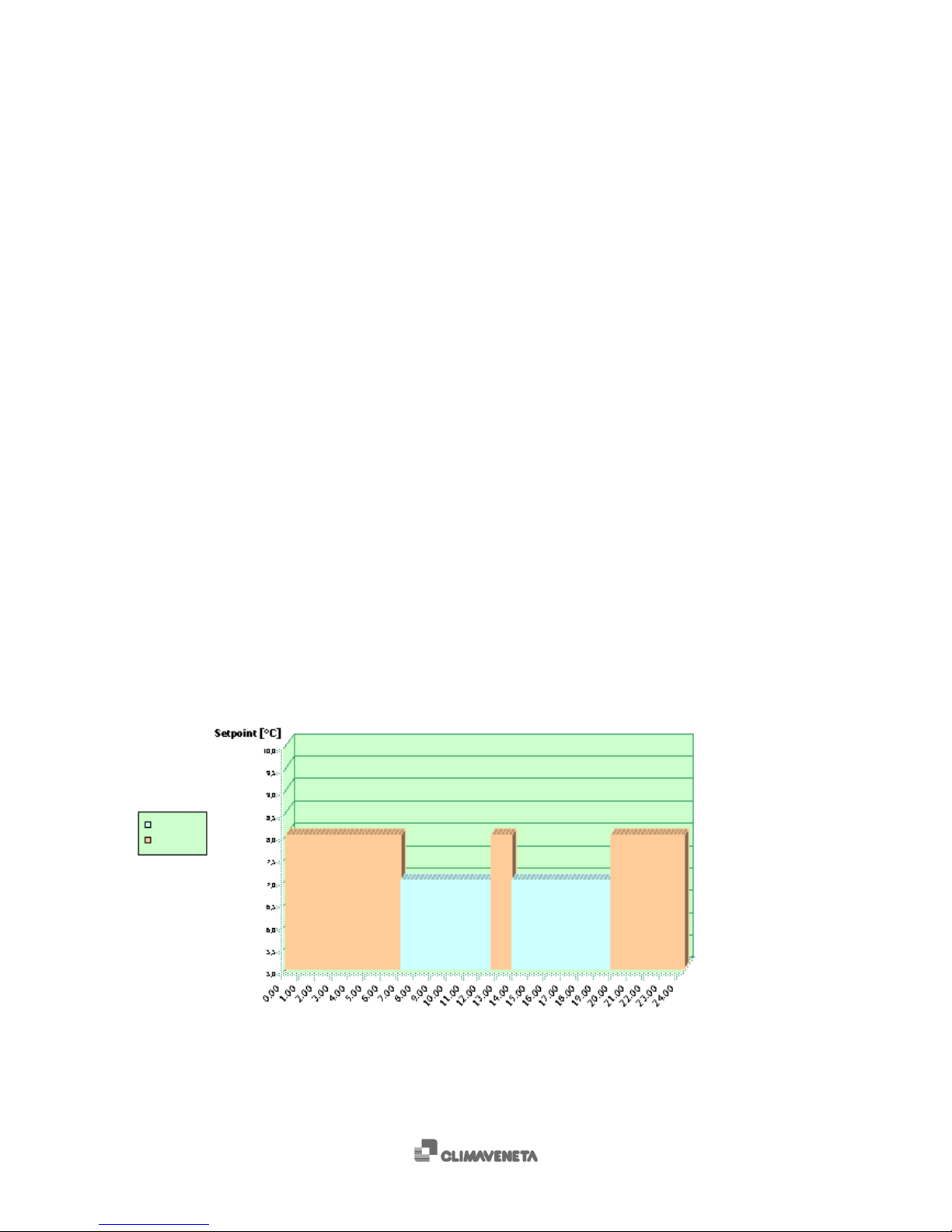
SWITCHING ON: Set the required switching on time in the “clock menu”. The unit switches on
when the set time is reached. The “On from time bands” message appears in the main mask
to show that the unit has been switched on. N.B.: The unit does not switch on if it is set to
“Off from keypad” or “Off from digital input”.
SWITCHING OFF:set the required switching off time in the “clock menu”. The unit switches
off when the set time is reached. The “Off from time bands” message appears in the main
mask to show that the unit has been switched off.
Using the supervision protocol:
Only if the serial board is fitted.
Check that the “Supervisor enable” and “On/Off enable from supervisor” parameters in the “user
menu” are set to “Yes”.
Proceed as follows:
SWITCHING ON: Send the switching on command from the protocol. The “On from
supervisor” message appears in the main mask to show that the unit has been switched on.
N.B.: The unit does not switch on if it is set to “Off from keypad” or “Off from digital input”.
SWITCHING OFF:Send the switching off command from the protocol. The “Off from
supervisor” message appears in the main mask to show that the unit has been switched off.
1.4 Setting the operating mode
Caution: Do not switch from chiller to heat pump unless the inlet temperature is above 15°C.
Do not switch from heat pump to chiller unless the inlet water temperature is below 30°C.
There are various ways of setting the operating mode of the unit.
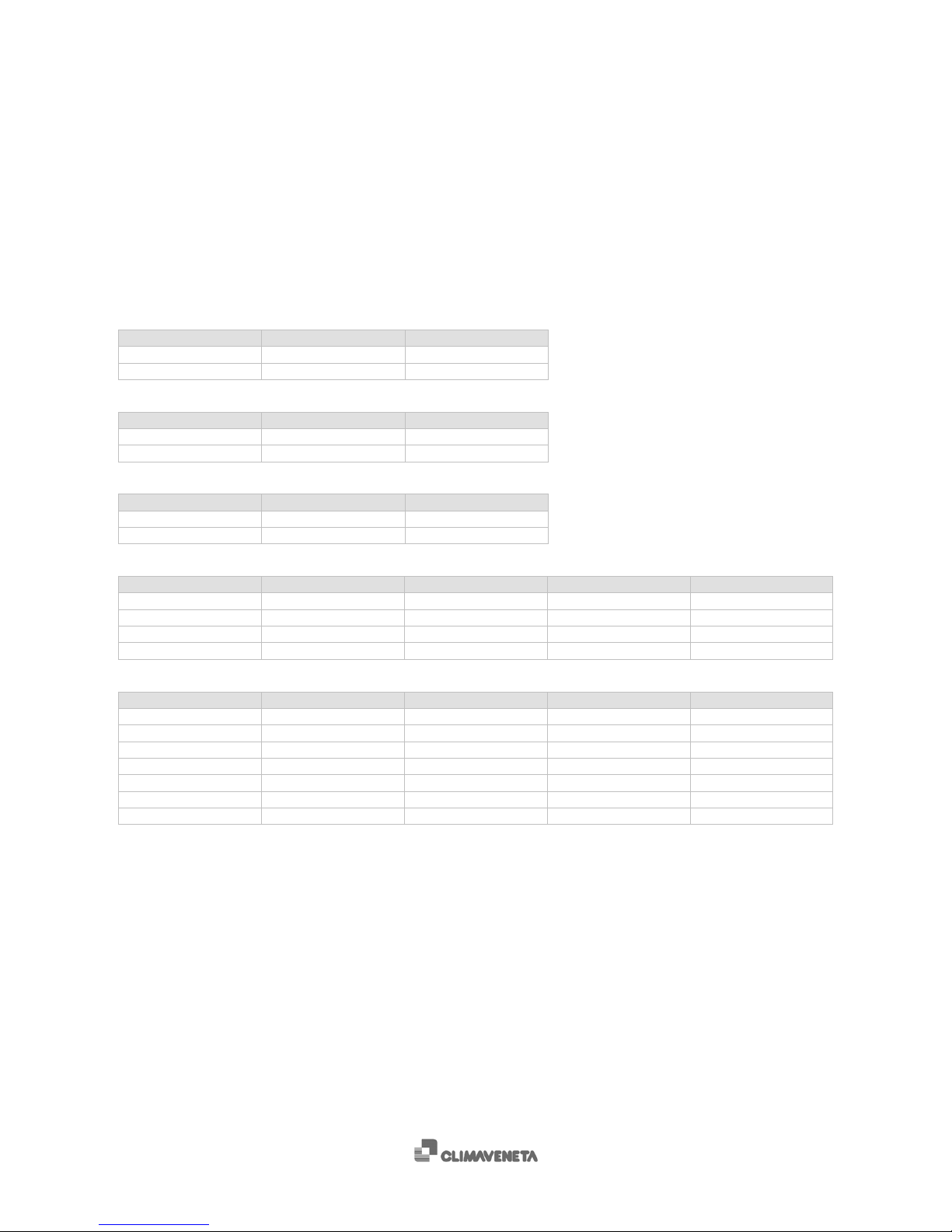
The set operating mode may be any one of the following, as long as they are compatible with the unit:
Operating mode Description
Chiller Chiller
chiller+rec Chiller plus recovery
heatpump Heat pump
summer ch Chiller in summer mode
summer ch+rec Chiller plus recovery in summer mode
summer rec Recovery in summer mode
recovery Recovery only
summer auto Automatic in summer mode
winter hp Heat pump in winter mode
winter rec Recovery in winter mode
winter auto Automatic in winter mode
auto Automatic
N.B.: in water-cooled chillers with water-side reversal the following operating modes are not yet
available: chiller+rec, summer ch+rec, auto, summer auto, winter auto.
The following procedures have a priority: in the event of conflicts between opposing settings the following
priorities apply:
- highest priority: change through parameter
change through digital inputs
- lowest priority: change through protocol
Using the parameter:

C0240102-01-10-GB
10
Make sure the unit is “Off”. Access the “setpoint menu” and display the “Operating mode” parameter.
Move to the “Operating mode” parameter by pressing [Enter] and modify the parameter by pressing [Up]
or [Down]. Press [Enter] again to confirm. If the set message continues to be displayed it means that the
operating mode has been changed.
Using digital inputs:
Applicable in all units with more than one operating mode (all except chiller only).
Open the “user menu” and check that the “Change mode enable from digital input” parameter is set to
“Yes”.
The chiller switches to the operating mode set according to the digital input settings shown in the
following tables:
Heat pump
Operating mode Op. mode value Sum/Win pin
chiller 3 Closed
heatpump 4 Open
Chiller with heat recovery:
Operating mode Op. mode value Rec pin
chiller 3 Closed
chiller+rec 2 Open
Chiller with freecooling:
Operating mode Op. mode value Fc pin
chiller 7 Closed
chiller+fc 8 Open
Energy raisers:
Operating mode Op. mode value Auto pin Sum/Win pin Rec pin
chiller 3 Closed Closed Closed
chiller+rec 2 Closed Closed Open
recovery 1 Open Closed Open
auto 0 Open Closed Closed
Heat pump with recovery:
Operating mode Op. mode value Auto pin Sum/Win pin Rec pin
summer ch 13 Closed Closed Closed
summer ch+rec 12 Closed Closed Open
summer rec 11 Open Closed Open
summer auto 10 Open Closed Closed
winter hp 14 Closed Open Closed
winter rec 15 Open Open Open
winter auto 16 Open Open Closed
The operating mode changes with digital inputs without the unit switching off. Only the sum/win digital
input switches off the unit, changes the operating mode and switches the unit back on again.
E.g.: - switching between “summer auto” and “summer recovery” does not switch off the unit,
- switching between “summer auto” and “winter auto” switches off the unit.
Using the supervision protocol:
Only applicable if the serial board is fitted.
Check that the "Supervisor enable" and "Change operating mode enable from supervisor" parameters in
the "user menu" are set to "Yes".
Make sure the unit is “Off”. Send the change operating mode command from the protocol. The operating
mode only changes if the unit is switched off.
The value restored to the protocol (or to send to the protocol) is the same as that shown in the
supervision database. For simplicity it is shown in the above tables divided by type of unit.
1.5 Symbols
The following symbols are used in the W3000 and W3000 compact masks.

C0240102-01-10-GB
11
Flashing
items
main mask
Description
BANDS Time bands active
FCOOL Unit in free-cooling mode
LIMIT Power limit active (demand limit)
FREEZE Outlet temperature approaching anti-freeze setpoint
ERR Y3 Analogue output configuration error. Switch the controller off and back on again
U.ALONE The unit works independently after disconnecting the Manager3000 or Sequencer
HPTC Circuit limitation enabled due to elevated condensation
DEFR Defrosting is active on one or more circuits of the unit
Symbol
unit menu Description
Off Unit/circuit off
Ch nr Chiller circuit not demanded by thermoregulator
Ch Chiller circuit demanded by thermoregulator
Ch+R Chiller circuit plus recovery demanded by thermoregulator
Hp nr Heat pump circuit not demanded by thermoregulator
Hp Heat pump circuit demanded by thermoregulator
R nr Recovery only circuit not demanded by thermoregulator
R Recovery only circuit demanded by thermoregulator
Pd Circuit in pump-down mode
Defr Circuit in defrost mode
Drip Circuit in drip mode
1.5.1 Symbols available on individual machines
Chiller Symbol Description
chiller Chiller
Chiller+freecooling Symbol Description
chiller Chiller
chiller+fc Chiller plus freecooling
Chiller+recovery Symbol Description
chiller Chiller
chiller+rec Chiller plus recovery
Heat pump Symbol Description
chiller Chiller
heatpump Heat pump
All-in-one Symbol Description
auto Automatic
recovery Recovery
chiller+rec Chiller plus recovery
chiller Chiller
Heat pump with recovery Symbol Description
summer auto Summer automatic
summer rec Summer recovery
summer ch+rec Summer chiller plus recovery
summer ch Summer chiller
winter hp Winter heat pump
winter rec Winter recovery
winter auto Winter automatic

C0240102-01-10-GB
12
1.6 Setting adjustment methods
Depending on the type of compressor used, various adjustment methods may be selected.
Compressor Type of unit Adjustment method
Hermetic
Water/water heat pump Quick Mind on outlet probe
Quick Mind on inlet probe
Proportional step on inlet probe
Proportional step on inlet probe + integral on inlet probe
Water/water chiller
Evaporating units
Water/air heat pump
Water/air chiller
Chiller with heat recovery (*)
Chiller with free-cooling Proportional step on inlet probe
Proportional step on inlet probe + integral on inlet probe
Energy Raiser (*)
Heat pump with recovery (*)
Alternative
Chiller with free-cooling
Proportional step on inlet probe
Proportional step on inlet probe + integral on inlet probe
Energy Raiser (*)
Heat pump with recovery (*)
Chiller with heat recovery (*)
Water/water heat pump
Water/water chiller
Evaporating units
Water/air heat pump
Water/air chiller
Screw
Water/water heat pump
Modulating on outlet probe
Proportional step on inlet probe
Proportional step on inlet probe + integral on inlet probe
Water/water chiller
Evaporating units
Water/air heat pump
Water/air chiller
Chiller with heat recovery (*)
Chiller with free-cooling
Energy Raiser (*) Proportional step on inlet probe
Proportional step on inlet probe + integral on inlet probe
Heat pump with recovery (*)
Screw with
inverter
Water/water chiller Flexible step proportional on inlet probe + DIP on outlet
probe
Neutral zone on outlet probe + DIP on outlet probe
(adjustment required for unit with pump speed control)
Water/air chiller
Centrifuge Water/water chiller Flexible step proportional on inlet probe + DIP on outlet
probe
Water/air chiller
Table 1.1: heat adjustment methods available by compressor type
(*): on the heat recovery circuit, only the proportional step adjustment on the inlet probe is available for
these units.
The various heat adjustment methods are described below.

C0240102-01-10-GB
13
1.6.1 Proportional step adjustment on inlet probe
Some examples of proportional “step” adjustment on the inlet temperature probe:
Tin
Banda proporzionale
N%
50%
100%
Set Set + banda
proporzionale/2
Caso chiller (n° di gradini = 2)
Figure 1.4: TBin Bis the input variable, NB%Bis the number of active steps expressed in % (chiller).
Tin
Banda proporzionale
N%
50%
100%
Set
Set - banda
proporzionale/2
Caso pompa di calore (n° di gradini = 2)
Figure 1.5: TBin Bis the input variable, NB%Bis the number of active steps expressed in % (heat pump).
Chiller (n° steps =2)
Set + proportional band/2
proportional band
Heat pump (n° steps =2)
Set + proportional band/2
proportional band

C0240102-01-10-GB
14
The following tables show some typical values for the parameters in question. The theoretical maximum and
minimum outlet temperature values refer to operation at nominal flow rates (with a thermal head at the
evaporator of 5 °C and sufficient water in the system to ensure a litre / KW ratio equal to or greater than 7).
N°
steps Setpoint
(°C) Proportional band
(°C) Theoric min. outlet T
(°C) Theoric max. outlet T
(°C)
2 9.5 2.5 5.7 10.8
4 7 5 5.7 8.3
6 7 5 6.2 7.8
Table 1.2: normal setpoint and proportional band values according to the number of steps (chiller).
N°
steps Setpoint
(°C) Proportional band
(°C) Theoric min. outlet T
(°C) Theoric max. outlet T
(°C)
2 42.5 2.5 41.2 46.3
4 45 5 43.7 46.3
6 45 5 44.2 45.8
Table 1.3: normal setpoint and proportional band values according to the number of steps (heat pump).

C0240102-01-10-GB
15
1.6.2 Proportional step adjustment on inlet probe + integral on inlet probe
This adjustment method is based on the sum of two components: proportional and integral.
The proportional component generates the percentage demand for activating/deactivating the steps, as
illustrated in the previous paragraph “Proportional step adjustment on inlet probe”.
The integral component adds the integral error to the proportional component at regular intervals
(integral time: parameter 55.02). The integral error is calculated according to the following formula:
Integral error = Inlet temperature – Set point x 100 [%]
Proportional band
However, the integral component is limited (integral limit: parameter 55.03) to prevent the adjustment
If the inlet temperature varies by 5% or more in one second, a rapid change, therefore, the integral
component is not calculated.
Set point
Set point
+
Banda p.
Tin
Compr.
Accesi
2
1
0 %
50 %
100 %
Inte
g
rale
+ limite
- limite
Proporz.
+
Integrale
0 %
50 %
100 %
tempo
Integrale tempo
Integrale tempo
Integrale tempo
Integrale tempo
Integrale
Componente integrale
Componente a gradini
Fig 1.6 Example of a 2 step adjustment in the chiller mode
Set point
+
P. band
+ limit
Integral
- limit
Prop.
+
Integral
Compr.
On
Integral
time Integral
time Integral
time Integral
time Integral
time
Integral component
Compr.
On
Step component

C0240102-01-10-GB
16
1.6.3 Quick mind adjustment
Users must set the required setpoint as the other parameters are adapted to the system by the Quick
Mind algorithm.
QUICK MIND is a self-adapting algorithm for adjusting the temperature of the water treated by an all-in-
one unit. The following figure shows how this adjustment is made:
Tout
ZONA NEUTRA
Setpoint
Attivazione compressori
Disattivazione compressori
ESTATE
Figure 1.7: QUICK MIND adjustment model (chiller and heat pump)
The setpoint remains within a dead area. If the temperature also remains within this area, no change is
made to the number of active compressors.
When the temperature leaves the dead area following a change in system load, the compressors are
either activated or deactivated in order to return the temperature to the dead area.
The amplitude of the neutral zone depends on the dynamic characteristics of the system and, in
particular, on the amount of water it contains and the load. The self-adapting algorithm is able to
“measure” system dynamics and calculate the minimum dead area in order to respect compressor
activation times and the maximum number of start-ups per hour.
Both return and delivery temperatures can be adjusted.
Special functions are also present which reduce the number of compressor start-ups in the event of very
low loads or start-ups of units with significantly higher or lower temperatures than the setpoint.
Compressors deactivated
SUMMER
DEAD AREA Compressors activated
WINTER
DEAD AREA Compressors deactivated
Compressors activated

C0240102-01-10-GB
17
2 compressors - with maximum permitted number of start-ups per hour 10
Litres / KW 10.5 9.5 8.5 7.5 6.5 5.5 4.5 3.5 2.5
out 3.2 3.3 3.4 3.5 3.6 3.8 4.1 4.5 5.3
4 compressors - with maximum permitted number of start-ups per hour 10
Litres / KW 10.5 9.5 8.5 7.5 6.5 5.5 4.5 3.5 2.5
out 1.6 1.6 1.7 1.7 1.8 1.9 2.0 2.2 2.6
6 compressors - with maximum permitted number of start-ups per hour 10
Litres / KW 10.5 9.5 8.5 7.5 6.5 5.5 4.5 3.5 2.5
out 1.1 1.1 1.1 1.2 1.2 1.3 1.3 1.5 1.7
Table 1.4: maximum theoretical delivery temperature range at constant part load (depending on the quantity of water
contained in the system) with outlet Quick Mind adjustment
An example of real data acquired during operation with the Quick Mind adjuster on the delivery side is
shown below. Reference is made to the following figure:
Fase di avviamento controllato = Controlled starting phase
Adattamento zona neutra = Adaptation to dead area
Temperatura uscita evaporatore = Outlet temperature of evaporator
Temperatura ingresso evaporatore = Inlet temperature of evaporator
1 compressore attivo = 1 compressor active
2 compressori attivi = 2 compressors active
Figure 1.8: example of real data with quick-mind outlet adjustment (x-axis: time in [s]; y-axis: Tout in [°C] ).
This is an example of start-up with a very high initial temperature compared with the setpoint (7°C).
About 10 seconds after data acquisition began, one compressor switches on. The second compressor
does not switch on immediately as the algorithm which handles start-up checks if one compressor is
enough to return delivery temperature to the setpoint and avoid unnecessary start-ups. As the delivery
temperature is still at 12 °C after about 200 seconds, the second compressor is also switched on,
otherwise it would take too long to reach setpoint.
Following the controlled starting phase, the delivery temperature falls until it “enters” the dead area. The
algorithm (at t= 350 s) begins to adapt the amplitude of the dead area in order to respect compressor
safety times. As can be seen, the dead area is later reduced (t= 780 s, 950 s) to the absolute minimum
amplitude which allows safety times to be respected. It can also be seen that the compressors are
activated and deactivated when the outlet temperature reaches the upper or lower limits of the dead
area. The example shows that outlet temperature varies by about 3.5 °C during regular operation.

C0240102-01-10-GB
18
1.6.4 Modulating adjustment of screw compressors
With screw compressors, modulating adjustment is performed on the outlet probe.
Modulating adjustment is only available on “Bitzer” screw compressors.
set point t [min]
Tout [°C]
ZN
B(increase)
C(decrease)
Reference is made to the figure to the left:
The setpoint remains within a dead area. If
the temperature also remains within this
zone, no change is made to the number of
active compressors or their load
percentages (position of modulating
chamber).
When the temperature rises above zone B
following a change in the system load, the
compressors are activated in order to return
the temperature to the dead area.
Inside zone B, if the outlet temperature
derivative is greater than or equal to 0,
compressor power is increased in order to
return the temperature to the dead area
(ZN). The further away the temperature is
from the setpoint, the greater the increase
is.
Figure 1.9: modulating adjustment for screw compressors
When the temperature falls below zone C following a change in the system load, the compressors are
either deactivated in order to return the temperature to the dead area.
Inside zone C, if the outlet temperature derivative is less than or equal to 0, compressor power is
decreased in order to return the temperature to the dead area (ZN). The further away the temperature is
from the setpoint, the greater the decrease is.
The amplitude of the neutral zone depends on the dynamic characteristics of the system and, in
particular, on the amount of water it contains and the load. The self-adapting algorithm is able to
“measure” system dynamics and calculate the minimum dead area in order to respect compressor
activation times and the maximum number of start-ups per hour.
When a second or subsequent compressor is switched on, the ones that are already running are forced to
a minimum, and the subsequent power increases/decreases are applied to all the compressors.

C0240102-01-10-GB
19
1.6.5 Flexible step proportional adjustment on inlet + DIP on outlet probe
This adjustment is performed by two independent adjusters:
a) Proportional step (step adjuster) on the inlet probe;
b) DIP (fine adjustment) on the outlet probe.
The set point is identical for both adjusters.
a) This is a proportional step adjuster whose control variable is the inlet temperature to the Tin unit and
whose controlled variable is the number of steps to enable (compressors).
Compared with the traditional step adjuster, 2 further parameters have been added.
Rb: is a percentage of the proportional band BP and allows the steps to be compressed in this part of the
proportional band.
Rb
Isteresi
Banda proporzionale BP
Set point Sp
Tin
Esempio funzionamento 4 gradini in raffreddamento e Rb < BP
Gradini attivi
Figure 1.10: proportional step adjuster with offset = 0 and Rb = 50%
The hysteresis of each step is the reference proportional band Rb divided by the number of steps to
manage.
Operating example of 4 cooling steps and Rb < BP
Active steps
Hysteresis
Proportional band BP

C0240102-01-10-GB
20
The Offset moves the enable/disable of the second half of the steps to a higher value with respect to
offset = 0.
Banda proporzionale BP
Set point Sp
Tin
Esempio funzionamento 4 gradini in raffreddamento e Offset > 0
Rb
Offset
Gradini attivi
Caso offset = 0
Figure 1.11: proportional step adjuster with offset > 0 and Rb = 50%
b) The DIP (Derivative Integral Proportional adjuster), whose control variable is the outlet temperature,
activates after a settable delay from the start of the first compressor and deactivates after the last one
stops.
The controlled variable is the number of compressor revs (absorbed power per unit with centrifugal
compressors), changing them from the settable minimum to maximum, thus achieving fine adjustment of
the outlet temperature.
The following parameters can also be adjusted: kp (coefficient of proportional component) and ti (integral
time). The derivative time is factory set.
Operating diagram
T outSet point Sp
Zona
neutra
Zona
forzatura
al minimo
Zona
forzatura
al massimo
Zona
regolazione
PID
Zona
regolazione
PID
zfi zfs
Figure 1.12: operating diagram of DIP adjuster output
When the outlet temperature lies within the neutral zone, the compressor revs are not modified.
When the outlet temperature lies within the DIP adjustment zone, the value of the compressor revs is
modified to return the temperature to within the neutral zone.
The zfi, neutral zone and zfs parameters are factory set.
Operating example of 4 cooling steps and Offset > 0
Active steps
Offset = 0
Proportional band BP
Minimum
override
zone
DIP
adjustment
zone
Neutral
zone
DIP
adjustment
zone
Maximum
override
zone
Other manuals for W3000 compact
1
Table of contents
Other CLIMAVENETA Chiller Control System manuals