CE
Specification
Rated Operating Voltage
Operating Voltage Range
Rated Current Consumption
Ambient Temperature (in use)
Storage Ambient Temperature
Ambient Humidity (in use and storage)
21.6 to 26.4 V DC (including ripples)
24 V DC
0 to 50∞C (no freezing or condensation)
-20 to +60∞C (no freezing or condensation)
35 to 75%
(at 25∞C with no freezing or condensation)
0.7 A max. (1 camera) 0.9 A max. (2 cameras)
Noise Immunity
Vibration Resistance
Shock Resistance
Weight
1000 V pulse width 50 ns/1 µs
(using noise simulator method)
10 to 55 Hz, 1 cycle/1 min.
Double amplitude of 0.75 mm.
30 min. each in X, Y and Z directions
196 m/s2, 5 times each in X,Y and Z directions
Approx. 450g
Product Name
Durable extention 2 m: Total 5 m
Durable extention 7 m: Total 10 m
Durable extention 12 m: Total 15 m
Durable extention 17 m: Total 20 m
ANM84002A
ANM84007A
ANM84012A
ANM84017A
ANM84002ACE
ANM84007ACE
ANM84012ACE
ANM84017ACE
ANM84502
ANM84507
ANM84512
ANM84517
ANM831
ANPV0310JDN
ANPV0310JDP
ANPV0310EDN
ANPV0310MDP
Ultra-
Compact
Camera Lens
Ultra-Compact Lens 12mm
Ultra-Compact Lens 12mm
Ultra-Compact Lens 12mm
f8.5
f16
f16
f25
f25
f50
f50
f50
f4
f12
f30
ANMX8300
ANMX8301
ANMX8302
ANMX8303
ANMX835
ANMX83310
ANMX83311
ANMX83312
ANMX83313
ANMX83330
ANMX83331
ANMX83332
ANMX83333
ANPV3700
ANB843L
ANB845NL
ANM88161
ANB846NL
ANM88251
ANB847L
ANM8850
ANM88501
ANPVL0401
ANPVL1201
ANPVL3001
ANB84805
ANB848
ANM85202
ANM85203
ANM85205
ANM85210
ANM85202CE
ANM85203CE
ANM85205CE
ANM85210CE
Double-Speed Random
Camera Cable
(Durable Type) = 3 m
ANM832
ANM832CE
ANM83203
ANM84303
ANM84303CE
ANM84603
ANPVCA1012
JPN/ENG
JPN/ENG
ENG/JPN
ENG/GER/FRN/ITA/SPN
NPN
PNP
NPN
PNP
ANM81103
ANM81303
10 11
Functional Specifications Specification
Specification
Functional Specifications
Settings Data Storage Capacity
Frame Memory
Operation
Environment
Cameras
Monitor Output
Memory Card
Serial
Parallel
Keypad Input
Tools
Input/Output
Approx. 4 MB
512 x 480 (pixels)
Menu selection by dedicated keypad
Key Emulation
Menu selection by serial command
2 Standard cameras, double-speed random
cameras, or ultra-compact cameras
(max. 4 cameras when using camera switching
unit, excluding ultra-compact camera)
Color VGA ouput
RS-232C x 1 channel
Input: 13 points; output: 14 points;
removable screw-down terminal block
Compact Flash: 1 slot
1 Connector for dedicated keypad (ANM8520*)
Ethernet: 1 channel
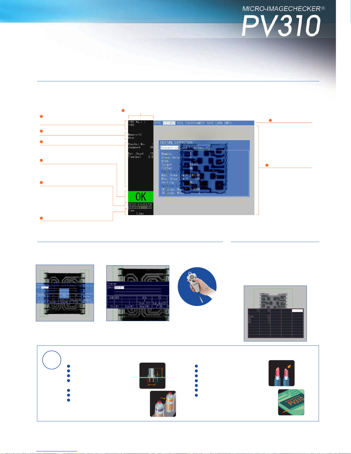
Image Processing Functional Specifications
Monitor Display
Number of Connected
Cameras
Processing Method
No. of Product Types
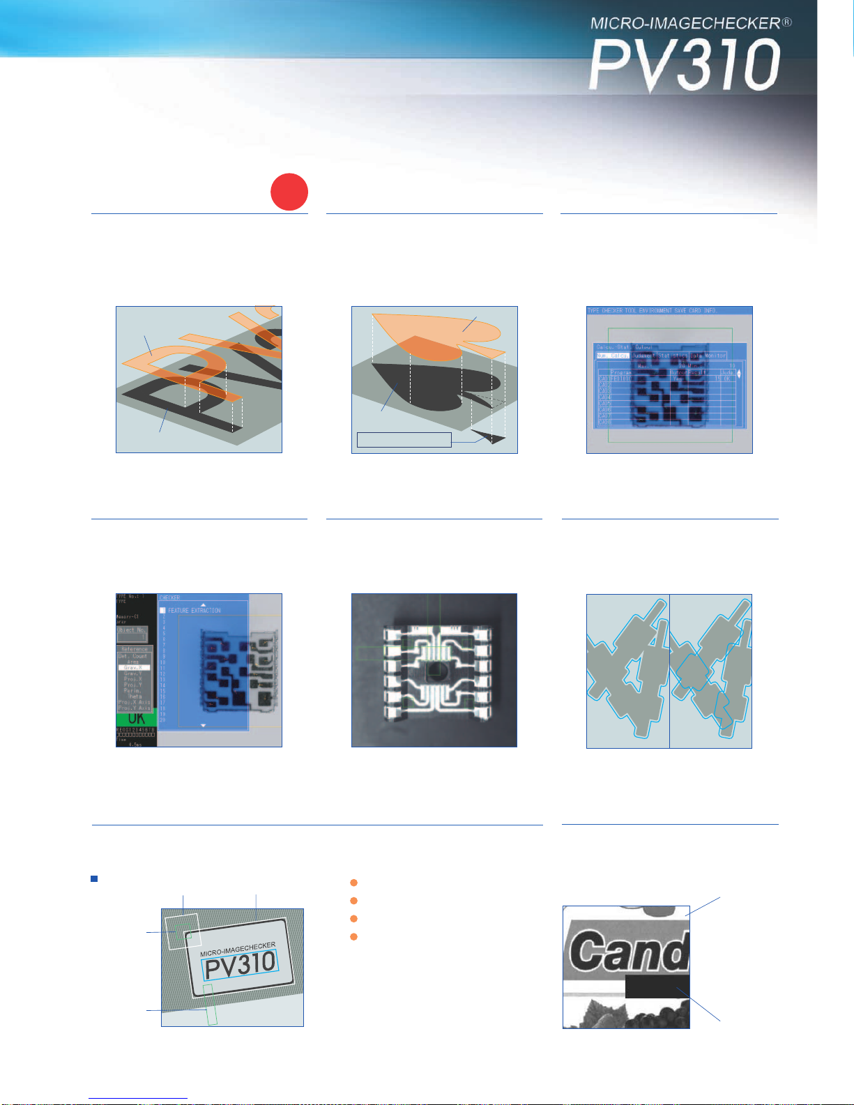
Inspection Functions
Numerical
Computation
Judgment Output
Statistics
Data Monitor
Full color VGA/gray scale image/
binary image
Two-screen compressed display: side-by-side
display (when gray scale image selected)
through/memory, data monitor, marker,
+ information display region (128x480)
Max. 2 cameras (Max. 4 cameras using camera
switching unit, excluding ultra compact camera)
Gray scale processing - Binary processing
Max. 64 types
(depends on settings data capacity)
Max. 99 checkers/product type
•Position adjustment, rotation adjustment,
binary window
•Gray scale window, binary edge, gray scale
edge
•Feature extraction, smart matching, contour
matching, scratch detection
Max. 96 functions/product type
Operators:
4-operation calculation, , arc tangent,
distance between 2 points,
parenthesis, sin, cos, absolute value of
difference
Max. 96 functions/product type
Operators:
NOT/AND/OR/XOR/parenthesis
Max. 96/product type
Calculation of no.of passes/no.of fails/pass
average/pass distribution/
pass max. value/pass min. value/pass range
(for judgment output no. of passes/no.of fails
only)
Max. 50/product type
Displayed on screen in table form during RUN
Title input and substitution of numerical
computation results, judgment output results,
statistical results and product numbers
possible
RS-232C=1ch (max. speed 115200 bps)
Specification
Operation Data
Marker
External Input/Output
Serial
Parallel
CF Card
(1 slot)
Ethernet
(1 channel)
Other
Display
Functions
Collective
Movement
Image Storage
Setting Help
Calendar
Password
Max. 4/environment
Substitution in numerical computation possible
Max. 8/product type
Graphic display on screen during RUN
ItemItem
Item
• Input: start/product type switch/camera
display switch/template re-registration/
CompactFlash settings restore/reference to
and alteration of upper and lower values for
numerical computation/reference to and
alteration of binary level/reference to and
alteration of gray scale edge thresholds/data
storage/fixed length input for input commands
for statistics initialization (for PLC)
• Output: output (no. of inspections/judgment
output/numerical computations/statistics)
synchronous or asynchronous to inspection
start trigger
• Computer link support:
Supported models:
• Matsushita Electric Works PLC
• OMRON Corporation - C, CV and CS1 series
•
Mitsubishi Electric Corporation - A, Q and FX series
• Rockwell Automation DF1 protocol
• Fuji Electric SX series
Input: 13 points; output: 14 points
• Input: start/product type switch/camera
display switch/template re-registration/
data restore from Compact Flash
• Output: ready/error/flush/image
acquired/strobe/judgment output data/
synchronous output (no.of inspections/
judgment output/numerical computation/
statistics) possible by handshake output
• Output: no.of inspections/judgment
output/numerical computations/statistics/
settings data/image backup and
restore/conversion to documentation for
settings data (Vision AXTOOL)
• Output: no.of inspections/judgment
output/numerical computations/statistics/
settings data/image backup and restore/screen
dumps
Transparent menu/parallel output status
monitor/reference coordinate display/checkers
with fail results highlighted in different color
Collective movement of set checkers in units
of position/rotation adjustment groups
Max. 16 images/camera
Each time/storage possible according to
judgment result
Test runs available on stored images
Display of date and time saved
Function to maintain display of last image
saved
Focusing/aperture adjustment/parallel monitor/
lighting adjustment/gray scale profile display
Calendar information added to stored images
File time stamp
Password function for when moving between
settings modes
Dimensions(Unit: mm) Part Nos. and Specifications
Part Nos.
Specification Specification
Rated Operating Voltage
Operating Voltage Range
Rated Current Consumption
Ambient Temperature (in use)
Storage Ambient Temperature
Ambient Humidity (in use and storage)
21.6 to 26.4 V DC (including ripples)
24 V DC
0 to 50∞C (no freezing or condensation)
-20 to +60∞C (no freezing or condensation)
35 to 75%
(at 25∞C with no freezing or condensation)
0.7 A max. (1 camera) 0.9 A max. (2 cameras)
Noise Immunity
Vibration Resistance
Shock Resistance
Weight
Product Name Product Name
Specification Part No.
PV310 Controller
Double-Speed Random
Camera (C Mount) progressive support
Ultra-Compact Camera
12-mm diameter
Standard Camera
(CS Mount)
3 m
3 m
with 3 m cable
with 3 m cable
with 30 cm cable
Double-Speed
Random Camera
Cable
Product Name
Camera Extension
Cable
Camera Switching
Unit
Supports standard camera
and double-speed random
camera
VGA Monitor With keypad connector
Without keypad connector
Kit for
Installation
on Main Unit
With keypad connector.
Mounting brackets
(ANMX835)/Monitor cable:
0.5 m/Keypad cable: 0.5 m
Without keypad connector.
Mounting brackets
(ANMX835)/Monitor cable:
0.5 m
Controller
Mounting
Brackets
Brackets for mounting
VGA monitor on the
controller
(With keypad
controller)
Keypad Cable
for Connection
to Main Unit
C Mount
Lens
Adapter Ring
Operation Keypad
Monitor
Cable
Keypad Cable
(between VGA monitor and
controller)
ANMX8333*
Main Unit (Controller)
ANPV0310EDN Operation Keypad
ANM852**
ANM852**CE
Double-Speed Random Camera: C Mount
ANM831
Ultra-Compact Camera
ANPVCA1012
Double-Speed Random Camera Cable
ANM84303
ANM84303CE
Lens Camera Switching Unit
ANPV3700
2 m extension:Total 5 m
7 m extension:Total 10 m
12 m extension:Total 15 m
17 m extension:Total 20 m
2 m extension:Total 5 m
7 m extension:Total 10 m
12 m extension:Total 15 m
17 m extension:Total 20 m
Cable length:0.5 m
(for single-unit mounting)
Cable length:1 m
Cable length:2 m
Cable length:3 m
Cable length :0.5 m
Cable length:1 m
Cable length:2 m
Cable length:3 m
C mount lens with lock
C mount lens with lock
C mount compact lens with lock
C mount compact lens
C mount compact lens with lock
C mount super-compact lens with lock
C mount super-compact lens with lock
C mount super-compact lens
COM Port
Cable
5 mm
0.5/1/5/10/20/40 mm
with 2 m cable
with 3 m cable
with 5 m cable
with 10 m cable
with 2 m cable
with 3 m cable
with 5 m cable
with 10 m cable
for connection to PC
(D-SUB: 9 pins): 3 m
for connection to PLC
(discrete-wire cable):3 m
223
220
55 55
90
160
45
43
2
AB
f=8.5
f=16
f=25
f=50
f=16
f=25
f=50
f=50
ANB843L
ANB845NL
ANB846NL
ANB847L
ANM88161
ANM88251
ANM8850
ANM88501
40
33
37.3
48
25
25.5
38.5
38.5
φ42
φ30
φ30
φ48
φ30.5
φ30.5
φ27.5
φ30.5
40
40
12
12
L
5.4
5.4
35.4
96
48
29.5 59
74.6
51.4
25.4
5
57.2
5.5
26.5±0.5
86.0
±
0.5
36
(10)
130
10059
4.6
5
258
255
3540 10
160
55 55
45
43
2
AB
f=4
f=12
f=30
ANPVL0401
ANPVL1201
ANPVL3001
14.8
14.4
25.3
φ12
φ12
φ12
(5) (Pullout dimensions)
Note *2) This is the length of cable in use.
Becomes slightly shorter with CE attached.
Mounting screws (lenses with lock only)
Note *1) ANM832: 3000
ANM832CE: 2780
ANM83203: 300
Standard Camera: CS Mount
ANM832/ANM832CE/ANM83203
C Mount Lens
Specification
Rated Operating Voltage
Operating Voltage Range
Rated Current Consumption
Ambient Temperature (in use)
Storage Ambient Temperature
Ambient Humidity (in use and storage)
21.6 to 26.4 V DC (including ripples)
24 V DC
0 to 50°C (no freezing or condensation)
-20 to +60°C (no freezing or condensation)
35 to 75%
(at 25°C with no freezing or condensation)
0.7 A max. (1 camera) 0.9 A max. (2 cameras)
Noise Immunity
Vibration Resistance
Shock Resistance
Weight
Dimensions (mm)
1000 V pulse width 50 ns/1 µs
(using noise simulator method)
10 to 55 Hz, 1 cycle/1 min.
Double amplitude of 0.75 mm.
30 min. each in X, Y and Z directions
196 m/s2, 5 times each in X,Y and Z directions
Approx. 450 g
W59 ×H130 ×D100 (with connector 110)
General Specifications
Item
Controller: ANPV0310 Specification
Camera Switching 2-camera input - 1-camera output
(Switching by external signal input/Manual switching)
Camera Image Split
ANM832 (CE) only 2-camera input - 1-camera output of top/bottom
split images/
2-camera input - 1-camera output of left/right
split images
External Switching
Signal Input 1 input, photo-coupler bidirectional input
supported, 5 to 24 V DC
DIP Switch Setting LOCAL/REMOTE, NORMAL/DIV, A/B,
Top-Bottom/Left-Right
Rated Voltage Range 12 V DC (supplied from the MICRO-
IMAGECHECKER unit)
Weight
Included items: 1 connection cable (30 cm), 2 ferrite cores, and
1 installation manual
The operation condition requirements are the same as those for the PV310
Controller.
Approx.150 g (Main unit only)
Functions
Item
Camera Switching Unit: ANPV3700
Ultra-Compact Lens
ANMX8301
CCU
9.5 (Pullout dimensions)
DIN hook
*1)
VGA Monitor
ANMX8301
VGA Monitor Cable
ANMX8331*
Without mounting bracket With mounting bracket
The boxes correspond to the length of cable in use.
2-M3(
Depth
4mm) 4-M3
(
Depth
2.5mm)
13
19
26
31
10
54.5
(46.5)
8
31
29
(31.3)
2.5
31 1/4-20UNC
(
Depth
9mm)
(19)
(3.25)
24.5
±
0.6 24.5
±
0.6
±
0.6
31
29
4-M3 (
Depth
2.5mm) 2-M3 (
Depth
7mm)
2-M3 (
Depth
4mm)
24.5
±
0.2
14
8
49.5
26
±
0.2
28
±
0.2
1/4
-
20UNC
Depth
10mm
23
±
0.2
18.15
38
10.5
±
0.2
32.15
8(43)
( 14.7)
( 6.7)
18
31
31
L
57
( 14.7)
(43) L(43)
( 14)
( 11.9)
7.0
ENTER
A
B
C
124.6
54.4
18
46
L
156
±
3
9131
110
±
3
70
(3.1)
28±1
(6.4)39.4
±
1
( 12.5)
(in air 7.4mm)
9 (length toCCD)
3.5
5.65
2.42
12±0.1
M10.5 P=0.5
(43)
( 14.7)
*2)
7.0
A
B
B
A
( 14.7)
(52) L(52)
( 14)
( 11.9)
7.9 7.9
(52)
( 14.7)
3000
±
50 (52)
Camera Extension Cable
ANM840 A
ANM840 ACE
Camera Extension Cable (Durable Type)
ANM845
Double-Speed Random Camera Cable
(Durable Type)
ANM84603
With Keypad Connector
Keypad hole
Without Keypad
Connector
Without mounting bracket With mounting bracket
11.5