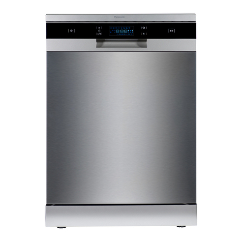
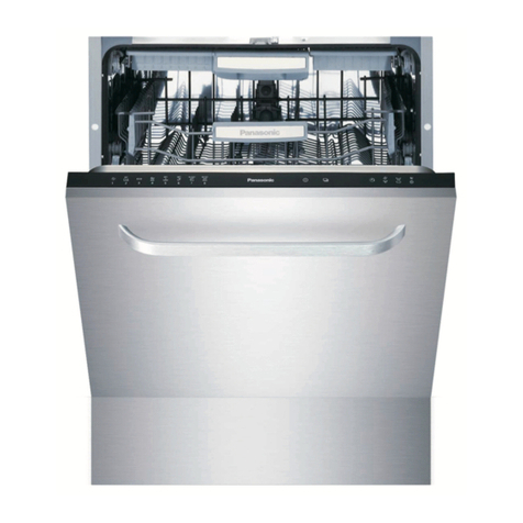
Panasonic NP-6R2MUQNZ-NZ User manual

© 2017 Panasonic Manufacturing Malaysia Berhad (6100-K).
Unauthorized copying and distribution is a violation of law.
ORDER NO. PMMA170535CE
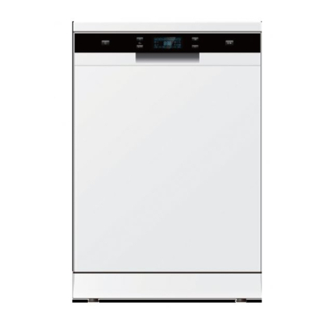
Stand-alone Dishwasher
Model No. NP-6R2MUQNZ-NZ
Destination: New Zealand

2
TABLE OF CONTENTS
PAGE PAGE
1Specifications------------------------------------------------------3
2ControlPanel-------------------------------------------------------4
3DisassemblyandAssemblyInstructions-----------------5
3.1. Access PCB -------------------------------------------------5
3.1.1. Removing the protecting box -----------------------5
3.2. Access inlet valve ------------------------------------------6
3.3. Access drain pump ----------------------------------------7
3.4. Access heater-----------------------------------------------8
3.5. Access Washing Pump -----------------------------------9
3.6. Access NTC -------------------------------------------------9
3.7. Access Flowmeter -----------------------------------------9
3.8. Access Safety Hose ------------------------------------- 10
3.9. Access Diverter Valve----------------------------------- 10
4BlockDiagram--------------------------------------------------- 11
4.1. Water Circuit----------------------------------------------- 11
5Troubleshooting------------------------------------------------- 13
5.1. Location----------------------------------------------------- 13
5.2. PCB---------------------------------------------------------- 15
5.2.1. View of PCB ------------------------------------------ 15
5.2.2. Description -------------------------------------------- 16
5.3. Inlet valve -------------------------------------------------- 16
5.3.1. Working Principle ------------------------------------ 16
5.3.2. Possible cause of Malfunction ------------------- 16
5.3.3. Technical data ---------------------------------------- 17
5.3.4. Inspect inlet valve ----------------------------------- 17
5.4. Drain Pump ------------------------------------------------ 18
5.4.1. Working Principle------------------------------------ 18
5.4.2. Possible cause of Malfunction ------------------- 18
5.4.3. Technical data ---------------------------------------- 18
5.4.4. Inspect drain pump---------------------------------- 19
5.5. Heater------------------------------------------------------- 20
5.5.1. Technical data ---------------------------------------- 20
5.5.2. Possible cause of Malfunction ------------------- 20
5.5.3. Inspect heater ---------------------------------------- 20
5.6. Washing Pump-------------------------------------------- 21
5.6.1. Possible cause of Malfunction ------------------- 21
5.6.2. Technical data ---------------------------------------- 21
5.6.3. Inspect Washing Pump ---------------------------- 22
5.7. Pressure Switch ------------------------------------------ 23
5.7.1. Working Principle------------------------------------ 23
5.8. NTC---------------------------------------------------------- 24
5.8.1. Working Principle------------------------------------ 24
5.8.2. Inspect NTC ------------------------------------------ 25
5.9. Flowmeter -------------------------------------------------- 26
5.9.1. Working Principle------------------------------------ 26
5.9.2. Inspect Flowmeter----------------------------------- 27
5.10. Safety Hose------------------------------------------------ 28
5.10.1. Location of Safety Hose --------------------------- 28
5.10.2. Working Principle------------------------------------ 28
5.10.3. Inspect Safety Hose -------------------------------- 29
5.11. Diverter Valve --------------------------------------------- 29
5.11.1. Work Principle ---------------------------------------- 29
5.12. Error code-------------------------------------------------- 29
5.12.1. How to know which error code has
occurred ----------------------------------------------- 29
5.12.2. Attention ----------------------------------------------- 30
5.12.3. Error code symptom -------------------------------- 31
5.13. Inspection -------------------------------------------------- 32
5.13.1. E1 tree ------------------------------------------------- 32
5.13.2. E3 tree ------------------------------------------------- 33
5.13.3. E4 tree ------------------------------------------------- 34
5.13.4. E6 & E7 tree------------------------------------------ 35
5.14. Troubleshooting ------------------------------------------ 36
6TestMethod------------------------------------------------------ 41
6.1. Test Program---------------------------------------------- 41
6.2. How to activate Test program ------------------------ 41
6.3. Procedure-------------------------------------------------- 42
7ExplodedView--------------------------------------------------- 43
8ReplacementPartList---------------------------------------- 51
8.1. Part List ---------------------------------------------------- 51
8.2. Packing List ----------------------------------------------- 52
3
1Specifications
Model NP-6R2MUQNZ
Power Source 220 - 240 V~
Wattage 1760 ~ 2100 W
Frequency 50 Hz
Water Pressure 0.04 - 1.0 MPa
Capacity 12 Settings
Dimensions (L ×W ×H) Approx. 600 mm ×600 mm ×850 mm
Nett Weight Approx. 48 kg

4
2ControlPanel
1. ON/OFF button:
To turn ON/OFF the power supply.
2. Time Delay button:
Press the button to delay. User can delay the washing time from
1 to 24 hours.
3. Child Lock:
Press the two buttons (2 and 4) simultaneously to lock/unlock the
programme. All button will not function after activated the Child
Lock unless it is unlocked.
4. Extra Dry Indicator:
Only Intensive, Heavy, ECO, Glass have this function.
5. Main Display: To show the remaining time and the state (running
state, delay time, and such).
Delay Time, Remain Time, or Error Codes indicator
Water Supply indicator
Indicates when shortage of water supply.
Extra Dry indicator
6. Programme indicators: To show which programme has been
chosen.
7. Programme Selection button:
Press the button to select appropriate programme.
8. Other indicators:
Rinse Aid indicator
Indicates when the dispenser needs to be refilled.
Complete Wash indicator
Child Lock indicator
9. Start/Pause button:
To pause the washingprogramme when the Dishwasher is
working or pause the selected washing
programme.

5
3 Disassembly and Assembly Instructions
3.1. Access PCB
3.1.1. Removing the protecting box
The PCB can be removed from the protecting box in the bottom of machine.
1. Disconnect power supply.
2. Take out cutlery basket, basket and filter system.
3. Open the cover of bottom board.
4. Remove the screws for fixing protecting box and open the protecting box cap.
5. Disconnect the connector form PCB.
6. Remove the screws securing the PCB to control panel.
7. Remove the PCB.
8. Reverse the above procedure to install.

6
3.2. Access inlet valve
1. Disconnect power.
2. Remove the water inlet hose. (Note : Be careful of remain water drop.)
3. Remove the cover of the bottom board.
4. Disconnect the 2 terminal lugs from the inlet valve.
5. Pull out the valve a little then turn it in anti-clockwise direction it to take it off.
6. Remove the clamp and disconnect the inlet hose (to air breaker) from the water valve.
7. Reverse above procedures to install.

7
3.3. Access drain pump
1. Drain off the water in the dishwasher, and disconnect the power supply.
(Note : Make sure to remove remained water in the dishwasher. If not, wet the floor.)
2. Loosen the hooks, and then remove bottom board.(Note:You should first loosen the top hooks, then the left and right hooks.
and be care do not break the hook.)
3. Label and disconnect the two terminal lugs from the drain pump.
4. Turn the drain pump in anti-clockwise direction to take it off.
5. Reverse the above procedure to install.

8
3.4. Access heater
1. Drain off the water in the dishwasher, and disconnect the power supply.
(Note : Make sure to remove remained water in the dishwasher. If not, wet the floor)
2. Remove bottom board.
3. Label and disconnect the terminals.
4. Remove the 3 screws for fixing the heating element.
5. Reverse above procedures to install.

9
3.5. Access Washing Pump
1. Disconnect power.
2. Remove bottom board.
3. Label and disconnect the 2 terminals to the motor wire connector.
4. Remove the clamp fastening the interconnect hose to the sump.
Caution: The clamp is easily damaged during removal and can’t be reused. Replace the old clamp with a new universal
clamp.
5. Disconnect the ground wire from the wash pump motor assembly.
6. Remove the motor pump assembly from the dishwasher.
7. Reverse above procedures to install.
3.6. Access NTC
1. Remove bottom board.
2. Remove two screws securing the NTC to sump (shown in above picture).
3. Take out NTC.
4. Reverse the above procedure to install.
3.7. Access Flowmeter
1. Remove the baseboard, top panel and left side panel.
2. Remove the plastic nut inside tub, which secures the air breaker to tub.(Because flowmeter is integrated into air breaker,
replace air breaker if flowmeter has failure.)
3. Disconnect the wire and remove clamp fastening hose to air breaker.
4. Take out air breaker.
5. Reverse the above procedure to install.

10
3.8. Access Safety Hose
1. Remove baseboard, side baseboard, top panel and left side panel.
2. Remove clamp, cut the bound belt and disconnect the wire connector. Then the Inlet hose cane pulled out.
3. Reverse the above procedure to assemble.
Mechanical Aquastop hose is connected to appliance just as universal water inlet hose.
3.9. Access Diverter Valve
1. Disconnect power.
2. Remove bottom board.
3. Label and disconnect the 4 terminals.
4. Remove 1 screw fastening the diverter valve to sump.
5. Contrarotate the diverter valve to take it off.
6. Reverse the above procedure to install.

11
4BlockDiagram
4.1. Water Circuit

12
Process of water inlet (indicated by magenta route)
In this process, regeneration water route is cut off, main water route is open. The water in the main water route is softened when
pass through the softener, and then enter in the tub. During this phase, some of inlet water will be stored in the air breaker to be
regenerating water.
Process of cycle washing (indicated by blue route)
Cycle washing action is driven by washing pump motor. Water can obtain the power during it passing through the working washing
pump, then be pumped into spray arm, pass from spray arm nozzles, over the dishes, into sump ,where connect to washing pump,
and to get in the next water cycle.

13
5Troubleshooting
5.1. Location

14
1. Ensure there is no wire clamped by PCB Casing after you closed the PCB Box.
2. Ensure the foam is already insert into the overflow assembly.
3. Ensure all terminals is inserted firmly.

15
4. Ensure the switch is inserted as the condition below:
5.2. PCB
Printed Circuit Board is the control center of dishwasher, which receive and process signal from components, send order to
components and deal with the feedback information, etc.
5.2.1. View of PCB

16
5.2.2. Description
5.3. Inlet valve
5.3.1. Working Principle
The inlet valve is electromagnetic valve that decide whether water enter or not. Valves are normally closed. Each time the appliance
requires water, the controller will convey an electric signal to the coils to open the valves.
The inlet valve consist of electric coil, valve body, valve pole, filter etc.
In a word, the electromagnetic valve can act to allow water enter into machine, when it receive the order given by controller.
5.3.2. Possible cause of Malfunction
1. The valve coil is broken, so the valve can’t open. It will cause the E1 error.
2. The filter is jammed, so water can’t enter. It will cause the E1 error.
3. The connector is loose, so the valve can’t open. It will cause the E1 error.
4. The valve pole is rusted or locked by dreg, so the valve can’t open or close. It will cause the E1 or E4 error.
Mark Function
HEAT Output for Heating Element
ACL Input of line
ACN Input of neutral
EV-L Input of inlet valve
RE Thermister
ML Washing Pump
PS Drain Pump
D/ED Dispenser
EV1 Inlet valve
EV2 Softener
EV3 Halfload Valve
ISS Salt detect
ISB Rinse detect
IAQS Overflow detect
FM Flowmeter
FAN Fan

17
5.3.3. Technical data
5.3.4. Inspect inlet valve
5.3.4.1. Check electric part
1. Open the protecting box and take out the PCB;
2. With the door closed, unplug the CON3 and ACN wires, then use the multi-meter Ωshelf to measure resistance between the
blue wire (EV1) and the blue wire (ACN), the normal resistance is about 3.4KΩto 4.4KΩ.
3. If the measured resistance is not correct, it means the valve coil is broken or the connector is loose. In this case, we should
check the connection first. If the problem hasn’t been solved by re-connection, we should replace the valve.
4. If the resistance is OK, we need to inspect the valve body.
5.3.4.2. Check machine part
1. If the electric part is OK, we need to check the machine part.
2. Check the valve filter. if the valve filter is blocked, we need clear the residues.
3. If the valve filter is clear and the valve can’t inlet water, check whether valve can act or not. If it isn’t, we need replace the
valve.
4. If the water is continue entering, we need replace the valve.
Nominal voltage 220-240VAC
Frequency 50/60Hz
Resistance Approx: 3.4 - 4.4kΩ
Work duty 100%ED T25
3min/5min T60
Flux 2.5L/min 15%
Power 5W
Work Pressure 0.04 - 1MPa

18
5.4. Drain Pump
5.4.1. Working Principle
Drain pump consists of electrical motor, impeller, inlet and outlet.
Drain pump is a kind of pump driven by permanent magnet synchronous motor. The rotor is made with permanent magnet material,
the running inertia of rotor is very small, the stator consist of silicon steel stack and coil. When the drain pump is on power, the rotor
will be very easy to start.
5.4.2. Possible cause of Malfunction
1. The motor coil is broken, so the drain pump can’t work. It will cause the E2 , E4 or E1 error.
2. The magnetism of motor rotor is weak, so drain pump cannot work. It will cause the E2, E4 or E1 error.
3. The connector is loose, so the drain pump can’t work. It will cause the E2, E4 or E1 error.
4. The rotor is locked by residues, so the drain can’t work . It will cause the E2, E4 or E1 error.
5. The drain pump assembly rack is loose, it will cause noise.
6. The non-return valve is bad, the remain water is too much.
Explanatory notes: failure of drain pump may cause E1, because
5.4.3. Technical data
Nominal voltage 220-240VAC
Frequency 50Hz
Resistance 167 10%kΩ
Delivery height 1M
Delivery performance 17l/min(230VAC)

19
5.4.4. Inspect drain pump
5.4.4.1. Check the electric part
1. Open the protecting box and take out the PCB.
2. With the door closed,unplug the CON3 and ACN wires, then use the multi-meter Ωshelf to measure the red wire (PS) and
blue wire (ACN), the normal resistance is about 150Ωto 190Ω.
3. If the measured resistance is not correct, it means the pump coil is broken or connector is loose. In this case, we should check
the connection first. If the problem hasn’t been solved by re-connection, we should replace the drain pump.
4. If the resistance is OK, but it also can’t work, maybe the magnetism is too weak, so we need to replace the drain pump.
5.4.4.2. Check the machine part
1. If the electric part is OK, we need to check the machine part.
2. Remove bottom board.
3. If the non-return valve is wrongly assembled, the tub will remain much water. We need to re-assemble the non-return valve.
4. If the drain pump is working, but no water drain out or just a little. We should check the drain hose or drain body.

20
5.5. Heater
5.5.1. Technical data
5.5.2. Possible cause of Malfunction
1. The heater coil is broken, so the heater cannot work. It will cause the E3 error.
2. The Fuse is active, so the heater cannot work. It will cause the E3 error.
3. The connector is loose, so the heater cannot work. It will cause the E3 error.
5.5.3. Inspect heater
1. Remove bottom board.
2. With the door closed,use the multi-meter Ωshelf to measure resistance between the two terminals shown in above right
picture, the resistance is about 29Ωto 31Ω.
3. If the measured resistance is not correct, it means the heater coil or the thermostat is broken, we should replace the heating
element or the thermostat.
Nominal voltage 230VAC
Rating power 1800W
Resistance 29.4 10%kΩ
Fuse 167°C
Table of contents
Other Panasonic Dishwasher manuals

Panasonic
Panasonic NP-6R2MUQNZ User manual

Panasonic
Panasonic NP-B6V2FTNZ Operating instructions

Panasonic
Panasonic NP-6F2MUQNZ-NZ User manual

Panasonic
Panasonic NP-B6M1 Operating instructions

Panasonic
Panasonic NP-B6V1 Operating instructions

Panasonic
Panasonic NP-TH1WEVN User manual

Panasonic
Panasonic NP-B6M1FIGB User manual

Panasonic
Panasonic NP-TH1HK User manual

Panasonic
Panasonic NP-B6M2FTNZ Operating instructions

Panasonic
Panasonic NP-6F1MLQ User manual