manuals.online logo
Brands
  1. Home
  2. •
  3. Brands
  4. •
  5. Panasonic
  6. •
  7. DVR
  8. •
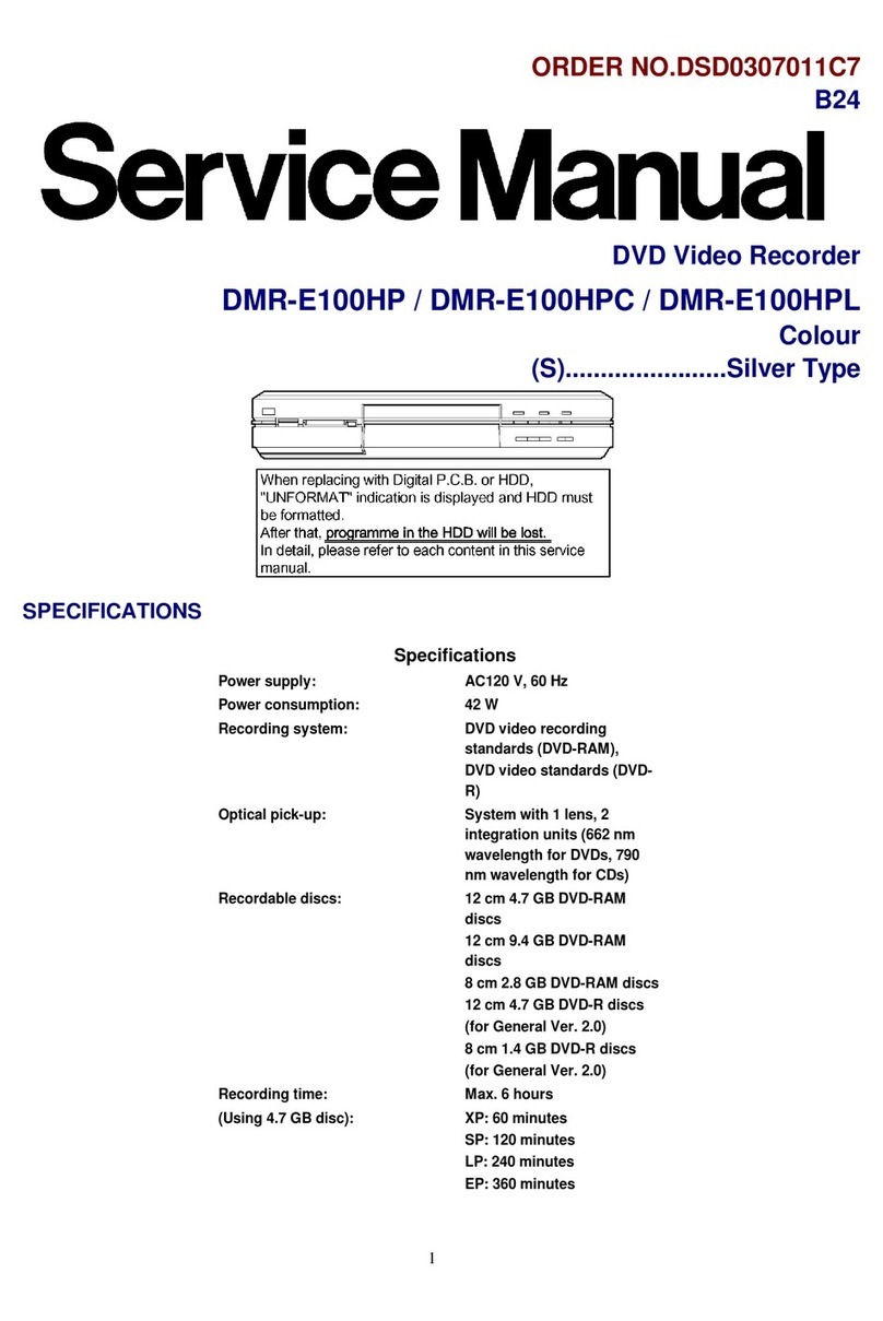
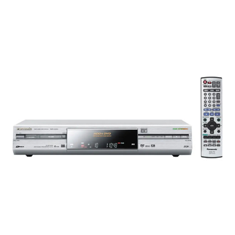
  9. Panasonic DMR-EH50EB User manual

Panasonic DMR-EH50EB User manual

ORDERNO.DSD0503040C2
DVDVideo Recorder
DMR-EH50EB / DMR-EH50EG / DMR-EH50EP / DMR-EH52EG
Vol.1
Colour
(K).......................Black Type
(S).......................Silver Type
SPECIFICATIONS
1
2
3
2005 Matsushita ElectricIndustrial CO., Ltd. All rights reserved.
Unauthorized copying and distribution isaviolation of law.
1. Safety precautions
1.1. General guidelines
1. When servicing, observe the original lead dress. Ifashort circuit
isfound, replace all parts which have been overheated or
damaged bythe short circuit.
2. After servicing, see to itthat all the protective devices such as
insulation barriers, insulation papers shields are properly
installed.
3. After servicing, make the following leakage current checks to
prevent the customer from being exposed to shock hazards.
1.1.1. Leakage current coldcheck
1. Unplug the AC cord and connect ajumper between the two
prongs on the plug.
2. Measure the resistance value, with an ohmmeter, between the
jumpered AC plug and each exposed metalliccabinet part on the
equipment such as screwheads, connectors, control shafts, etc.
4
When the exposed metallicpart has areturn path to the chassis,
the reading shouldbe between 1M and 5.2M . / When the
exposed metal does not have areturn path to the chassis, the
reading must be . Figure 1
1.1.2. Leakage current hot check / (See Figure 1 .)
1. Plug the AC cord directlyinto the AC outlet. Donot use an
isolation transformer for thischeck.
2. Connect a1.5k , 10 watts resistor, inparallel with a0.15 F
capacitors, between each exposed metallicpart on the set and a
good earth ground such as awater pipe, as shownin Figure 1.
3. Use an AC voltmeter, with 1000 ohms/voltor more sensitivity, to
measure the potential across the resistor.
4. Check each exposed metallicpart, and measure the voltage at
each point.
5. Reverse the AC plug inthe AC outlet and repeat each of the above
measurements.
6. The potential at anypoint shouldnot exceed 0.75 volts RMS. A
leakage current tester (Simpson Model 229 or equivalent) maybe
used to make the hot checks, leakage current must not exceed 1/2
milliampere. Incase ameasurement isoutside of the limits
specified, there isapossibilityof ashock hazard, and the
equipment shouldbe repaired and rechecked before itisreturned
to the customer.
2. Prevention of Electrostatic Discharge (ESD) to
Electrostatic Sensitive (ES) Devices
Some semiconductor(solidstate) devices canbe damagedeasilybystatic electricity. Such
components commonlyare calledElectrostatic Sensitive (ES) Devices. Examples of typical ES
devices are integratedcircuits and some field-effect transistor-sand semiconductor"chip"
5
components. The following techniques shouldbe usedtohelpreduce the incidence of
component damage causedbyelectrostatic discharge (ESD).
1. Immediatelybefore handling anysemiconductor component or
semiconductor-equipped assembly, drainoff anyESDon your
bodybytouching aknownearth ground. Alternatively, obtainand
wear acommerciallyavailabledischarging ESDwrist strap, which
shouldbe removed for potential shock reasons prior to applying
power to the unitunder test.
2. After removing an electrical assemblyequipped with ES devices,
place the assemblyon aconductive surface such as aluminum
foil, to prevent electrostaticcharge buildup or exposure of the
assembly.
3. Use onlyagrounded-tipsoldering iron to solder or unsolder ES
devices.
4. Use onlyan anti-staticsolder removal device. Some solder
removal devices not classified as "anti-static(ESDprotected)"
can generate electrical charge sufficient to damage ES devices.
5. Donot use freon-propelled chemicals. These can generate
electrical charges sufficient to damage ES devices.
6. Donot remove areplacement ES device from its protective
package until immediatelybefore you are readyto install it. (Most
replacement ES devices are packaged with leads electrically
shorted together byconductive foam, aluminum foil or
comparableconductive material).
7. Immediatelybefore removing the protective material from the
leads of areplacement ES device, touch the protective material to
the chassisor circuitassemblyinto which the device will be
installed.
Caution
Besure no power isapplied to the chassisor circuit, and observe
all other safetyprecautions.
8. Minimize bodilymotions when handling unpackaged replacement
ES devices. (Otherwise hamless motion such as the brushing
together of your clothes fabricor the lifting of your foot from a
carpeted floor can generate staticelectricitysufficient to damage
6
an ES device).
3. Precaution of Laser Diode
4. Handling the Lead-free Solder
4.1. About lead free solder (PbF)
Distinction of PbF P.C.B.:
P.C.B.s (manufactured) using leadfree solderwill have a PbF stampon the P.C.B.
Caution:
-Pb free solder has ahigher melting point than standard solder;
Typicallythe melting point is50 -70°F (30 -40°C)higher. Please
use ahigh temperature soldering iron. Incase of the soldering
iron with temperature control, please set itto 700 ± 20°F (370 ±
10°C).
-Pb free solder will tend to splash when heated too high (about
1100°F/600°C).
7
-When soldering or unsoldering, please completelyremove all of
the solder on the pins or solder area, and be sure to heat the
soldering points with the Pb free solder until itmelts enough.
5. Each Button
6. New Feature
6.1. Quick start function(REC)
1. General
Afew seconds after tuning on the unit,you can start recording
to DVD-RAM,HDD.
You can switch the operation of thisfunction (ON/OFF) on the
menu screen. .
2. Quick start(REC)principle
Inthe power-off at Quick start, onlypower supplies for video
IC,tuner and storage mediaare cut off.
When the RECbutton ispushed afew second after the
power button ispushed, Audioand Video data are stored in
DDR SDRAMbefore astorage media(DVD-RAMor HDD)
preparation.
*Preparation time DVD-RAM: Fabout 8seconds
HDD:about 18seconds
After astorage media(DVD-RAMor HDD)
preparation,Audioand Video data are transfer from DDR SDRAM
to the storage media.
8
7. Taking out the Disc from RAM-Drive Unit when the
Disc cannot be ejected by OPEN/CLOSE button
7.1. ForcibleDisc Eject
7.1.1. When the powercan be turned off.
1. Turn off the power and press [STOP] [CH UP] keyson the front
panel simultaneouslyfor 5seconds.
7.1.2. When the powercan not be turned off.
1. Press [POWER]keyon the front panel for over 10 seconds to turn
off the power forcibly, and press [STOP] [CH UP] keyson the front
panel simultaneouslyfor 5seconds.
9
7.2. When the ForcibleDisc Eject can not be done.
1. Turn off the power and pull out AC cord.
2. Remove the Top Case.
3. Remove the Front Panel.
4. Remove 4screwsand Upper Base Unitfrom DVD-RAMDrive.
5. Take out the disc and put the Opener Roller on fullyposition for
direction of Arrow.
6. Put the Upper Base Unitso that the Opener Roller isinserted into
the groove.
7. Check Opener Roller isseen through the Opener position
Checking Hole, and tighten 4screws.
10
8. Service Explorer
Confirm “RAM-Drive Last Error” inService Mode
Execute Service Mode
1. Press [REC], [CH UP] and [OPEN/CLOSE] simultaneouslyfor 5
seconds when P-off.
FL Display:
*After finishing display“(7). Factor of Drive Error occurring”,
press [0] [2] ~[1] [9] keysof the Remote Controller so that 19
memories can be displayed as maximum.
2. Press [4] [2] keysof remote controller.
11
Example of FL Display:
(1) ErrorNumberis displayedfor5 seconds.
(2) Time whenthe errorhas occurredis displayedfor5 seconds.
(3) Last Drive Error(1/2) is displayedfor5 seconds.
(4) Last Drive Error(2/2) is displayedfor5 seconds.
(5) Erroroccurring Disc type is displayedfor5 seconds.
(6) Disc Maker's ID is displayedfor5 seconds.
Example of Disc Maker's ID:
DVD-R Disc
No. FL Display(Disc
Maker's ID) Disc Maker Country
1MEI Panasonic Japan
2 PVC Pioneer Japan
3 MCC Mitsubishi Chemical
Corporation Japan
4TDK TDK Japan
5 MXL Maxell Japan
6 MCI MITUI CHEMICALS Japan
7 JVC VictorJVC Japan
8TAIYOYUDEN Taiyoyuden Japan
TYG
9 GSC Giga Storage Taiwan
10 PRODISC Prodisc Taiwan
11 PRINCO PRINCO Taiwan
12 RITEK RITEK Taiwan
13 OPTDISC OPTDISC Taiwan
14 LEAD DATA LEAD DATA Taiwan
12
No. FL Display(Disc
Maker's ID) Disc Maker Country
15 CMC CMC Taiwan
16 AUVISTAR AUVISTAR Taiwan
17 ACER Acer Taiwan
18 VIVASTAR VIVASTAR Switzerland
19 LGE LG Electronics Korea
DVD-RAM Disc
No. FL Display(Disc
Maker's ID) Disc Maker Country
1MEI Panasonic
2 MATSUSHITA Panasonic Japan
3 MXL Maxell Japan
4 PRODISC Prodisc Taiwan
5 OPTDISC OPTDISC Taiwan
6 CMC CMC Taiwan
*Since andisplayis arbitrarilyset up bythe disk producerside, the above-mentioneddisplay
maybe changed.
Please make it reference as anexample of a display.
(7) Factorof Drive Erroroccurring is left displayed
ErrorOccurring Disc Type
FL Display Disc Type
00 DVD-ROM/Video
01 Audio-CD
02 2.6GB DVD-RAM
03 4.7GB DVD-RAM
04 DVD-R
ErrorOccurring Disc State
13
9. Self-Diagnosis and Special Mode Setting
9.1. Self-DiagnosisFunctions
Self-Diagnosis Function provides information forerrors toservice personnel by“Self-Diagnosis
Display” whenanyerrorhas occurred.
U**, H** and F** are storedinmemoryand held.
You cancheck latest errorcode bytransmitting [0] [1] of Remote ControllerinService Mode.
Automatic Displayon FL will be cancelledwhenthe poweris turnedoff orAC input is turnedoff
during self-diagnosis displayis ON.
Error
Code Diagnosis contents Description Monitor
Display Automatic
FL
U30 Remote control code
error Displayappears whenmainunit
and remote controllercodes are
not matched.
Nodisplay
“*” is remote
controller
code of the
main
Displayfor5
seconds.
U59 Abnormal inner
temperature detected Displayappears whenthe drive
temperature exceeds 70°C.
The poweris turnedoff forcibly.
For30 minutes afterthis, all key
entries are disabled. (Fanmotor
operates at the highest speedfor
the first 5 minutes. Forthe
remaining 25 minutes, fanmotor
is alsostopped.) The event is
savedinmemoryas well.
Nodisplay
“U59 is
displayed
minutes.
U99 Hang-up Displayedwhencommunication
errorhas occurredbetweenMain
microprocessorand Timer
microprocessor.
Nodisplay
Displayedis
left
[POWER] key
is
H19 Inoperative fanmotor Wheninoperative fanmotoris
detectedafterpoweredon, the
poweris turnedoff automatically.
The event is savedinmemory.
Nodisplay Nodisplay
14
Error
Code Diagnosis contents Description Monitor
Display Automatic
FL
F00 Noerrorinformation Initial setting forerrorcode in
memory
(Errorcode Initialization is
possible witherrorcode
initialization and mainunit
initialization.)
Nodisplay Nodisplay
F58 Drive hardware error Whendrive unit erroris detected,
the event is savedinmemory. Nodisplay Nodisplay
F34 Initialization error
whenmain
microprocessoris
startedup forprogram
recording
Wheninitialization erroris
detectedafterstarting up main
microprocessorforprogram
recording, the poweris turned
off automatically.
The event is savedinmemory.
Nodisplay Nodisplay
UNSUPPORT
Unsupporteddisc
error *Anunsupportedformat disc
was played, although the drive
starts normally.
*The data format is not
supported, although the media
type is supported.
*Exceptionallyincase of the disc
is dirty.
“This disc is
incompatible.”
Displayfor5
seconds.
NO
READ Disc readerror *A disc is flawedordirty.
*A poorqualityfailedtostart.
*The track information couldnot
be read.
“Cannot read.
Please check
the disc.”
Displayfor5
seconds.
HARD
ERR Drive error The drive detecteda harderror. “DVD drive
error.”
Displayfor5
seconds.
SELF
CHECK Restoration operation Since the powercordfell out
during a powerfailure or
operation, it is underrestoration
operation.
*It will OK, if a display
disappears automatically. If a
displaydoes not disappear, there
is the possibilitythat defective
Digital P.C.B. / RAM drive.
Nodisplay
Full
Program32 programs are
alreadyset. 32 programs are alreadyset. Nodisplay
15
Error
Code Diagnosis contents Description Monitor
Display Automatic
FL
UNFORMAT
Unformatteddisc error You have insertedan
unformattedDVD-RAM orDVD-
RW that is unformattedor
recordedon otherequipment.
PLEASE
WAIT Unit is intermination
process Unit is intermination process
now.
“BYE” is displayedand power
will be turnedoff.
Incase “Quick Start” of setup
menu is ON, it is displayedin
restoration operation forAC off.
Nodisplay
9.2. Special Modes Setting
Item FL display Key
operation
Mode name Description Front
Key
TESTMode *All the mainunit's parameters
(include tuner) are initialized. Press [STOP], [
CH
and [OPEN/
CLOSE]
simultaneously
seconds when
power
off.
Rating password The audiovisual level setting
passwordis initializedto“Level
8”.
Openthe tray,
and
[REC] and [
PLAY]
simultaneously
seconds.
NOTE:
Drive should
be
toDVD.
Service Mode Setting everykind of modes for
servicing.
*Details are describedin“9.3.
Service Mode”.
Whenthe
power
press [CH UP],
[
CLOSE] and [
REC]
simultaneously
seconds.
16
Item FL display Key
operation
Mode name Description Front
Key
Forceddisc eject Removing a disc that cannot be
ejected.
The traywill openand unit will
shift toP-off mode.
*WhenTimerREC is ON orEXT-
LINK is ON, execute " Forced
disc eject " afterreleasing Timer
REC orEXT-LINK.
*This command is not effective
during "Childlock" is ON.
While Demonstration Lock is
being set, this Forceddisc eject
function is not accepted.
The displaybefore
execution leaves. Whenthe
power
press [STOP]
and
keys
simultaneously
seconds.
Childlock/unlock Set orrelease “ChildLock”. Press [ENTER]
and
[RETURN] by
remote
controller
simultaneously
until [X-HOLD]
is
displayed.
NTSC/PAL
systemselect To switchPAL/NTSC alternately. The displaybefore
execution leaves. While the
power
E mode), press
[
and [OPEN/
CLOSE]
simultaneously
seconds.
Forcedpower-off Whenthe powerbutton is not
effective while poweris ON, turn
off the powerforcibly.
*WhenTimerREC is ON orEXT-
LINK is ON, execute “Forced
Power-off” afterreleasing Timer
REC orEXT-LINK.
DisplayinP-off mode. Press [Power]
key
than10
seconds.
17
Item FL display Key
operation
Mode name Description Front
Key
Aging Perform sequence of modes as *
Aging Description shownbelow
continually.
Displayfollowing the then
mode. Whenthe
power
press [STOP], [
POWER]
and [OPEN/
CLOSE]
simultaneously
seconds and
less
seconds.
NOTE1:
If Unit has not
turned
Aging mode
by
operations
shown
execute TEST
MODE
and re-execute
operation
shownabove.
(*All the main
unit’s
parameters
include
are initialized
by
mode.)
NOTE2:
If the unit has
hung
because of
pressing
forover10
seconds,
turnoff the
power,
execute this
command.
*When
releasing
mode, press [
POWER]
key.
Aging Contents (Example):
18
Item FL display Key
operation
Mode name Description Front
Key
Demonstration
lock/unlock Ejection of the disc is prohibited.
The lock setting is effective until
unlocking the trayand not
releasedby“Mainunit
initialization” of service mode.
*Whenlock the tray.
“LOCK” is displayedfor3
seconds.
Whenthe
power
press [STOP]
and
[POWER] keys
simultaneously
seconds.
*Whenunlock the tray.
“UNLOCK” is displayed
for3 seconds.
Whenthe
power
press [STOP]
and
[POWER] keys
simultaneously
seconds.
*Whenpress OPEN/
CLOSE keywhile the tray
being locked.
Display“LOCK” for3
seconds.
Press [OPEN/
CLOSE]
while the tray
being
locked.
ATP re-execution Re-execute ATP. Displayat ATP executing. Whenthe
power
E mode), press
[
and [CH
DOWN]
simultaneously
seconds.
Progressive
initialization The progressive setting is
initializedtoInterlace. The displaybefore
execution leaves. Whenthe
power
E mode), press
[
and [PLAY]
simultaneously
seconds.
9.3. Service Modes
Service mode setting: While the poweris off, press REC, CH UP and OPEN / CLOSE
simultaneouslyforfive seconds.
19
Item FL display Key
operation
Mode name Description (Remote
controller
Release Items Itemof Service Mode executing
is cancelled. Press [0] [0] or
[
service mode.
ErrorCode
Display Last ErrorCode of U/H/Fheldby
Timeris displayedon FL.
*Details are describedin“9.1. Self
-Diagnosis Functions”.
Press [0] [1] in
service
mode
ROM Version
Display Region code, MAIN firm version,
TIMER firm version and DRIVE
firmware versions are displayed
on FL forfive seconds pereach
version inorder, but ROM
version will be left displayed.
‘’*’’ are version displays.
Press [0] [2] in
service
mode
White Picture
Output White picture is output as
component Output fromAV
Decoder.
*White picture
(Saturation rate : 100%)
*It is enable toswitchInterlace/
Progressive by“I/P switch: [1]
[4]”
*Initial mode is “Interlace”.
Press [1] [1] in
service
mode.
SwitchInterlace/
Progressive Press [1] [4] in
White
Picture Output
mode.
*I/P are
switched
alternately.
Magenta Picture
Output Magenta picture is output with
Component Output fromAV
Decoder.
*Magenta picture
(Saturation rate: 100%)
*It is enable toswitchInterlace/
Progressive by“I/P switch: [1]
[4]”
*Initial mode is “Interlace”.
Press [1] [2] in
service
mode.
SwitchInterlace/
Progressive Press [1] [4] in
Magenta
Picture Output
mode.
*I/P are
switched
alternately.
20

Other manuals for DMR-EH50EB

1

This manual suits for next models

3

Other Panasonic DVR manuals

Panasonic WJ-HD716 User manual

Panasonic

Panasonic WJ-HD716 User manual

Panasonic DMRHS2 - DVD RECORD.W/HD DRIV User manual

Panasonic

Panasonic DMRHS2 - DVD RECORD.W/HD DRIV User manual

Panasonic WJ-NV200K User manual

Panasonic

Panasonic WJ-NV200K User manual

Panasonic DMRHS2 - DVD RECORD.W/HD DRIV User manual

Panasonic

Panasonic DMRHS2 - DVD RECORD.W/HD DRIV User manual

Panasonic BB-HNP15A User manual

Panasonic

Panasonic BB-HNP15A User manual

Panasonic AG-CPD15P User manual

Panasonic

Panasonic AG-CPD15P User manual

Panasonic DMR-ES20EG User manual

Panasonic

Panasonic DMR-ES20EG User manual

Panasonic WJ-ND300A/10000V User manual

Panasonic

Panasonic WJ-ND300A/10000V User manual

Panasonic DMR-T3030 User manual

Panasonic

Panasonic DMR-T3030 User manual

Panasonic WJ-NV200 User manual

Panasonic

Panasonic WJ-NV200 User manual

Panasonic DMR-EH80VEG User manual

Panasonic

Panasonic DMR-EH80VEG User manual

Panasonic DMR-E60PP User manual

Panasonic

Panasonic DMR-E60PP User manual

Panasonic Diga DMR-E65 User manual

Panasonic

Panasonic Diga DMR-E65 User manual

Panasonic WJHD309 - DIGITAL DISK RECORDER User manual

Panasonic

Panasonic WJHD309 - DIGITAL DISK RECORDER User manual

Panasonic WJRT416 - 16CH DIGITAL RECORDER User manual

Panasonic

Panasonic WJRT416 - 16CH DIGITAL RECORDER User manual

Panasonic DMR-ES30VGN User manual

Panasonic

Panasonic DMR-ES30VGN User manual

Panasonic Diga DMR-E51 User manual

Panasonic

Panasonic Diga DMR-E51 User manual

Panasonic DIGA DMR-E85H User manual

Panasonic

Panasonic DIGA DMR-E85H User manual

Panasonic Diga DMR-ES10EB User manual

Panasonic

Panasonic Diga DMR-ES10EB User manual

Panasonic DMR-ES10PL User manual

Panasonic

Panasonic DMR-ES10PL User manual

Panasonic WJ-ND300A User manual

Panasonic

Panasonic WJ-ND300A User manual

Panasonic DMR-E85HP User manual

Panasonic

Panasonic DMR-E85HP User manual

Panasonic DMR-T3030 User manual

Panasonic

Panasonic DMR-T3030 User manual

Panasonic DMRE75VP User manual

Panasonic

Panasonic DMRE75VP User manual

Popular DVR manuals by other brands

Cabletech URZ0299 user manual

Cabletech

Cabletech URZ0299 user manual

Footprint Security H.264 user manual

Footprint Security

Footprint Security H.264 user manual

Aliveal USB WiGuard user manual

Aliveal

Aliveal USB WiGuard user manual

Jazz HDV146 instruction manual

Jazz

Jazz HDV146 instruction manual

Samsung SDE-500X user manual

Samsung

Samsung SDE-500X user manual

WebGate HD400H quick guide

WebGate

WebGate HD400H quick guide

Toshiba SD-1810 owner's manual

Toshiba

Toshiba SD-1810 owner's manual

Novus NVR-3304 user manual

Novus

Novus NVR-3304 user manual

JVC DR-MH30S instructions

JVC

JVC DR-MH30S instructions

Eclipse 4 Channel user manual

Eclipse

Eclipse 4 Channel user manual

globex GU-216 user manual

globex

globex GU-216 user manual

Eneo HDR-4004AM quick guide

Eneo

Eneo HDR-4004AM quick guide

Veilux VR-412D1 Operating instructions & user guide

Veilux

Veilux VR-412D1 Operating instructions & user guide

MSUN INDUSTRIAL HQ30 instruction manual

MSUN INDUSTRIAL

MSUN INDUSTRIAL HQ30 instruction manual

V-TAC VT-5127 Installation instruction

V-TAC

V-TAC VT-5127 Installation instruction

Hitachi HDR162 instruction manual

Hitachi

Hitachi HDR162 instruction manual

iCatch 4CH quick start guide

iCatch

iCatch 4CH quick start guide

WBOX Technologies 0E-4CHNVR1TB Step-by-step Guide/How-to

WBOX Technologies

WBOX Technologies 0E-4CHNVR1TB Step-by-step Guide/How-to

manuals.online logo
manuals.online logoBrands
  • About & Mission
  • Contact us
  • Privacy Policy
  • Terms and Conditions

Copyright 2025 Manuals.Online. All Rights Reserved.