HD9220/20 /21 /22 /23 /24
3-10
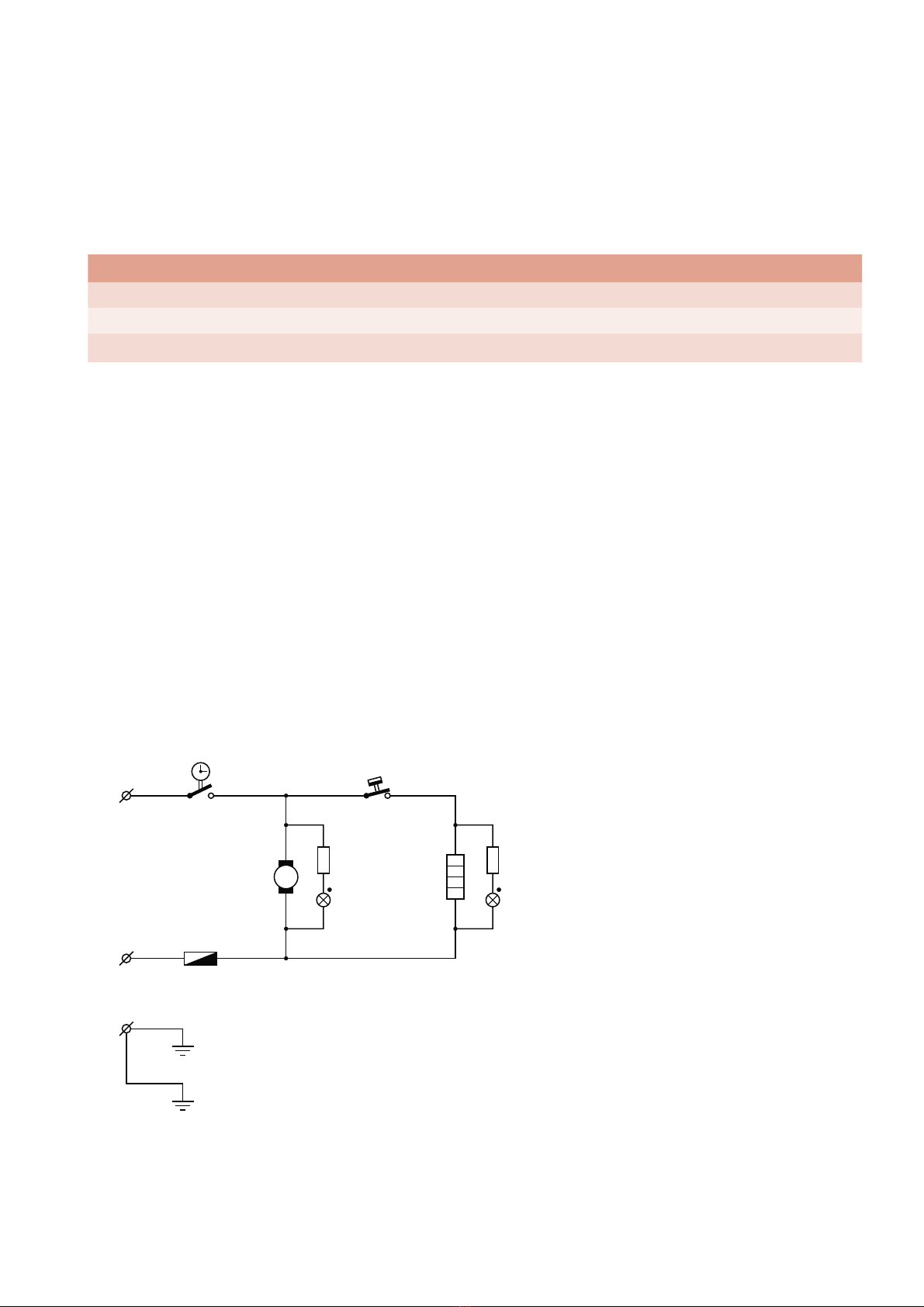
TROUBLE SHOOTING
Part/
System Test Possible deviation Analyses
Replace
(depending of
the analyses
outcome)
Timer Check if the green light is lit,
and if you can hear the timer
ticking
The green light is not lit
but the timer is ticking
Check the timer-switch and the
fuse with a multimeter
Timer/Fuse
The green light is lit but
the timer is not ticking
Timer is defective Timer
Thermostat Set the temperature at 80°C
and check if the heating
element is getting warm
(Check input power approx.
1425W)
The green light should be lit
and the orange light should
switch off after it reaches
80°C
Both green and orange
light are lit but there is no
heating
Check the heating element with
a multimeter
Heating element
If the green light is lit and
the orange light is off
Check the thermostat with a
multimeter
Thermostat
If both the green and
orange light are off
Check the timer and fuse with a
multimeter
Timer/Fuse
The orange light does not
switch off after reaching
approx. 80°C
Thermostat is defective Thermostat
Motor fan
assy
Set the timer and listen if the
motor is running
Motor is not running The fan is scraping the housing
turning it by hand (Switch off the
power when you do this test!)
Motor fan assy
The fan is not scraping the
housing turning it by hand
(Switch off the power when you
do this test!):
Check the motor fan assy, timer
and fuse with a multi meter
Motor fan assy /
Timer/Fuse
Heating
element
Check if the heating element
is getting warm
(Check input power approx.
1425W)
If the Orange light is on
and the heating element
does not heat
Check the heating element with
a multimeter
Heating element
If the heating element
does not heat and the
orange light is off
Check the timer, fuse and
thermostat with a multimeter
Timer/Fuse/
Thermostat
Thermal fuse Set the timer and check if
the green light is lit
Green light is not lit Check the timer and fuse with a
multimeter
Timer/Fuse