Panasonic MX-AC300 User manual
© 2007 Panasonic Home Appliances India Co., Ltd.
All rights reserved. Unauthorized copying and distri-
bution is a violation of law.
No.PHAI0712001CE
Super Mixer Grinder
Model No. MX-AC300
Model No. MX-AC220
Model No. MX-AC210
Color: Grey/Blue
Destination: India
TABLE OF CONTENTS
PAGE PAGE
1 Safety Precautions----------------------------------------------- 2
2 Specifications ----------------------------------------------------- 3
3 Location of Controls and Components ------------------- 4
3.1. Accessories/Parts Identification------------------------ 4
4 Troubleshooting Guide ----------------------------------------- 5
5 Disassembly and Assembly Instructions ---------------- 7
5.1. Rubber Cap, Connector U (lower)--------------------- 7
5.2. Bottom Plate ------------------------------------------------ 7
5.3. Power Cord U / Circuit Breaker ------------------------ 8
5.4. Switch Complete------------------------------------------- 9
5.5. Switch Complete B ---------------------------------------- 9
5.6. Motor Complete / Upper Body-------------------------10
5.7. Blender Jar Complete (Mill Cup Complete /
Chutney Jar Complete) ---------------------------------11
5.8. Lid C (Lid A)------------------------------------------------13
6 Wiring Connection Diagram ---------------------------------14
6.1. Wiring Diagram--------------------------------------------14
6.2. Electric Circuit ---------------------------------------------14
7 Exploded View and Replacement Parts List -----------15
7.1. Parts Location (MX-AC300)----------------------------15
7.2. Replacement parts list (MX-AC300) -----------------16
7.3. Parts Location (MX-AC220)----------------------------18
7.4. Replacement parts list (MX-AC220) -----------------19
7.5. Parts Location (MX-AC210)----------------------------21
7.6. Replacement parts list (MX-AC210) -----------------22
7.7. Packing Procedure ---------------------------------------24
2
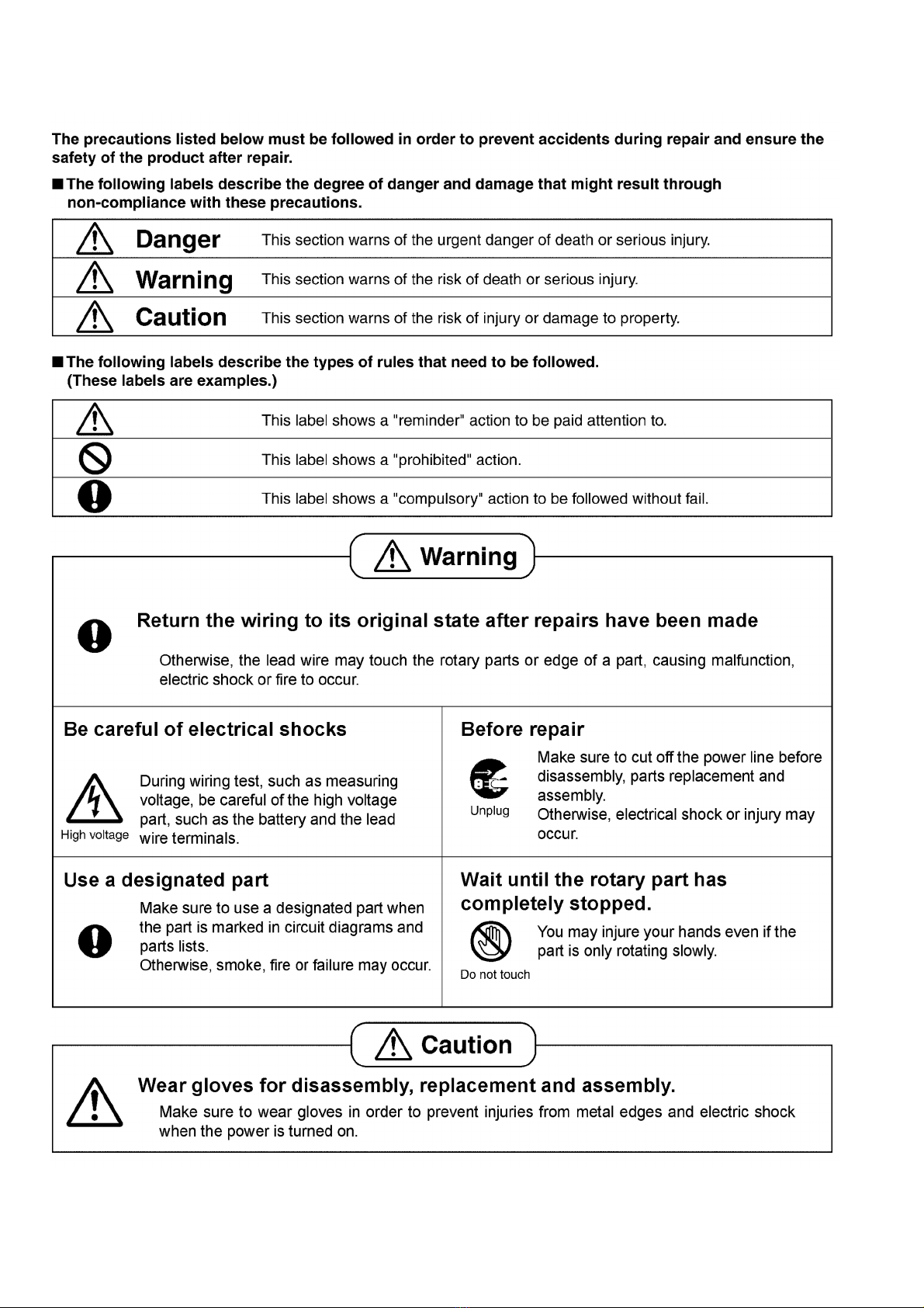
1 Safety Precautions

3
2 Specifications
Model No. MX-AC300 MX-AC220 MX-AC210
Power Supply 230V~50Hz
Power Consumption 550W
Protection Circuit Breaker
Rating 30 min
Material
Housing Plastic(ABS)
Jar Plastic(Polycarbonate) Not Available Plastic(Polycarbonate)
Mill Jar Stainless Steel Not Available
Chutney Jar Stainless Steel
Lid Plastic(Polycarbonate)
Blade Stainless Steel Hard Type
Speed Control 3 Speed with 1 Pulse & 1 Off Button(piano Type Buttons)
Capacity
Jar
Max.
1.0L(Wet only) Not Available 1.0L(Wet only)
Mill Jar 0.5L(Dry)/0.3L(Wet) Not Available
Chutney Jar 0.2L
Weight 4.6kg 3.9kg 3.9kg
Accessories Spatula,Whipping Plate
4
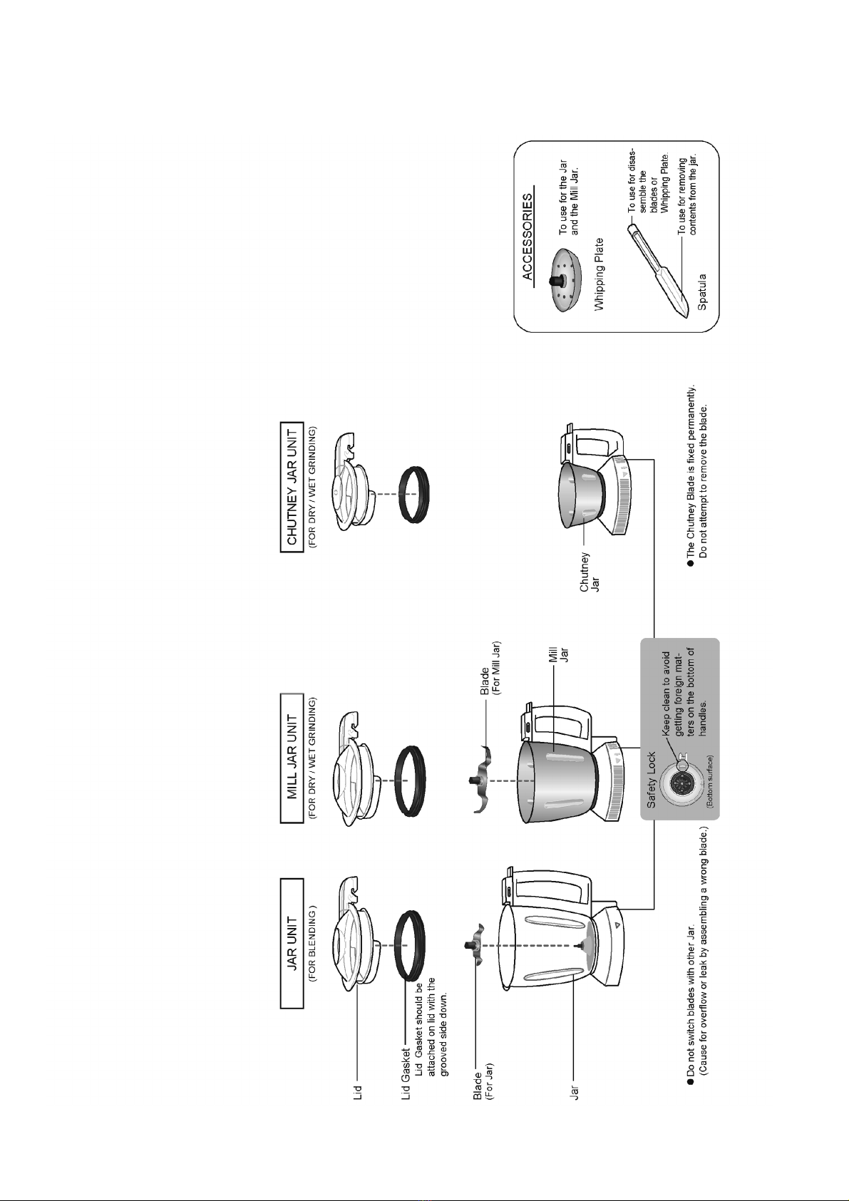
3 Location of Controls and Components
3.1. Accessories/Parts Identification

5
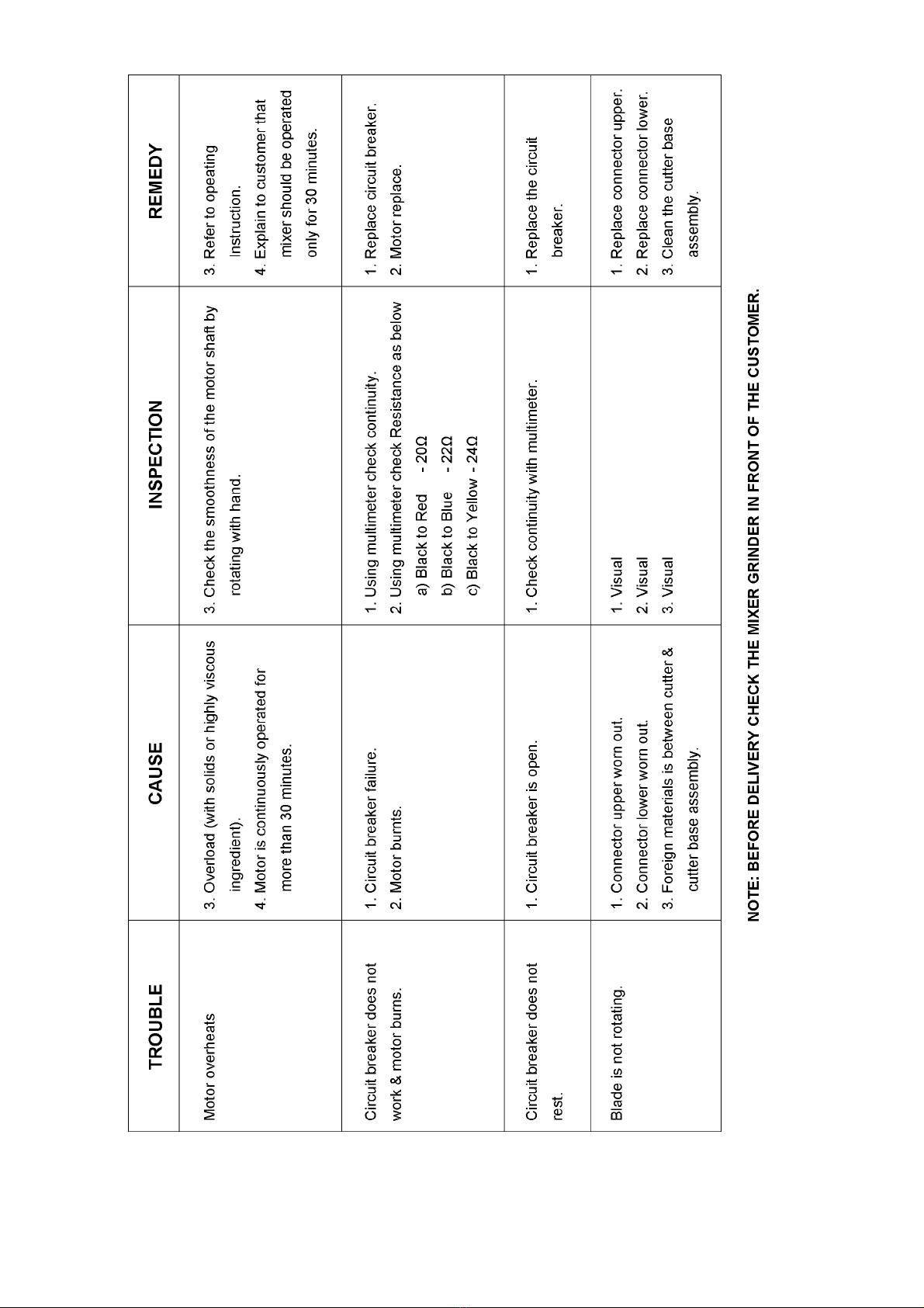
4 Troubleshooting Guide
6

7
5 Disassembly and Assembly Instructions
For assembly, refer to the Assembly Instructions, and perform the procedures in the opposite order of disassembly.
5.1. Rubber Cap, Connector U (lower)
1. Remove Rubber Cap
2. Turn the Nut clockwise, and remove it.
3. Pull out Connector U (lower) and remove Plate
Washer and Lock Washer.
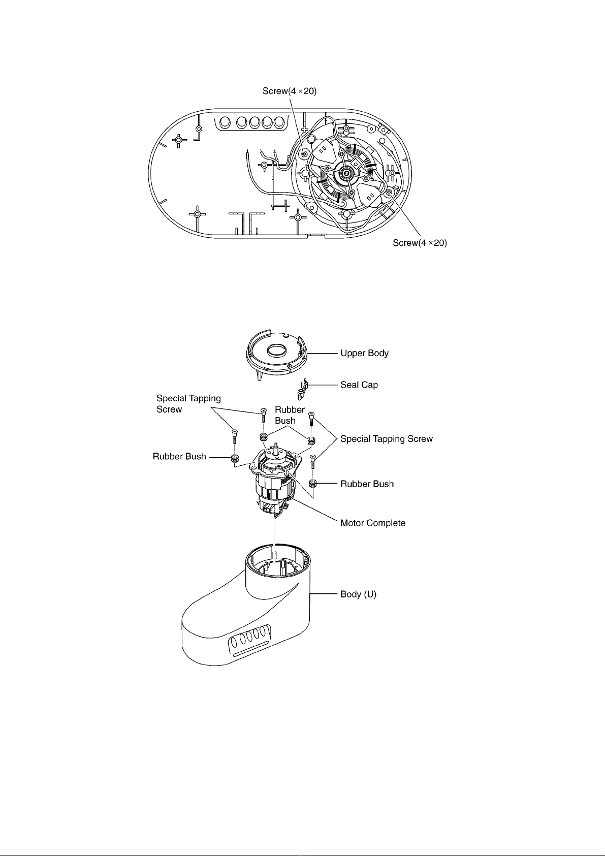
5.2. Bottom Plate
1. Remove the 6 Tapping Screws (4x20), and remove
the Bottom Plate.
2. Detach the Motor Cap and Foot from the Bottom
Plate.
8
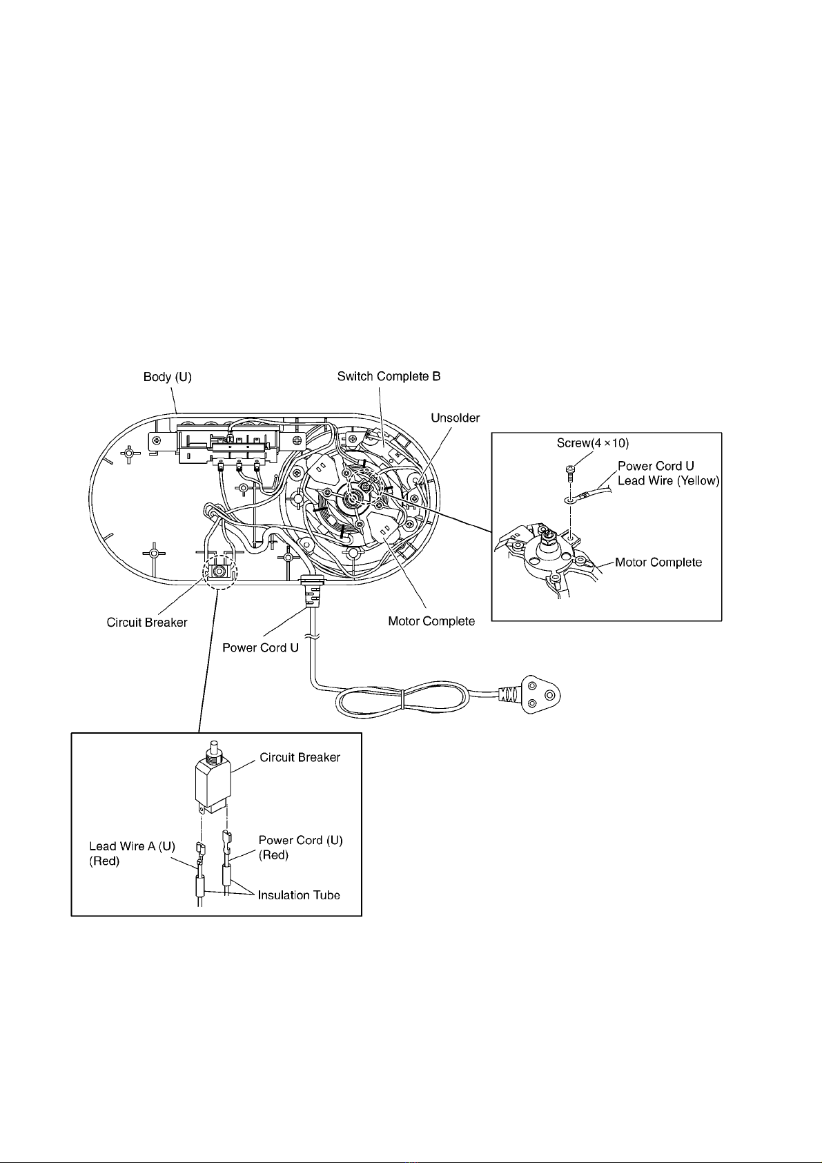
5.3. Power Cord U / Circuit Breaker
1. Remove the Screw (4x10) which fixes the Motor
Complete, and remove the Lead Wire (Yellow).
2. Move the 2 Insulation Tubes from the Circuit
Breaker, remove the faston terminals of Lead Wire
A (U) and Power Cord (U), and remove the Circuit
Breaker.
Assembly Instructions
Attach the Lead Wire to the Circuit Breaker, and
set Insulation Tubes firmly.
3. Melt the solder which fixes the Lead Wire (Black) on
Switch Complete B, and remove the Power Cord
(U).

9
5.4. Switch Complete
1. Remove the faston terminal of Lead Wire A (U).
2. Melt the solder and detach the Lead Wire Yellow,
Blue, Red from the Motor Complete.
3. Remove the Screw (4x20), and remove the Switch
Complete.
5.5. Switch Complete B
1. Melt the solder and detach the Lead Wire (Black)
from the Motor Complete.
2. Remove the Screws (4x20) and remove Switch
Complete B.
10
5.6. Motor Complete / Upper Body
1. Remove the 2 Screws (4x20)
2. Put the body upside-down and remove the Upper
Body.
3. Remove the 4 Special Tapping Screws, which fix
the Motor Complete, and remove the Motor Com-
plete.
Assembly Instructions
Add vaseline in 2 hole positions of Seal Cap
before assembling into the upper body.
Other manuals for MX-AC300
1
This manual suits for next models
2
Table of contents
Other Panasonic Grinder manuals

Panasonic
Panasonic EY46A2 User manual

Panasonic
Panasonic MX-AC555 User manual

Panasonic
Panasonic EY4640 User manual

Panasonic
Panasonic EY46A2 User manual

Panasonic
Panasonic EY46A2X57 User manual

Panasonic
Panasonic 46A2LJ User manual

Panasonic
Panasonic EY4640 User manual

Panasonic
Panasonic EY4640 User manual

Panasonic
Panasonic MX-AC400 User manual

Panasonic
Panasonic EY4640 User manual


