Panasonic SJ-MR220 User manual

ORDER No.AD0109126C8
Portable MD Recorder
SJ-MR220
MD unit: RAE1640Z-M Mechanism Series
Colour
(S)...................Silver Type
(W)..................White Type [(GH) area only.]
Areas
EB...................Great Britain.
EG...................Europe.
GCS................Singapore, Malaysia.
GH...................Hong Kong.
1

SPECIFICATIONS
Specifications
Audio
System: MiniDisc digital audio system
Laser: Semiconductor laser (=780 nm)
Sampling frequency: 44.1 kHz
Coding: Adaptive Transform Acoustic Coding
(ATRAC / ATRAC3)
No. of channels: 2 (left and right, stereo)
1 (monaural)
Frequencyresponse: 20 Hz-20 kHz (+0 dB, -8dB)
Wowand flutter: Belowmeasurable limit
General
Input terminal
OPT/LINE IN jack
Impedance: 22k
Input level: SENS H:178mV
SENS L:500mV
MIC jack
Impedance: 600
Input level: SENS H:0.4mV
SENS L:2.5mV
Output terminal
Output Jack: Phones, 22
Power output: 3.5 mW+3.5 mW
Power supply
2

Rechargeable battery: DC 1.2V
(included rechargeable battery)
Battery: DC 1.5V (One LR6, AA, UM-3 battery)
AC adaptor: DC 1.8V (included AC adaptor)
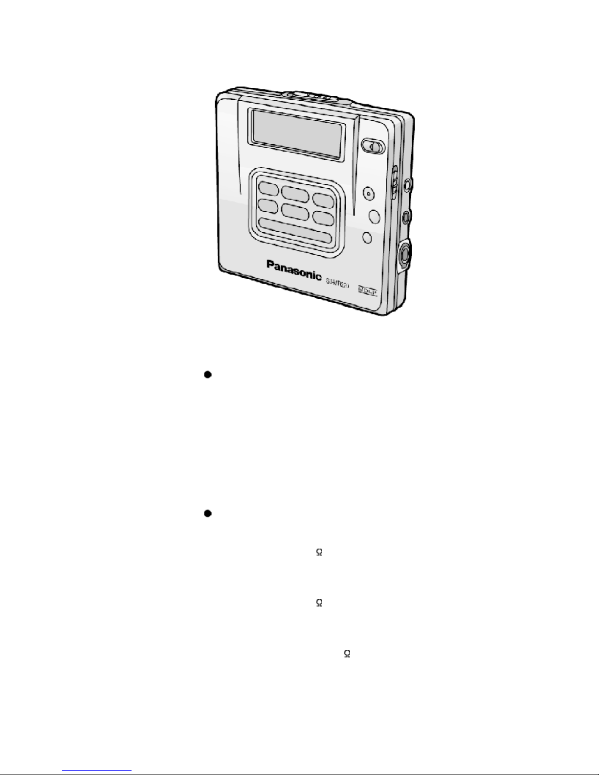
Dimensions (WxHxD)
Cabinet dimensions: 78.2x71.6x16.0
mm
incl.projecting parts: 80.4x74.1x18.3
mm
Weight: 115 g (with
battery)
88 g (without battery)
Playtime
(When used in hold mode, at 25°C, on a flat, stable surface)
Batterytype:PlaytimeRecord time
Rechargeable
Normal: About 11.5 hoursAbout 5.5 hours
LP2: About 15 hoursAbout 8 hours
LP4: About 17 hoursAbout 9.5 hours
Panasonic alkaline
Normal: About 42 hoursAbout 19 hours
LP2: About 54 hoursAbout 26 hours
LP4: About 62 hoursAbout 34 hours
Both together
Normal About 54 hoursAbout 25 hours
LP2: About 71 hoursAbout 34 hours
LP4: About 82 hoursAbout 44 hours
Notes:
- The playtime maybe less depending on the operating
conditions.
- Specifications are subject to charge without notice. Weight
and dimensions are approximate.
2001 Matsushita Electric Industrial Co., Ltd. All rights reserved.
Unauthorized copying and distribution is a violation of law.
3

1. Accessories
- Rechargeable battery................................ .............1pc.
(RP-BP62EYD)
- External batterycase...............................................1pc.
(RFA1537-S2)
- Carrying case.........................................................1pc.
(RFC0069-H)
- Stereo earphones..................................................1pc.
(L0BAB0000162)
- Connection cable..................................................1pc.
(K2KA39B00001)
For EB area
- AC adaptor.............................................................1pc.
(RFEA003B-S)
For EG, GCS areas
- AC adaptor.............................................................1pc.
(N0JCAD000001)
For GH area
- AC adaptor.............................................................1pc.
(RFEA004H-S)
- Wired remote control.............................................1pc.
(N2QCBD000012)
For EB, EG, GCS areas
- Wired remote control............................................1pc.
(N2QCBD000013)
2. Precation of Laser Diode
4

3. Operating Instructions
4. Handling Precautions for Traverse Deck
The laser diode in the traverse deck (optical pickup) maybreak down due to potential difference
caused bystatic electricityof clothes or human body.
So, be careful of electrostatic breakdown during repair of the traverse deck (optical pickup).
5

4.1. Handling the traverse deck (optical pickup)
1. The traverse deck (optical pickup) is an extremelyhigh-precision
construction and must not be subjected to impact, excessive
vibration, or other types of rough handling.
2. In order to prevent static electricitydamage to the laser diode, use a
short pin or similar tool to short the optical pickup’s flexible circuit
boards after theyhave been disconnected from the main circuit
board. (as shown in Fig. 1)
3. Handle the flexible circuit boards with care; excessive force could
cause them to be broken.
4. Do not turn the pre-set variable resistor (for adjustment of the laser
power); it has been adjusted at the factory.
(as shown in Fig. 2)
Fig. 1
Fig. 2
4.2. Grounding for electrostatic breakdown prevention
6

1. Human bodygrounding
Use the anti-static wrist strap to discharge the static electricityfrom
your body. (as shown in Fig. 3)
2. Work table grounding
Put a conductive material (sheet) or steel sheet on the area where
the traverse deck (optical pickup) is placed, and ground the sheet.
(as shown in Fig. 4)
Caution
The static electricityof your clothes will not be grounded through the
wrist strap.
So, take care not to let your clothes touch the traverse deck (optical
pickup).
Fig. 3
Fig. 4
5. Operation Checks and Component Replacement
Procedures
- This section describes procedures for checking the operation of the
major printed circuit boards and replacing the main components.
7

- For reassemblyafter operation checks or replacement, reverse the
respective procedures. Special reassemblyprocedures are
described onlywhen required.
- After replacing the main components (optical pickup or traverse
motor, etc.) of mechanism unit block, change to the adjust mode,
and then perform the “ROM/RAM auto-adjustment”.
5.1. Checking for the main P.C.B.
- Check the main P.C.B. (Aside) as shown below.
8

[Checking for the main P.C.B. (B side)]
- Each parts on main P.C.B. (B side) can not be checkesd directly,
however, for the checking of main component parts on P.C.B., refer
to the “Checking procedures of main components parts on the main
P.C.B. (B side).
5.2. Replacement for the intermediate cabinet
- Followthe (Step 1) - (Step 3) of item 5.1.
9

5.3. Replacement for the open knob and lock unit
- Followthe (Step 1) - (Step 3) of item 5.1.
- Followthe (Step 1) - (Step 3) of item 5.2.
5.4. Replacement for the traverse motor
- Followthe (Step 1) - (Step 3) of item 5.1.
10

11

5.5. Replacement for the LCD
- Followthe (Step 1) - (Step 3) of item 5.1.
- Followthe (Step 1) - (Step 3) of item 5.2.
12

13

5.6. Replacement for the lift motor
- Followthe (Step 1) - (Step 3) of item 5.1.
- Followthe (Step 1) - (Step 3) of item 5.2.
- Followthe (Step 1) of item 5.5.
14

5.7. Replacement for the optical pickup
- Followthe (Step 1) - (Step 3) of item 5.1.
- Followthe (Step 1) - (Step 3) of item 5.2.
- Followthe (Step 1) - (Step 4) of item 5.4.
- Followthe (Step 1) of item 5.5.
15

16

5.8. Replacement for the spindle motor
- Followthe (Step 1) - (Step 3) of item 5.1.
- Followthe (Step 1) - (Step 4) of item 5.4.
6. Measurements and Adjsutments
Note:
After replacing the main components (optical pickup or traverse motor, etc.) of mechanism unit
block, change to the adjust mode, and then perform the “laser power adjustment”, “off-set auto-
adjustment” and “playback-onlydisc/magneto-optical disc auto-adjustment”.
6.1. Instruments to prepare
1. Playback-onlydisc (Test disc RFKV0006)
17

2. Commerciallyavailable recordable disc (fullyrecorded with music)
(magneto-optical disc)
3. Laser power meter (LE8010 or compatible meter)
4. Remote controller
Note:
For use of MD cartridge type laser power meter, remove the intermediate cabinet before perform
the laser power adjustment (as for the method of disassembly, refer to “5. Operation checks and
main component replacement procedures”.).
6.2. Laser power adjustment, Playback-onlydisc/magneto-optical disc
auto- adjustment
6.2.1. Enter the adjustment mode
1. Set the batteryand connect the remote controller.
2. Turn off the power, and switch main unit’s HOLD switch off.
3. Press the buttons of the remote controller in order from 1 to 4 [ for
(EB, EG, GCS) areas, refer to Fig. 5. For (GH) area , refer to Fig. 6.]
Fig. 5
Fig. 6
18

4. When the adjustment mode is activated, “T0E1” or “T0E2” will be
displayed on the LCD of remote controller and unit [(EB, EG, GCS)
areas are displayed onlyunit]. After “T0E1” or “T0E2” is displayed,
select the desired adjustment item with the button or button
of the remote controller. (If it is not displayed, perform the
procedures written above again.)
Adjustment mode
Adjustment mode Display
Laser power adjustment T0**
Off-set automatic adjustment T1**
Magneto-optical disc automatic adjustment T2**
Playback-onlydisc automatic adjustment T3**
Automatic adjustment value check T4**
EFMjitter meajurement T5**
REC jitter meajurement T6**
Area setting T7**
Open T8**
Error rate measurement (double velocity) T9**
Open TA**
ROMcollection check sum TB**
DRAMcheck TC**
Reliabilitytest TD**
Tilt measurement (disc middle speed) TE**
PWB inspection (audio test) TF**
*In the displayof T0** ~ TF** shown above, you must adjust T0**, T1**, T2** and T3**. You must
perform the adjustment byobserving the order T0** T1** T2** T3**.
19

6.2.2. Laser Power Adjustment
Adjust each laser power: read power for reading (play) and write power for writing (record).
6.2.2.1. Set the Unit to the Adjustment Mode
Cautions
About handling the optical pickup and the magnetic head.
- The optical pickup and the magnetic head are structured precisely;
therefore, theyare veryfragile. Be careful not to touch them with the
edge of the laser power meter. Do not touch the lens.
- The sensor of the laser power meter is a veryfine part. Be careful not
to touch it to the optical pickup lens.
- Do not loosen or remove the magnetic head installing screw.
- The focus point of the laser reaches to 356°F. Therefore, avoid
adjusting using laser power for a long time because the sensor of
the laser power meter maybe burned.
- Do not allowthe write power to even momentarilyreach or exceed
6mW. Doing so will result in damage to the optical pickup.
- Do not set the unit to the laser power adjustment mode with the MD
loaded. Doing so mayresult in damage to the MD.
- Laser diode in the optical pickup maybe destroyed bythe
staticelectricitygenerated in your clothes or body. Be especially
careful with the static electricity.
6.2.2.2. Adjustment Procedure
1. Have “T0**” indicated on display, and move the optical pickup to the
most inside (onlywhen a MD cartridge type laser power meter is
used).
2. Set the laser power meter.
[For use of stick type laser power meter.]
2-1 Uncover the laser power meter (refer to Fig. 7).
2-2 Locate the sensor of the laser power meter right over above the
optical pickup (horizontallyat a level of the disc position). (as
shown in Fig. 8)
[For use of MD cartridge type laser power meter.]
2-1 Set the laser power meter and close the disc cover, fix it with
tape as not to open. (refer to Fig. 9).
20
Other manuals for SJ-MR220
3
Table of contents
Other Panasonic Mini Disc Recorder manuals

Panasonic
Panasonic SJ-MR100 User manual

Panasonic
Panasonic SJ-MR220 User manual

Panasonic
Panasonic SJ-MR100 User manual

Panasonic
Panasonic SJ-MR230DGH User manual

Panasonic
Panasonic SJ-MR200 User manual

Panasonic
Panasonic TH-55AS670M Assembly instructions

Panasonic
Panasonic SJ-MR200 User manual

Panasonic
Panasonic SJ-MR250 User manual

Panasonic
Panasonic SJ-MR100 User manual