Contents
Introduction............................................................................................................................................................................................................... 3
Model Overview....................................................................................................................................................................................................... 4
Model Delineation.............................................................................................................................................................................................. 4
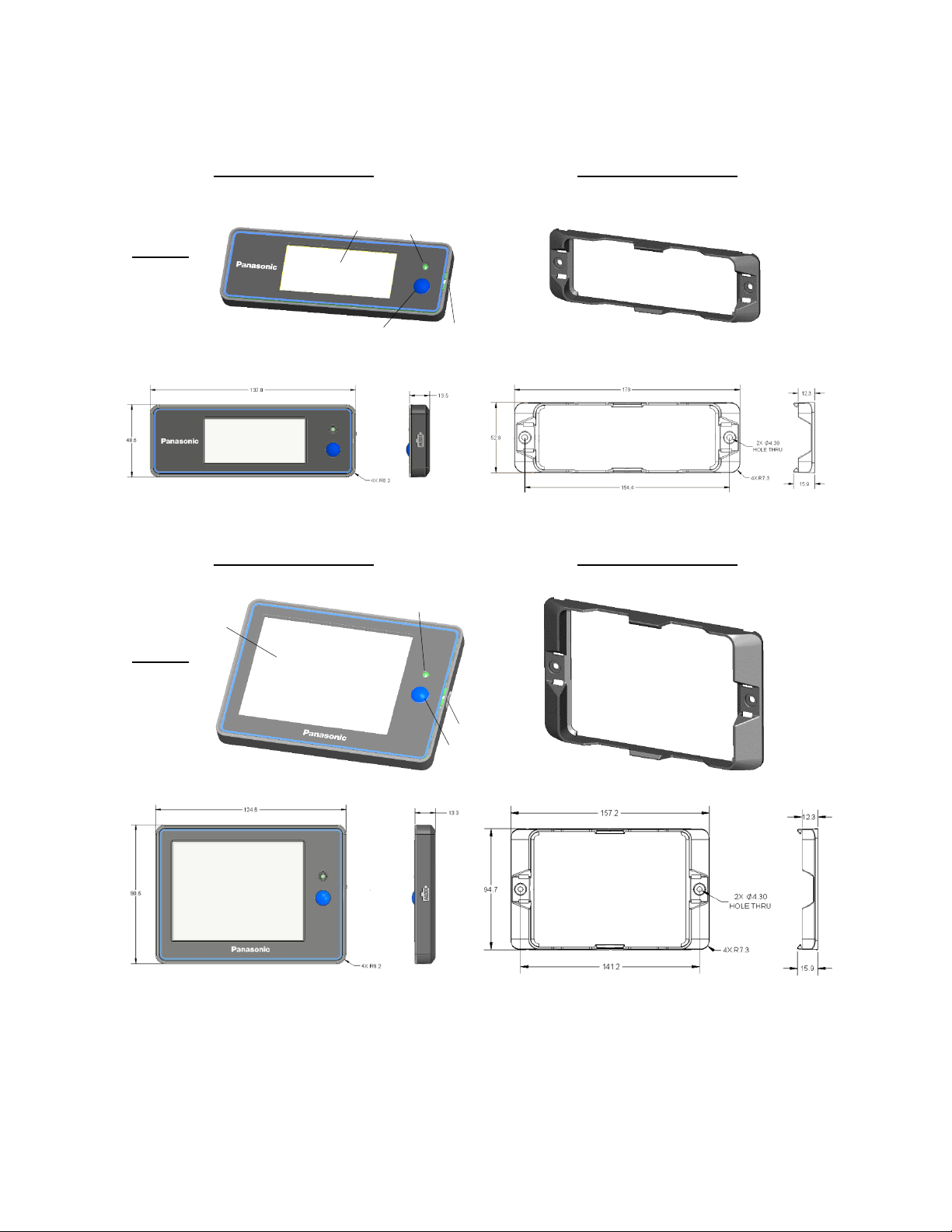
VIEW 3................................................................................................................................................................................................................ 4
VIEW 3 Bracket............................................................................................................................................................................................... 4
VIEW 4................................................................................................................................................................................................................ 4
VIEW 4 Bracket............................................................................................................................................................................................... 4
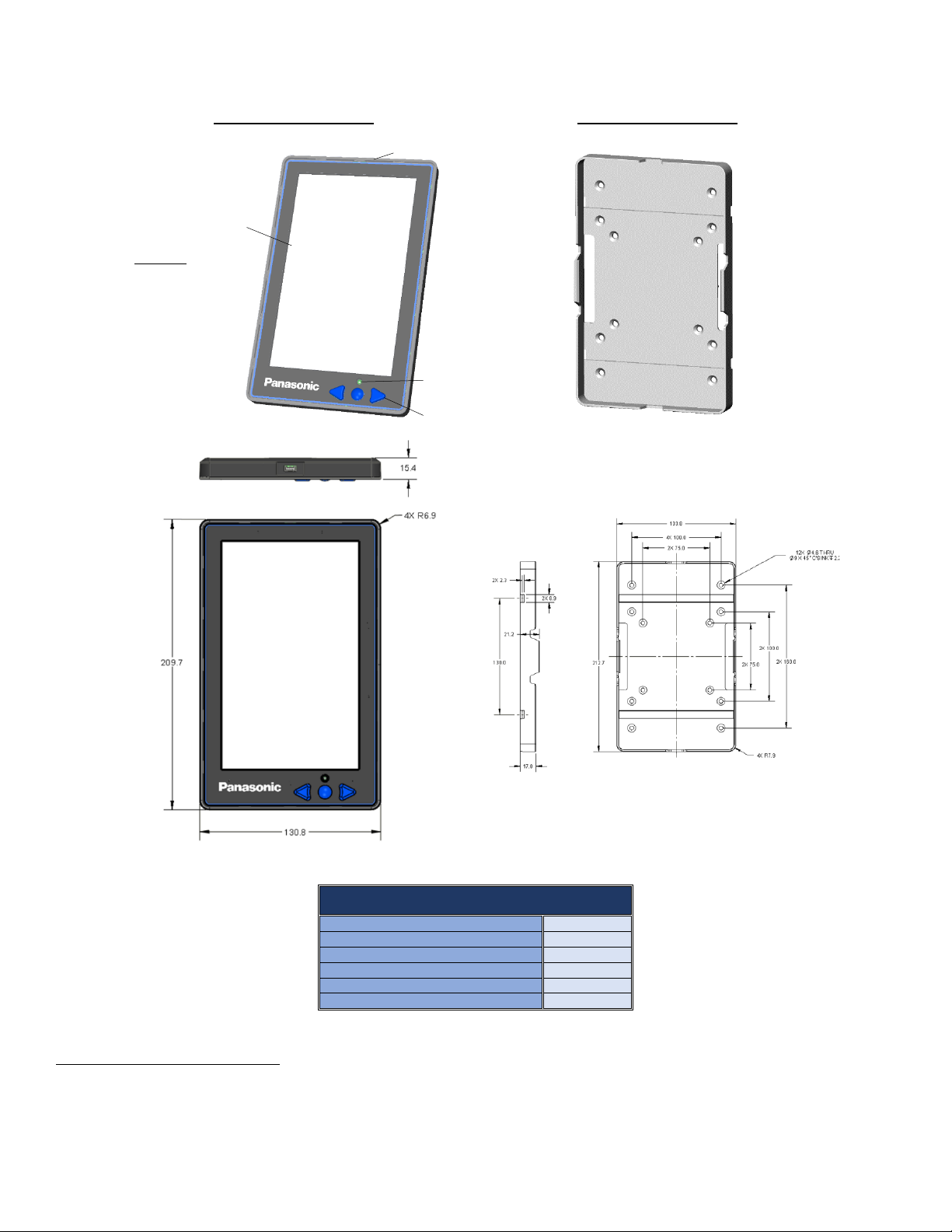
VIEW 7................................................................................................................................................................................................................ 5
VIEW 7 Bracket............................................................................................................................................................................................... 5
View Tag Specifications ................................................................................................................................................................................... 6
Physical.............................................................................................................................................................................................................. 6
Communication .............................................................................................................................................................................................. 6
Environment & Testing............................................................................................................................................................................... 7
Bracket.................................................................................................................................................................................................................... 7
Using Panasonic View Tags ................................................................................................................................................................................. 8
Installation & Integration................................................................................................................................................................................ 8
Connecting to Your System........................................................................................................................................................................ 8
User/View Tag Interaction ............................................................................................................................................................................. 8
Screen................................................................................................................................................................................................................. 8
LED....................................................................................................................................................................................................................... 8
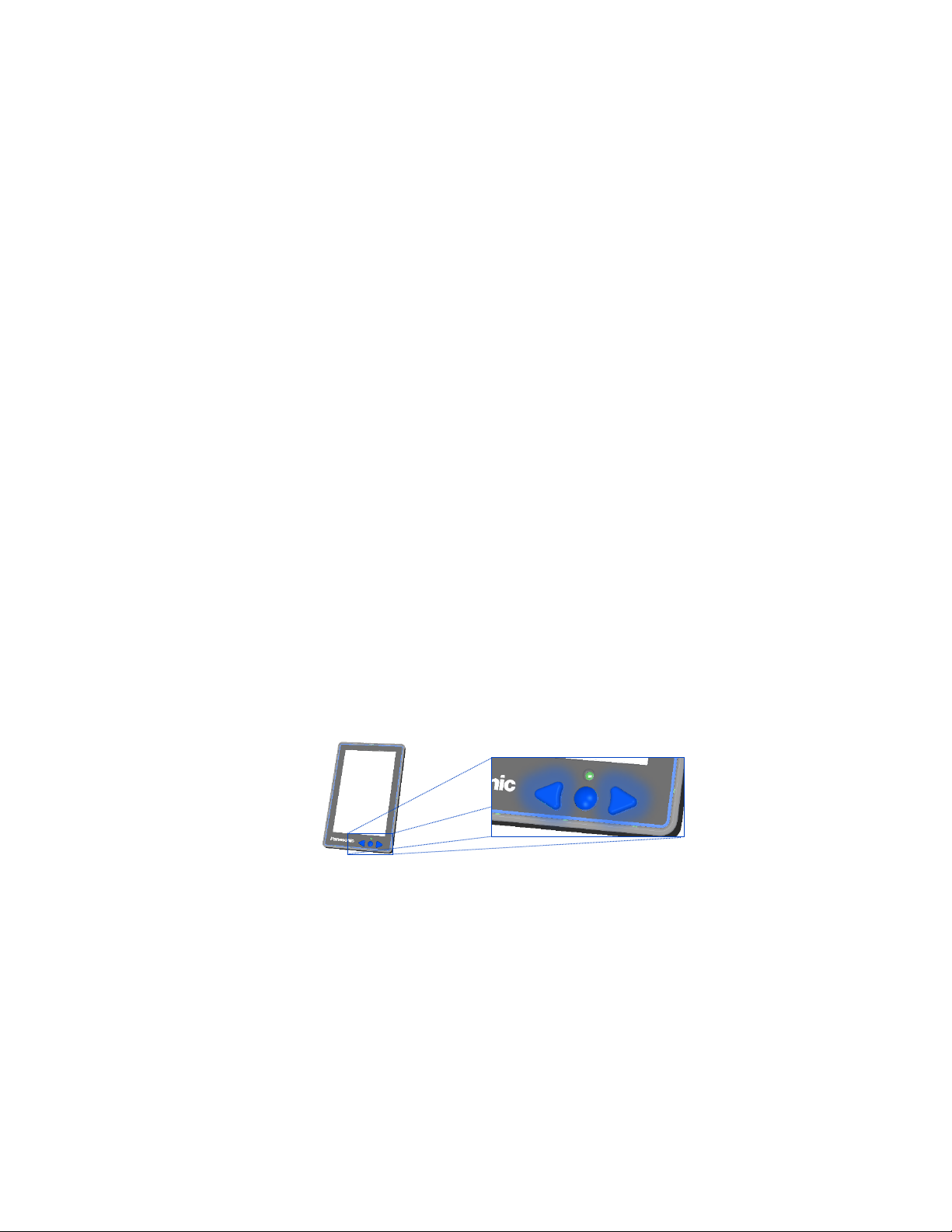
Button(s)........................................................................................................................................................................................................... 8
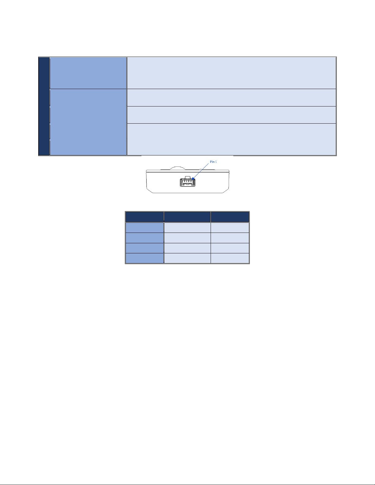
GPIO Port........................................................................................................................................................................................................... 9
System/View Tag Interaction........................................................................................................................................................................ 9
Bracket Mounting.............................................................................................................................................................................................10
Mounting Position.......................................................................................................................................................................................10
Mounting Options........................................................................................................................................................................................10
Contact Us.................................................................................................................................................................................................................11
Economic operators’ information in EU ......................................................................................................................................................11
Safety& Legal Information.................................................................................................................................................................................12
Health and Safety Warnings.........................................................................................................................................................................12
Safety Considerations.....................................................................................................................................................................................12
Acceptance Inspection....................................................................................................................................................................................12
Product Disclaimer ..........................................................................................................................................................................................12
General Disclaimer...........................................................................................................................................................................................13
Warranty Details...............................................................................................................................................................................................13
Guide Terms & Conditions............................................................................................................................................................................13