10
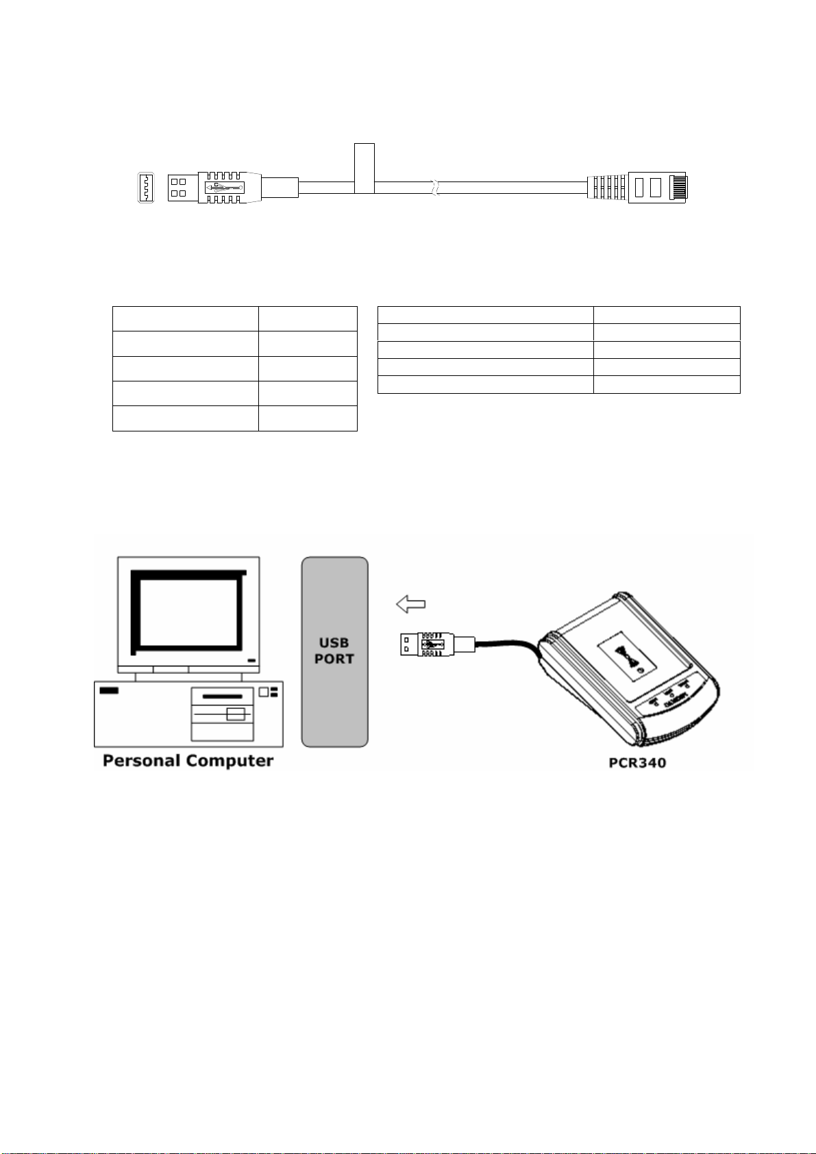
Installing USB Driver ( or PCR340-VC)
I you have PCR340-VC and you are ready to use its USB cable (WAS-T0043), you
need to install USB driver be ore connecting it with your computer. The USB driver
ile (SetupSel.exe) is in the bundled disk. You can double-click "SetupSel.exe" to
install USB driver. (I you have PCR340-00 and you are ready to use its USB cable,
you don’t need to install USB driver.)
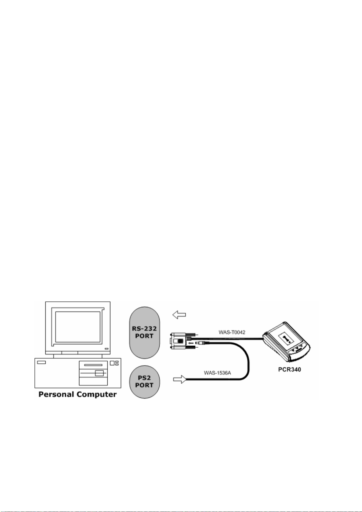
Con iguring PCR340 with the Con iguration So tware
The con iguration so tware (PCR340Setup_version_PSW00058.exe) is in the
bundled disk. Install the so tware irst. Connect PCR340 with your computer
through RS232 port and then run the so tware.
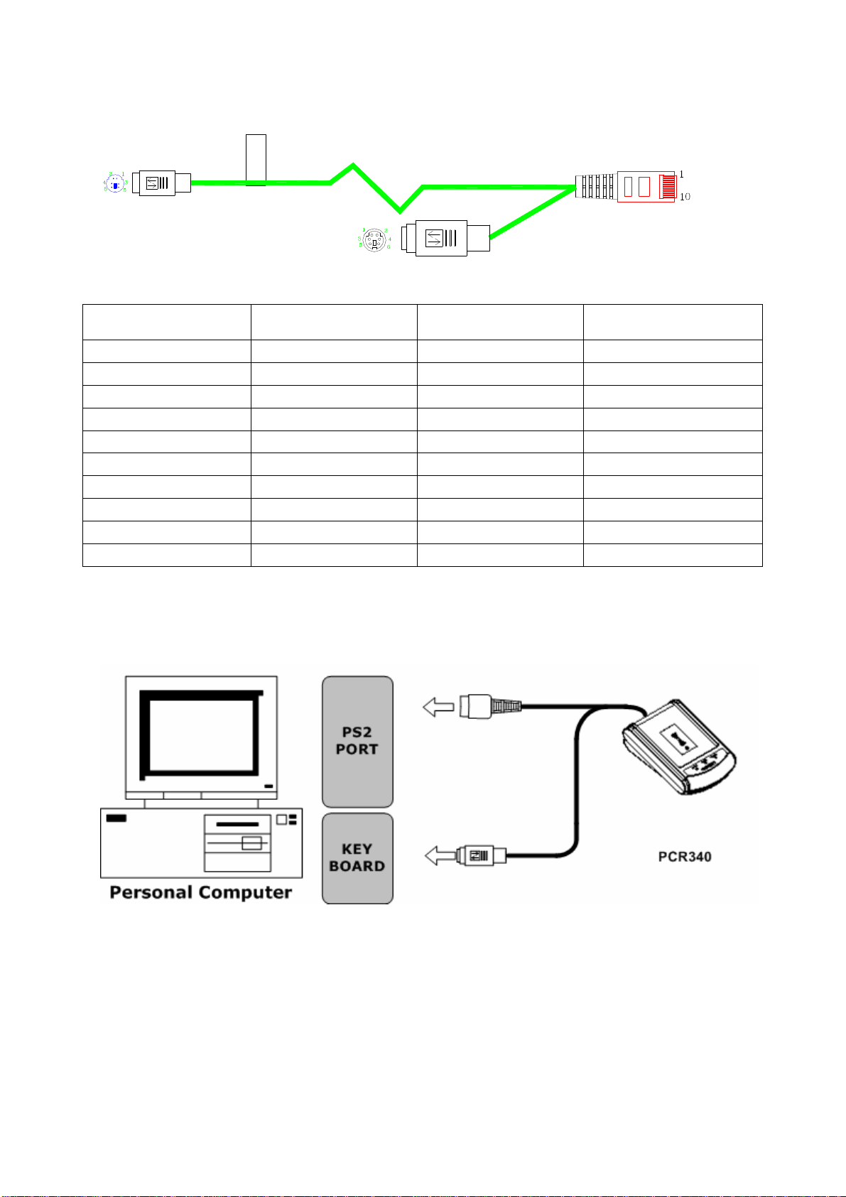
Note: (1) To connect PCR340-00 with our so tware, it allows you to use RS232 cable
only. I you use USB cable or PS/2 cable, the so tware will not be able to detect
PCR340-00. (2) To connect PCR340-VC with our so tware, it allows you to use RS232
cable or USB cable. I you use PS/2 cable, the so tware will not be able to detect
PCR340-VC.