1. .
OPERATION OF THE READER.
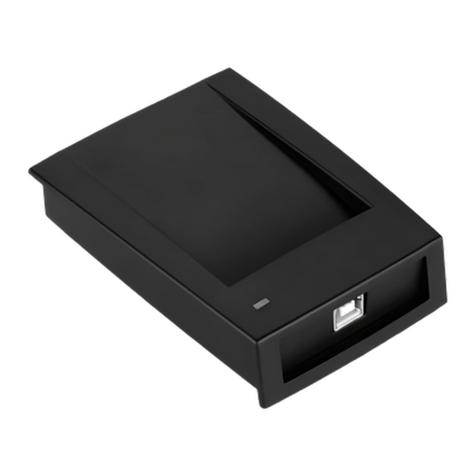
"Z-397" converter
GENERAL INFORMATION
"MATRIX-V"
2. FEATURES OF THE READER.
4.
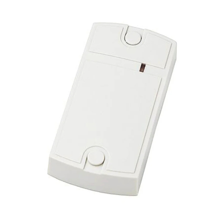
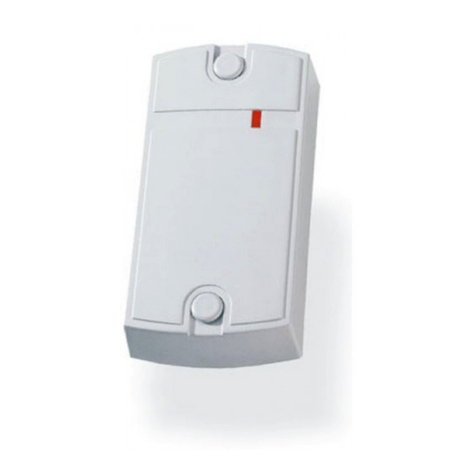
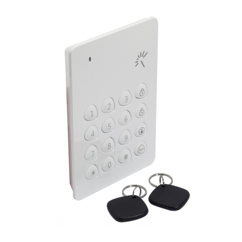
The reader is intended for application in the monitoring systems of management of access and allows to read out
numbers of identifiers (cards, charm, etc.) working in the EM-Marine standard and in the Keeloq standard at a frequency of 433
MHz, and also to transfer a code of the only a few identifier to the controler under protocols Dallas Touch Memory (iButton),
Wiegand 26 or on the RS-485 interface
- The increased range of reading of a code of cards of the EM-Marine standard (to 50 cm);
- Reading of radio charm codes (on the basis of HCS-300 chip), working in the Keeloq standard at a frequency of 433 Mhz;
- The case of a product possesses moisture-proof characteristics;
- Existence of an exit of RS-485 allows to connect the reader to the computer at a great distance (to 1200 m) via the Z-397
converter;
- At each reader the serial number which is necessary at the product “FirmWare”updating by the user.
The reader is mounted on a flat surface in closed from direct sunshine
and a precipitation place providing a free present of PROXIMITY card to it.
.
3. .INSTALLATION AND CONNECTION
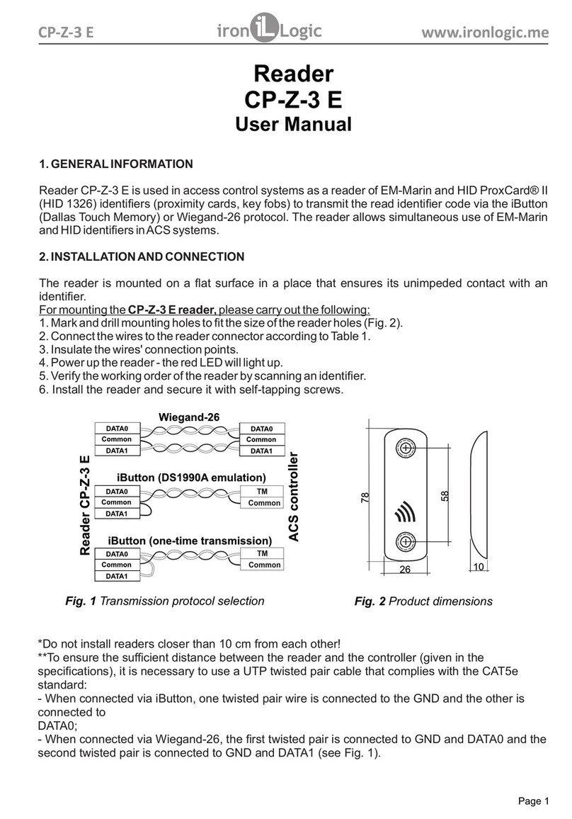
* not to install readers at distance 50 cm are closer!
** For ensuring remoteness of installation of the reader (specified in characteristics) it is necessary to use an UTP cable
with twisted couple (for example conforming to the CAT5e standard):
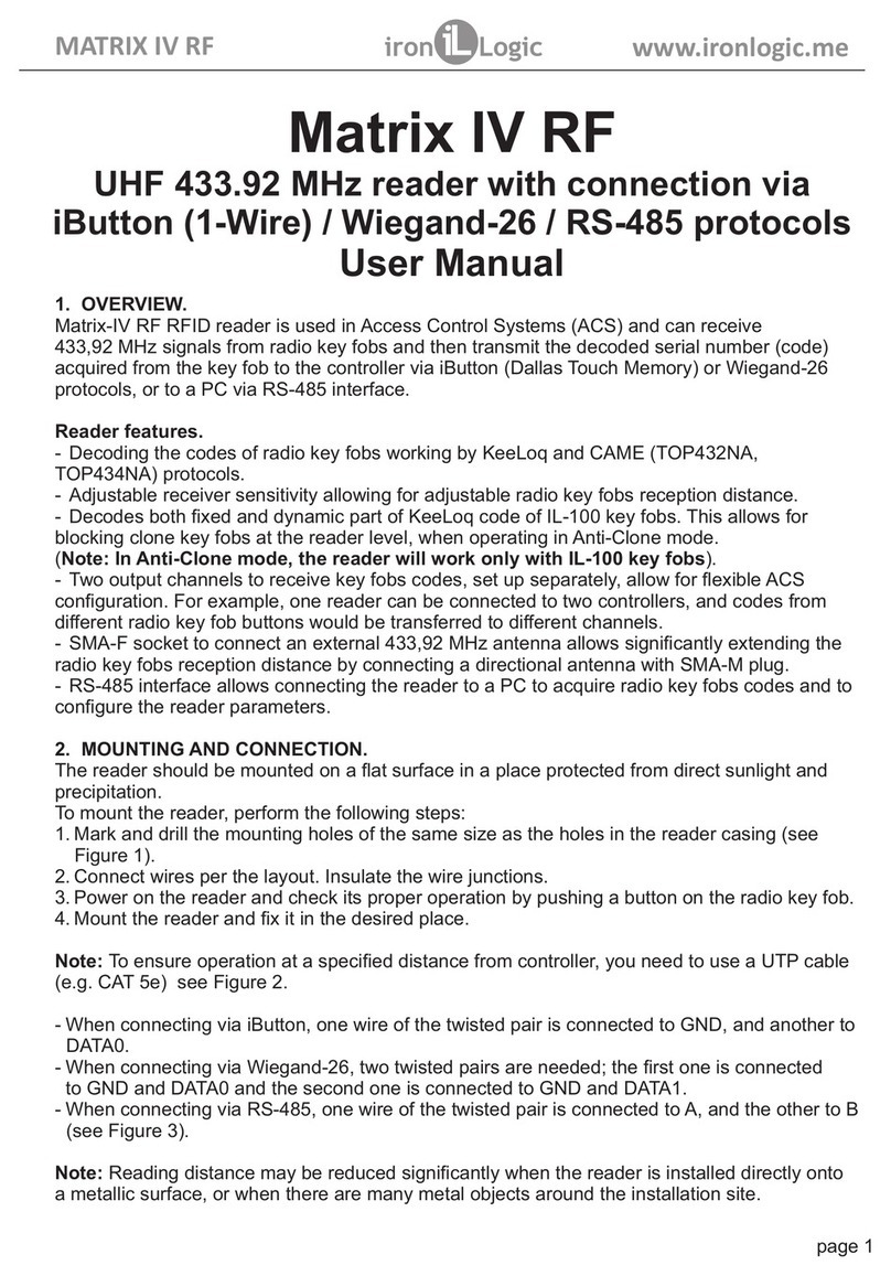
At connection on iButton one wire of twisted couple is connected on GND, the second on DATA0.
At connection on Weigand 26 the first twisted couple is connected between GND and DATA0, and the second twisted couple
is connected between GND and DATA1. (Fig. 3)
At connection on RS-485 one wire of twisted couple is connected on A, the second on B. (Fig. 4)
*** T at installation . For increase in range lay under the
reader a plate from dielectric (for example plywood) thickness not less than two centimeters.
When giving power on the reader during 3-5 seconds there is a setup of the reader (shine the red and green light-emitting
diodes). After control the reader is ready to work (the red light-emitting diode shines).
The reader has internal and external management of indication and a sound.
At internal management:
- there is no card in the field: the red shines;
- there was a card in the field: flash green and short sound signal;
- card in the field: there is no indication.
External management of indication and sound of the reader joins at detection of an operating signal from the controler on any
of management entrances. External control is exercised short circuit of an operating wire on the general wire. Always,
irrespective of existence of signals of external management, when reading number of the identifier will work a green light-
emitting diode and a sound (for the period of 100 milliseconds).
The got number of the identifier is transferred to DATA1 and DATA0 exits under the iButton or Wiegand-26 protocols depending
on a choice of the protocol of transfer (fig. 4), and also on A entrance and B entrance on the RS-485 interface (fig. 5).
At connection of the reader to the personal computer on RS 485 via the USB-485 in a window of the Hyper
Terminal program the name of the standard of the card and number in the Wiegand26 format is output. In a window of the
Hyper Terminal program for serial ports it is necessary to adjust the following parameters of communication: speed-9600, bit-
8, parity-no, stop bit-1, management of a stream - no. For a conclusion to the screen of the program of data on a product (serial
number) press the key "I" on the personal computer keyboard.
he range of reading of identifiers can sharply fall to a metal surface
Cable No. 1 (7 wires)
- for power connection
- exits of Dallas TM, Wiegand26
- external management of light-emitting
diodes and sound.
Color of a wire Purpose of a wire
Red +12V
Black GND
Brown DATA1
White DATA0
Green external management of a green light-emitting diode
Yellow external management of a red light-emitting diode
Blue external management of a sound
Color of a wire Purpose of a wire
А
B
А
В
Black input wires are intended for connection
Blue input to the converter
Red output wires are intended for connection external
Yellow output loadings of 120 Ohms or following device
Cable No.2 Connection on RS 485.
Cable No.1 Connection to the controler.
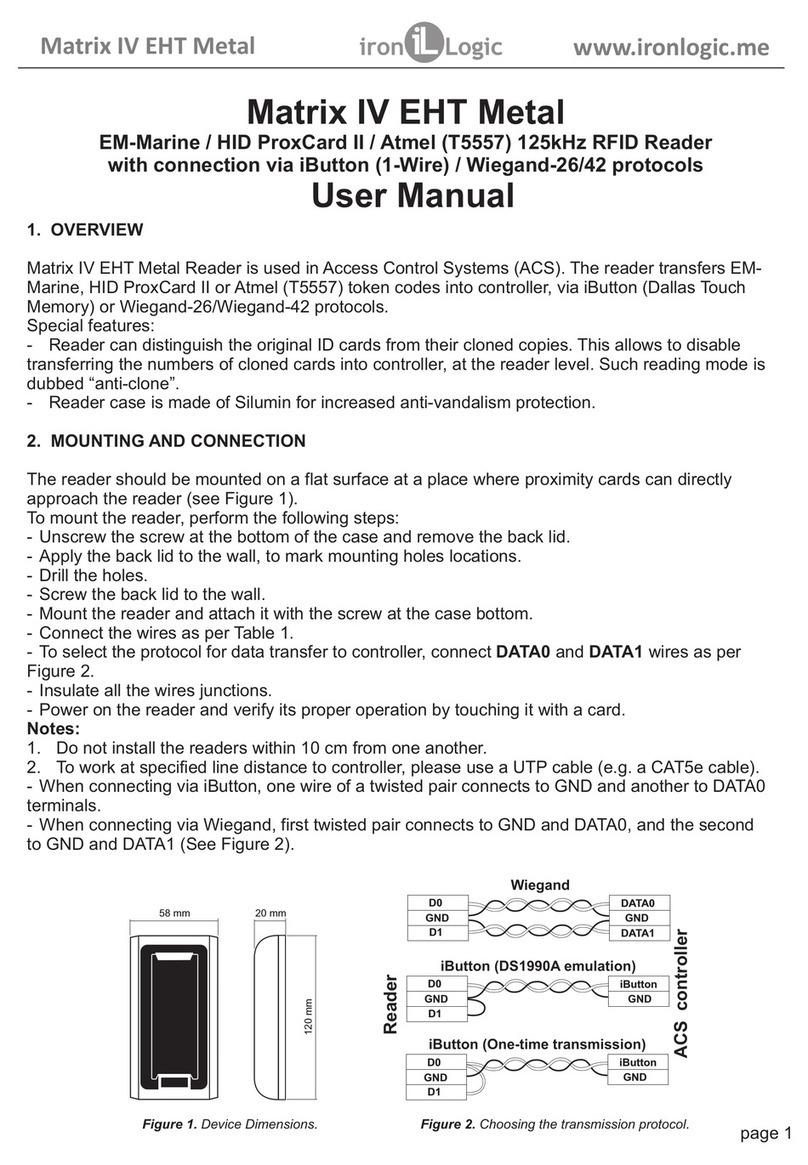
For installation of the reader execute the
following operations:
- Mark and drill openings for fastening under the size of
openings of the reader (fig. 1).
- Connect wires according to fig. 2, 3, 4, 5.
- In junctions of a wire insulate.
- Give and check operability of the reader a present of a
card or button pressing on a radio charm.
Attention! Before inclusion be convinced that in the field of
the reader there are no other cards with a working frequency
of 125 kHz.
- Install the reader on an installation site and fix it.
"MATRIX-V"
power
Fig.1 Overall dimensions.
170 мм
225 мм
36 мм
170 мм
225 мм
Cable No. 2 (4 wires)
- RS 485 exit.
Boutput
A output
Converter
USB - RS-485
Z-397
USB
120 Оm
A
Y
Fig.5 Connection cheme on RS-485.s
Fig.2 General view of the reader.
DATA1
GND
DATA0
GND
DATA0
DATA1
GND
TM
iButton (single transfer)
Wiegand
iButton (emulation DS1990A)
Controler
GND
Reader MATRIX-V
GND
DATA0
DATA1
GND
DATA0
DATA1
TM
Reader MATRIX-V
Crossing point
It is intended for shutdown reader
sound (to have a bite if necessary to
disconnect a sound).
Fig.3 Purpose of Wires.
Fig.4 Choice of the protocol of transfer.
Z
BB input
A input
Resistor

