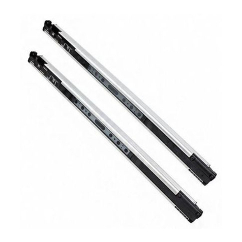
Panasonic SF4D Series User manual

2017.3 panasonic.net/id/pidsx/global
Safety Light Curtain Type 4
SF4D Series
Instruction Manual
WUME-SF4D-3

© Panasonic Industrial Devices SUNX Co., Ltd. 20172
(MEMO)

© Panasonic Industrial Devices SUNX Co., Ltd. 2017 3
Thank you very much for purchasing Panasonic Industrial Devices SUNX's Safety Light Curtain,
SF4D series.
Please read this Instruction Manual carefully and thoroughly for the correct and optimum use of
this product.
Kindly keep this manual in a convenient place for quick reference.
This device is an optoelectronic safety sensor that protects persons from injury or accident
which can be caused by dangerous parts of a machine.
This manual is for the following persons who have received appropriate training and have
knowledge of optoelectronic safety sensor and safety.
●Those who are in charge of installation of this device.
●Those who incorporate this device into systems or design them.
●Those who install and/or connect this device
●Those who manage or perform operations at sites where this device is used.
Notes
1) No part of this description should be copied or reprinted in any form or by any means without
prior permission in writing from the publisher.
2) The contents of this description are subject to change without notice for future improvement.
3)Everyeffortismadetoproducethisdescription.Ifyoundanyquestion,error,incorrectcol-
latingand/ormissingpage,pleasedonothesitatetocontactournearestlocalofcetoyou:
Panasonic Industrial Devices SUNX.
4) The original version of this description is written in Japanese and English.

© Panasonic Industrial Devices SUNX Co., Ltd. 20174
Contents
Chapter 1 Introduction ······································································ 7
1-1 Safety Cautions ···········································································8
1-2 Applicable Standards / Regulations················································ 11
1-3ConrmationofPackedObjects ···················································· 12
Chapter 2 Before Using The Device····················································13
2-1 Features··················································································· 14
2-2 Parts of the Device ····································································· 14
2-3 Protection Area·········································································· 18
2-3-1 Sensing Area·········································································18
2-3-2 Safety Distance······································································19
2-3-3EffectsofReectiveSurfaces····················································24
2-3-4 Preventing Mutual Interference··················································25
2-3-4-1 Interference Prevention Function ································25
2-3-4-2 Series Connection ···················································25
2-3-4-3 Parallel Connection (only line synchronization) ··············25
2-3-4-4 Preventing Mutual Interference by Device Placement······26
2-4 Mounting ·················································································· 28
2-4-1 Installing the Mounting Brackets ················································28
2-4-1-1
Using Beam Adjustment Mounting Bracket MS-SFD-1-□(Option)
·29
2-4-1-2
Using Intermediate Supporting Bracket MS-SFB-2(Option)
·31
2-4-1-3
Using No Dead-Space Beam Adjustment Mounting Bracket
MS-SFD-3-6(Option)
·················································33
2-4-1-4 Using SF4B-G Compatible Mounting Bracket
MS-SFD-4BG(Option) ·············································36
2-4-2InstallingtheBottomCapCables(Option) ···································38
2-4-3 Adding and Removing Sensors (Series Connection) ······················40
2-4-4 Mounting and Removing the Front Protective Cover ······················43
2-5 Wiring······················································································ 45
2-5-1 Power Supply Unit ··································································45
2-5-2Input/OutputCircuitDiagramsandOutputWaveforms··················46
2-5-3 Cable Wiring / Connections / Extension and Connector Pinouts ·······55
2-5-4 Basic Wiring ··········································································57
2-5-5 Wiring for Manual Reset (Interlock is Valid) ··································60
2-5-6 Wiring for Series Connection ····················································62
2-5-7WiringCongurationforValidExternalDeviceMonitorFunction·······64
2-5-8WiringCongurationforValidMutingFunction······························66
2-5-9
WiringforFunctionChangesUsingOptionalCommunicationModule
SF4D-TM1
············································································68
2-5-9-1 Wiring for Parallel Connection ····································68
2-5-9-2 Wiring for Mixed Series and Parallel Connection ············72
2-6 Adjustment················································································ 76
2-6-1 Beam Adjustment ···································································76
2-6-2OperationTest ·······································································80
2-6-3IndicatorOperation ·································································81

© Panasonic Industrial Devices SUNX Co., Ltd. 2017 5
Chapter 3 Functions ········································································99
3-1 Self-Diagnosis Function····························································· 100
3-2 Interlock Function····································································· 100
3-3 Lockout Release Function·························································· 102
3-4 Test Input Function ··································································· 103
3-5AuxiliaryOutput(Non-SafetyOutput)············································ 104
3-6 External Device Monitor Function ················································ 105
3-7 Muting Function ······································································· 107
3-8OverrideFunction ·····································································111
3-9 DIP Switch Settings ·································································· 113
3-10 Application indicator function····················································· 115
3-11
FunctionsThatCanbeSetUsingtheOptionalCommunicationModule
SF4D-TM1
············································································· 118
3-11-1 Fixed Blanking Function ······················································· 118
3-11-2 Floating Blanking Function ···················································· 119
3-11-3 Interlock Function································································ 120
3-11-4 External Device Monitor Function ··········································· 120
3-11-5AuxiliaryOutput ·································································· 121
3-11-6 Application Indicator Function ················································ 122
3-11-7 Muting Function ·································································· 123
3-11-8OverrideFunction ······························································· 125
3-11-9 Protection Function ····························································· 125
3-11-10I/OSettingFunction ··························································· 125
Chapter 4 Maintenance·································································· 127
4-1 Daily Inspection ······································································· 128
4-2 Periodic Inspection (Every Six Months)········································· 129
4-3 Inspection after Maintenance······················································ 129
Chapter 5 Troubleshooting······························································ 131
5-1 Emitter Troubleshooting····························································· 132
5-2 Receiver Troubleshooting ·························································· 135
Chapter6SpecicationsandDimensions ·········································· 141
6-1Specications·········································································· 142
6-2Options ·················································································· 148
6-3 Dimensions············································································· 154
6-3-1 Rear Mounting with MS-SFD-1-5 and MS-SFB-2 ························ 154
6-3-2 Side Mounting with MS-SFD-1-5 and MS-SFB-2························· 155
6-3-3 Rear Mounting with MS-SFD-1-6 and MS-SFB-2 ························ 156
6-3-4 Side Mounting with MS-SFD-1-6 and MS-SFB-2························· 157
6-3-5 Rear Mounting with MS-SFD-1-8 and MS-SFB-2 ························ 158
6-3-6 Side Mounting with MS-SFD-1-8 and MS-SFB-2························· 159
6-3-7 Mounting with MS-SFD-3-6 ···················································· 160
6-3-8 Rear Mounting with MS-SFD-4BG and MS-SFB-2 ······················ 161
6-3-9 Side Mounting with MS-SFD-4BG and MS-SFB-2 ······················· 162

© Panasonic Industrial Devices SUNX Co., Ltd. 20176
6-3-10 Mounting Brackets ······························································ 163
6-3-10-1 Beam Adjustment Mounting Bracket MS-SFD-1-5······· 163
6-3-10-2 Beam Adjustment Mounting Bracket MS-SFD-1-6······· 164
6-3-10-3 Beam Adjustment Mounting Bracket MS-SFD-1-8······· 165
6-3-10-4 Intermediate Support Bracket MS-SFB-2 ·················· 166
6-3-10-5 No Dead-Space Beam Adjustment Mounting Bracket
MS-SFD-3-6 ······················································· 167
6-3-10-6 SF4B-G Compatible Mounting Bracket MS-SFD-4BG · 168
Chapter7OtherInformation···························································· 169
7-1 Glossary················································································· 170
7-2 CE Marking Declaration of Conformity ·········································· 172

© Panasonic Industrial Devices SUNX Co., Ltd. 2017 7
Chapter 1 Introduction
1-1 Safety Cautions ··········································································8
1-2 Applicable Standards / Regulations················································ 11
1-3ConrmationofPackedObjects ···················································· 12

Introduction
© Panasonic Industrial Devices SUNX Co., Ltd. 20178
1-1 Safety Cautions Always observe
This section explains important rules that must be observed to prevent human injury and prop-
erty damage.
■ Thehazardsthatmayoccuriftheproductisusedincorrectlyaredescribedandclassiedby
level of harm.
WARNING Risk of death or serious injury.
CAUTION Risk of minor injury or property damage.
<Reference> It gives useful information for better use of this device.
■ Usethisdeviceasperitsspecications.Donotmodifythisdevicesinceitsfunctionsandca-
pabilities may not be maintained and it may malfunction.
■This device has been developed / produced for industrial use only.
■This device is suitable for indoor use only.
■Use of this device under the following conditions or environments is not presupposed. Please
consult us if there is no other choice but to use this device in such an environment.
1)Operatingthisdeviceunderconditionsorenvironmentsnotdescribedinthismanual.
2)Usingthisdeviceinthefollowingfields:nuclearpowercontrol,railroad,aircraft,auto
mobiles, combustion facilities, medical systems, aerospace development, etc.
■When this device is to be used for enforcing protection of a person from any danger occurring
around an operating machine, the user should satisfy the regulations established by national
orregionalsecuritycommittees(OccupationalSafetyandHealthAdministration:OSHA,the
European Standardization Committee, etc.). Contact the relative organization(s) for details.
■In case of installing this device to a particular machine, follow the safety regulations in regard
to appropriate usage, mounting (installation), operation and maintenance. The users includ-
ing the installation operator are responsible for the introduction of this device.
■Note that this device may be damaged if it is subject to a strong shock (if it is dropped onto
theoor,forexample).
■Use this device by installing suitable protection equipment as a countermeasure for failure,
damage, or malfunction of this device.
■Before using this device, check whether the device performs properly with the functions and
capabilitiesasperthedesignspecications.
■In case of disposal, dispose this device as an industrial waste.

Introduction
© Panasonic Industrial Devices SUNX Co., Ltd. 2017 9
WARNING
♦Machine designer, installer, employer and operator
●The machine designer, installer, employer and operator are solely responsible to ensure
that all applicable legal requirements relating to the installation and the use in any appli-
cationaresatisedandallinstructionsforinstallationandmaintenancecontainedinthe
instruction manual are followed.
●Whether this device functions as intended to and systems including this device comply
with safety regulations depends on the appropriateness of the application, installation,
maintenance and operation. The machine designer, installer, employer and operator are
solely responsible for these items.
♦Engineer
●The engineer would be a person who is appropriately educated, has widespread knowl-
edge and experience, and can solve various problems which may arise during work, such
as a machine designer, installer or employer etc.
♦Operator
●The operator should read this instruction manual thoroughly, understand its contents, and
perform operations following the procedures described in this manual for the correct op-
eration of this device.
●In case this device does not perform properly, the operator should report this to the person
in charge and stop the machine operation immediately. The machine must not be operated
untilcorrectperformanceofthisdevicehasbeenconrmed.
♦Environment
●Do not use a mobile phone or a radio phone near this device.
●Ifthereexistsareectivesurfaceintheplacewherethisdeviceistobeinstalled,make
suretoinstallthisdevicesothatreectedlightfromthereectivesurfacedoesnotenter
into the receiver, or take countermeasures such as painting, masking, roughening, or
changingthematerialofthereectivesurface,etc.Failuretodosomaycausethedevice
not to detect, resulting in death or serious injury.
● Donotinstallthisdeviceinthefollowingplaces:
1)Areasexposedtointenseinterference(extraneous)lightsuchashigh-frequencyuo-
rescentlamp(invertertype),rapidstarteruorescentlamp,stroboscopiclightsordirect
sunlight.
2) Areas with high humidity where condensation is likely to occur
3) Areas exposed to corrosive or explosive gases
4)Areasexposedtovibrationorshockoflevelshigherthanthatspecied
5) Areas exposed to contact with water
6) Areas exposed to too much steam or dust
♦Installation
●Always keep the correctly calculated safety distance between this device and the danger-
ous parts of the machine.
●Install extra protection structure around the machine so that the operator must pass
through the sensing area of this device to reach the dangerous parts of the machine.
●Install this device such that some part of the operator’s body always remains in the sens-
ing area when operator is done with the dangerous parts of the machine.
● Donotinstallthisdeviceatalocationwhereitcanbeaffectedbywallreection.
●When installing multiple sets of this device, connect the sets and, if necessary, install
some barriers such that mutual interference does not occur. For details, refer to “2-3-4
Preventing Mutual Interference”.
● Donotusethisdeviceinareectiveconguration.

Introduction
© Panasonic Industrial Devices SUNX Co., Ltd. 201710
WARNING
♦Machine in which this device is installed
●Whenthisdeviceisusedin“PSDImode”,anappropriatecontrolcircuitmustbecong-
ured between this device and the machine. For details, be sure to refer to the standards
and regulations applicable in each region or country.
●In Japan, do not use this device as a safety device for press machine.
●Do not install this device with a machine whose operation cannot be stopped immediately
in the middle of an operation cycle by an emergency stop equipment.
● Thisdevicestartstheperformanceafter2secondsfromthepowerON.Havethecontrol
system started to function with this timing.
♦Wiring
● BesuretocarryoutthewiringinthepowersupplyOFFcondition.
●All electrical wiring should conform to the regional electrical regulations and laws. The wir-
ing should be done by engineer(s) having the special electrical knowledge.
●Do not run the wires together with high-voltage lines or power lines or put them in the
same raceway. This can cause malfunction due to induction.
●In case of extending the cable of the emitter or the receiver, each can be extended up to
70m by using the exclusive cable. Taking cable voltage drop into account, the cable length
differsaccordingtothesourcecurrent/sinkcurrentofthecontroloutput(OSSD1/2).For
details, refer to “6-1 Specications”.Usingacablelengthoutsidethespecicationsmay
cause the device to malfunction, possibly resulting in death or serious injury.
●Do not apply stress such as excessive bending or pulling to a cable or the extracted part of
a cable. In particular, when the temperature is low, cable materials harden, and when the
temperature is high, the materials soften, and so take care that cables may break if they
are subject to stress such as bending or pulling when the temperature is low or high.
● Donotcontrolthedeviceonlyatonecontroloutput(OSSD1/2).
● InorderthattheoutputisnotturnedtoONduetoearthfaultofthecontroloutput(OSSD1
/ 2) wires, be sure to ground to 0V side (PNP output) / +V side (NPN output).
●When using this device in Korea with S-mark, be sure to ground to 0V side (PNP output).
♦Maintenance
●When replacement parts are required, always use only genuine supplied replacement
parts. If substitute parts from another manufacturer are used, the device may not come to
detect, result in death or serious injury.
●The periodical inspection of this device must be performed by an engineer having the spe-
cial knowledge.
●After maintenance or adjustment, and before starting operation, test this device following
theprocedurespeciedin“Chapter 4 Maintenance”.
●Clean this device with a clean cloth. Do not use any volatile chemicals.
♦Others
● Nevermodifythisdevice.Modicationmaycausethedevicenottodetectobjects,result-
ing in death or serious injury.
● Donotusethisdevicetodetectobjectsyingoverthedetectionarea.
●Do not use this device to detect transparent objects, translucent objects or objects smaller
thanthespeciedminimumobjecttobedetected.

Introduction
© Panasonic Industrial Devices SUNX Co., Ltd. 2017 11
1-2 Applicable Standards / Regulations
This device complies with the following standards and regulations.
<EU Directives>
EU Machinery Directive 2006/42/EC
EMC Directive 2014/30/EU
RoHSDirective2011/65/EU
<European Standards>
EN 61496-1/2 (Type 4), EN 55011, EN 61000-6-2, EN 50178
ENISO13849-1:2015(Category4,PLe)
<International Standards>
IEC61496-1/2(Type4),ISO13849-1:2015(Category4,PLe),IEC61508-1to7(SIL3)
<Japanese Industrial Standards (JIS)>
JIS B 9704-1/2 (Type 4), JIS B 9705-1 (Category 4), JIS C 0508-1 to 7 (SIL3)
<Standards in US / Canada>
ANSI/UL 61496-1/2 (Type 4)
CAN/CSA C22.2 No.14, CAN/CSA E61496-1/2
<Regulations in US>
OSHA1910.212,OSHA1910.217(C),ANSIB11.1toB11.19,ANSI/RIA15.06
ForMachineryDirective,typecerticationaNotiedBodyTÜVSÜDhasbeenacquired.
For the standards in US / Canada, CTÜVUSmarkbyaNotiedBodyTÜVSÜDhasbeenac-
quired.
<Standards in China>
GB 4584
<Standards in Korea>
S1-G-1-2009, S2-W-5-2009
TheS-markcerticationcertiedbyKoreaOccupationalSafety&HealthAgency(KOSHA)has
been acquired.
<Reference>
TheconformanceofthisdevicetoJIS,OSHAandANSIisbasedonourself-evaluation.
The CTÜVUS mark indicatesthatthisdeviceconformstotheNRTLcertication(suchasUL)in
theUSandCSAcerticationinCanada.
The mark shown on the product indicates that this device has acquired the S-mark.
WARNING
●Since this device has not received “Type Examination” in Article 44-2 of the Industrial Safety and
HealthAct,itcannotbeusedinJapanasthe“Safetydeviceforpressmachineandshearing
machine”speciedinArticle42ofthesaidlaw.
●Beforeusingthisdeviceinatargetregionotherthantheabove,besuretoconrmthestan-
dards / regulations applied in the relevant nation and region.

Introduction
© Panasonic Industrial Devices SUNX Co., Ltd. 201712
Whenusingthisdevice,congureacontrolsystemsatisfyingthefollowingrequirementstoestab-
lish a system-wide safety.
To use in Category 4 or 3
●To prevent the loss of the safety function due to a single fault.
Besuretousecontroloutput(OSSD1/2)oftwosystems.
●To prevent the loss of the safety function due to accumulation of faults.
Congureacontrolsystemthatcanmonitorthecontroloutput(OSSD1/2)andstopthede-
vice if discrepancy is detected.
<Example of inconsistence detection method>
(Example 1) Use of relay unit and controller for light curtain
(Example2) Monitoringofcontroloutputs(OSSD1/2)withthesafetyPLC.
(Example 3) Monitoring of contact welding when safety relay is used
To use in Category 2
Whenusingthecontroloutput(OSSD)ofonlyonesystem,connectauxiliaryoutputtoPLC,etc.,
tomonitortheoperationofthisdevice.Inthiscase,congureacontrolsystemthatstopsthede-
vicewhendiscrepancybetweencontroloutput(OSSD)andauxiliaryoutputisdetected.Inplace
oftheauxiliaryoutput,controloutput(OSSD)ofonemoresystemisavailable.
1-3 Conrmation of Packed Objects
□ Mainbody:emitterandreceiver Oneforeach
□Test Rod 1 piece
SF4D-F□:SF4B-TR14 (ø14 × 220mm), SF4D-H□:SF4B-TR25 (ø25 × 220mm)
□Quick Instruction Manual (Japanese, English, Chinese, Korean) 1 pc. for each language
□General Information for Safety, Compliance, and Instructions (23 languages) 1 pc.

© Panasonic Industrial Devices SUNX Co., Ltd. 2017 13
Chapter 2 Before Using The Device
2-1 Features··················································································· 14
2-2 Parts of the Device ····································································· 14
2-3 Protection Area·········································································· 18
2-3-1 Sensing Area·········································································18
2-3-2 Safety Distance······································································19
2-3-3EffectsofReectiveSurfaces····················································24
2-3-4 Preventing Mutual Interference··················································25
2-3-4-1 Interference Prevention Function ································25
2-3-4-2 Series Connection ···················································25
2-3-4-3 Parallel Connection (only line synchronization) ··············25
2-3-4-4 Preventing Mutual Interference by Device Placement······26
2-4 Mounting ·················································································· 28
2-4-1 Installing the Mounting Brackets ················································28
2-4-1-1
Using Beam Adjustment Mounting Bracket MS-SFD-1-□(Option)
·29
2-4-1-2
Using Intermediate Supporting Bracket MS-SFB-2(Option)
·31
2-4-1-3
Using No Dead-Space Beam Adjustment Mounting Bracket MS-SFD-3-6(Option)
·33
2-4-1-4
Using SF4B-G Compatible Mounting Bracket MS-SFD-4BG(Option)
·36
2-4-2InstallingtheBottomCapCables(Option) ···································38
2-4-3 Adding and Removing Sensors (Series Connection) ······················40
2-4-4 Mounting and Removing the Front Protective Cover ······················43
2-5 Wiring······················································································ 45
2-5-1 Power Supply Unit ··································································45
2-5-2Input/OutputCircuitDiagramsandOutputWaveforms··················46
2-5-3 Cable Wiring / Connections / Extension and Connector Pinouts ·······55
2-5-4 Basic Wiring ··········································································57
2-5-5 Wiring for Manual Reset (Interlock is Valid) ··································60
2-5-6 Wiring for Series Connection ····················································62
2-5-7WiringCongurationforValidExternalDeviceMonitorFunction·······64
2-5-8WiringCongurationforValidMutingFunction······························66
2-5-9
WiringforFunctionChangesUsingOptionalCommunicationModuleSF4D-TM1
·68
2-5-9-1 Wiring for Parallel Connection ····································68
2-5-9-2 Wiring for Mixed Series and Parallel Connection ············72
2-6 Adjustment················································································ 76
2-6-1 Beam Adjustment ···································································76
2-6-2OperationTest ·······································································80
2-6-3IndicatorOperation ·································································81

Before Using This Device
© Panasonic Industrial Devices SUNX Co., Ltd. 201714
2-1 Features
Thisdeviceisalightcurtainwiththefollowingfeatures:
●A special controller is not required.
● PNPorNPNcanbeselectedforthecontroloutput(OSSD1/2).
●Upper application indicator and lower application indicator make beam alignment easy.
●For details on options, refer to “6-2 Options”.
2-2 Parts of the Device
Emitter Beam axis
Gray cable
Receiver
Gray cable (with black line)
Indicator
Indicator
Indicator
Indicator
Indicator

Part Description
© Panasonic Industrial Devices SUNX Co., Ltd. 2017 15
<Emitter>
Emits light toward the facing receiver. The status of the emitter is indicated by the indicators.
<Receiver>
Receiveslightfromthefacingemitter.Thecontroloutput(OSSD1/2)turnsONwhenlightfrom
theemitterisreceivedonallbeamchannels,andturnsOFFwhenlightisblockedononeor
more beam channels. [Except when the muting function or blanking function (Note) is used.]
The status of the receiver is indicated by the indicators.
Note: BlankingfunctionsettingsareconguredusingthecommunicationmoduleSF4D-TM1 (option) and Con-
guratorLightCurtainsoftware.
Please purchase the SF4D-TM1communicationmoduleseparately.TheConguratorLightCurtainsoft-
ware can be downloaded free-of-charge from our website (panasonic.net/id/pidsx/global).
<Beam channels>
Light emitting elements are arranged in the emitter and light receiving elements are arranged in
the receiver at intervals of 10mm (SF4D-F□), 20mm (SF4D-H□), or 40mm (SF4D-A□).
<Indicators>
Emitter:
Light emission intensity control indicator
Receiver:
Function setting indicator
Digital indicator
Stable light
reception indicator
Frequency indicator
Upper application indicator
Lower application indicator
Upper application
indicator
Lower application
indicator
Emitter:Operationindicator
Receiver:OSSDindicator
Emitter:Testindicator
Receiver:Interlockindicator

Part Description
© Panasonic Industrial Devices SUNX Co., Ltd. 201716
●Emitter/receiver common
Name Function
Line synchronization Opticalsynchronization
Upper application indicator
(Blue/Red/Green/Orange)
(Note 1)
<When beam axis alignment mode is set>
Controloutput(OSSD1/2)ON:Lightsblue“ ”
Whentopendbeamchannelreceiveslight:Lightsred“ ”
Whentopendbeamchannelisblocked:TurnsOFF
<When application mode is set>
Whenapplicationindicatorinput1isON:Lightsgreen“ ”
Whenapplicationindicatorinput2isON:Lightsred“ ”
Whenapplicationindicatorinput1/2areON:Lightsorange“ ”
Whenapplicationindicatorinput1/2areOFF:TurnsOFF
Lower application indicator
(Blue/Red/Green/Orange)
(Note 1)
<When beam axis alignment mode is set>
Controloutput(OSSD1/2)ON:Lightsblue“ ”
Whenbottomendbeamchannelreceiveslight:Lightsred“ ”
Whenbottomendbeamchannelisblocked:TurnsOFF
<When application mode is set>
Whenapplicationindicatorinput1isON:Lightsgreen“ ”
Whenapplicationindicatorinput2isON:Lightsred“ ”
Whenapplicationindicatorinput1/2areON:Lightsorange“ ”
Whenapplicationindicatorinput1/2areOFF:TurnsOFF
Stable light reception indicator
(Green/Orange)
Whenlightreceptionisstable:Lightsgreen“ ”
Whenlightreceptionisunstable:Lightsorange“ ”
Whenlightisblocked:TurnsOFF
Digital indicator
(Green / Yellow)
Received
light intensity
(Green)
Lightintensity/Level3:Lightsgreen“ ”
Lightintensity/Level2:Lightsgreen“ ”
Lightintensity/Level1:Lightsgreen“ ”
Whenlightisblocked:TurnsOFF
Error (Yellow) Normaloperation:TurnsOFF,Error:Yellownumberblinksorlights“ ”
Polarity
(Yellow)
WhenPNPoutputisset:Lightsyellow“ ” (only during startup)
WhenNPNoutputisset:Lightsyellow“ ” (only during startup)
Frequencyindicator(Orange)
-
Whenfrequency1isset:Lightsorange“ ”
Whenfrequency2isset:Lightsorange“ ”
●Emitter
Name Function
Line synchronization Opticalsynchronization
Light emission intensity control
indicator(Orange)[CTRL] Shortmode:TurnsOFF,Longmode:Lightsorange“ ”
Testindicator(Orange)[TEST] Duringtest:Lightsorange“ ”,Normaloperation:TurnsOFF
Operationindicator
(Red/Green)[OP]
Controloutput(OSSD1/2)OFF:
Lights red “ ”
Controloutput(OSSD1/2)ON:
Lights green “ ”
Normaloperation:Lightsgreen“ ”
Error:Lightsred“ ”
●Receiver
Name Function
Line synchronization Opticalsynchronization
Function setting indicator
(Orange)[FUNC]
Communicationmoduleconnected:Blinksorange“ ”
Blankingfunctionorparallelconnectionused:Lightsorange“ ” (Note 2)
Interlock indicator (Yellow)
[LOCK] Interlockactivated:Lightsyellow“ ”,Allothertimes:TurnsOFF
OSSDindicator(Red/Green)
[OSSD]
Controloutput(OSSD1/2)OFF:Lightsred“ ”
Controloutput(OSSD1/2)ON:Lightsgreen“ ”
Notes:1) Inthecaseofopticalsynchronization,theupperapplicationindicatorandlowerapplicationindicatoron
theemitterremainOFF.
2) For details on the blanking function and parallel connection, refer to “3-11 Functions That Can be Set
Using the Optional Communication Module SF4D-TM1”.
3) Names in brackets [ ] are names that are indicated on the device.

Part Description
© Panasonic Industrial Devices SUNX Co., Ltd. 2017 17
●How to check product information
Product information is shown on the plate on the side of the product.
Model No. Version Emitter or receiver
Version
Ver. 1.11 Ver. 2.0
ConguratorLightCurtain
software
Checking basic information ○ ○
Monitoring operations ○ ○
Checking histories such as errors
-
○
Collating settings
-
○
Reading and writing settings
-
○
Communication module
SF4D-TM1 (option)
Copy function
-
○
Saved data initialization function
-
○
○:Available,-:Unavailable

Protection Area
© Panasonic Industrial Devices SUNX Co., Ltd. 201718
2-3 Protection Area
2-3-1 Sensing Area
WARNING
●Be sure to install a protection structure around the machine so that the operator must pass
through the sensing area of the device to reach dangerous parts of the machine.
Ensure that part or all of the operator’s body remains in the sensing area when the operator
works with dangerous parts of the machine. Risk of death or serious injury if the operator's body
is not detected.
● Donotuseinareectivetypeorrecursivereectivetypesetup.
●Multiple receivers (emitters) cannot be connected for use with a single emitter (receiver).
The sensing area is the zone formed by the sensing height of the device and the sensing range
between the emitter and the receiver.
The sensing height of the device is determined by the number of beam channels.
The sensing range of the SF4D-F□ is 0.2 to 7m (0.8 to 12m in long mode). The sensing range
of the SF4D-H□ and SF4D-A□ is 0.2 to 9m (0.8 to 15m in long mode).
If used at less than 0.2m (less than 0.8m in long mode), optical system effects may cause mal-
functioning.
Top
Bottom
Sensing height
(Protection height)
The sensing height (pro-
tection height) is the length
from the top to the bottom
of the device.
Emitter Receiver
Sensing area
Sensing range (effective)
Sensing height
(Protection height)
<Example of correct sensing area setup>
Dangerous
part
Sensing
area Dangerous
part
Protective
structure
Sensing area
<Example of incorrect sensing area setup>
Dangerous
part
Sensing
area
Sensing
area
Dangerous
part

Protection Area
© Panasonic Industrial Devices SUNX Co., Ltd. 2017 19
2-3-2 Safety Distance
WARNING
●Calculate the safety distance correctly, and install so that the distance between the sensing area
of the device and dangerous parts of the machine is equal to or greater than the safety distance.
Ifthesafetydistanceismiscalculatedorasufcientdistanceisnotestablished,themachinewill
not be able to stop before a human body or object arrives at a dangerous part, creating a risk of
death or serious injury.
●Before designing and installing the system, refer to the applicable standards of the region where
the device is to be used.
The equations on the following pages are to be used only when the direction of intrusion is per-
pendicular to the sensing area. If the direction of intrusion is not perpendicular to the sensing
area,besuretocheckallapplicablestandards(regionalstandards,specicationsofthema-
chine, etc.) for calculation details.
●The maximum response time of the machine is from the point that the machine receives the halt
signal from the device to the point that the dangerous parts of the machine stop. The maximum
response time of the machine should be measured using the actual machine to be used.
<Size of minimum sensing object when oating blanking function is used>
Floating blanking function
Not set
Setting (Note)
1 beam
channel
2 beam
channels
3 beam
channels
4 beam
channels
5 beam
channels
SF4D-F□
(Beam pitch 10mm type) ø14mm ø24mm ø34mm ø44mm ø54mm ø64mm
SF4D-H□
(Beam pitch 20mm type) ø25mm ø45mm ø65mm ø85mm ø105mm ø125mm
SF4D-A□
(Beam pitch 40mm type) ø45mm ø85mm ø125mm ø165mm ø205mm ø245mm
Note:Fordetailsontheoatingblankingfunction,referto“3-11 Functions That Can be Set Using the
Optional Communication Module SF4D-TM1”.
The safety distance is the minimum distance that must be maintained between the device and
the dangerous parts of the machine so that the machine can be stopped before a human body
or object reaches a dangerous part.
The safety distance is calculated using the equations given on the following pages when a per-
son moves perpendicularly (normal intrusion) into the sensing area of the device.
Safety distance S
Dangerous part
Sensing area
Intrusion direction

Protection Area
© Panasonic Industrial Devices SUNX Co., Ltd. 201720
[For use in Europe (EU) (based on EN ISO 13855)] (Also applies to JIS B 9705)
(For intrusion perpendicular to the sensing area)
<When the minimum sensing object is ø40mm or less>
●Equation 1 S = K × T + C
S: Safetydistance(mm)
Minimum required distance between the sensing area plane and the dangerous part
of the machine
K: Intrusionspeedofpersonorobject(mm/sec.)
Normally 2,000 (mm/sec.) is used.
T: Responsetimeofoverallsystem
T = Tm+ TSF4D
Tm:Maximumresponsetimeofmachine(sec.)
TSF4D:Responsetimeofdevice(sec.)
C: Additionaldistancecalculatedfromtheminimumsensingobjectofthedevice(mm)
The value of C cannot be less than 0.
C=8×(d−14)
d:Diameterofminimumsensingobject(mm)
<Reference>
● WhencalculatingthesafetydistanceS,thefollowingvecasesmustbeconsidered.
First calculate using K = 2,000 (mm/sec.) in the above equation. Consider these three cases for
theresult:1)S<100,2)100≤S≤500,and3)S>500.Iftheresultofthecalculationis3)S>
500,calculateagainusingK=1,600(mm/sec.).Considerthesetwocasesfortheresult:4)S≤
500 and 5) S > 500.
For details, refer to “Calculation example 1: For use in Europe”.
●When the device is used in “PSDI Mode”, an appropriate safety distance S must be calculated.
For details, refer to the standards and regulations that apply in your region or country.
<When the minimum sensing object is greater than ø40mm>
●Equation 1 S = K × T + C
S: Safetydistance(mm)
Minimum required distance between the sensing area plane and the nearest dan-
gerous part of the machine
K: Intrusionspeedofpersonorobject(mm/sec.)
Normally 1,600 (mm/sec.) is used.
T: Overallresponsetimeofsystem
T = Tm+ TSF4D
Tm:Maximumresponsetimeofmachine(sec.)
TSF4D:Responsetimeofdevice(sec.)
C: Additionaldistancecalculatedfromtheminimumsensingobjectofthedevice(mm)
C = 850 (mm)
Other manuals for SF4D Series
2
This manual suits for next models
44
Table of contents
Other Panasonic Safety Equipment manuals