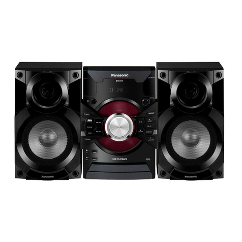
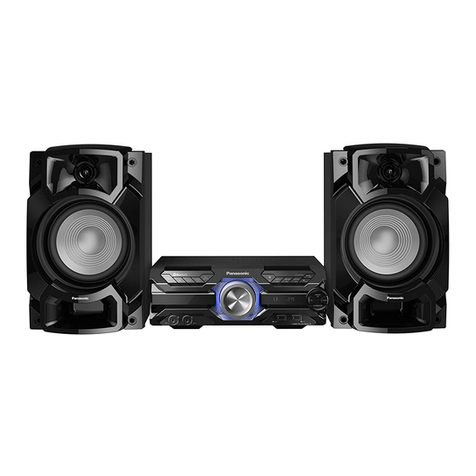
SA-AK15
I Safety PfeGaUtiOnS (rhis"sarety
precaution,'is
apptied
onty
in
usA.)
1. Eefore
servicing,
unplug
the
power
cordto
prevent
an
electricshock.
2. When
replacing
parts,
useonlymanufacturer'srecommended
componentsforsafety.
3. Checkthe
condit¡on
of
the
power
cord.Replace
ifwear
ordamageisevident.
4. After
servicing,
besure
to
restore
thelead
dress,insulation
barriers,insulation
papers,
shields,etc.
5. Beforereturning
the
servrcedequipment
tothecustomer,
besuretomakethefollowing
insulation
resistance
test
to
prevent
the
customerfrom
beingexposedto
ashockhazard
. Insulation
Resistance
Test
1. Unplug
the
power
cordandshort
thetwo
prongs
ofthe
plug
with
a
jumper
wire.
2. f urnonthe
power
switch.
3. Measure
theresistance
valuewith
ohmmeterbetween
the
jumper
AC
plug
andeachexposedmetal
cabinet
part,
such
asscrewheads,
antenna,control
shafts,handle
brackets,etc.Equipmentwith
antenna
term¡nals
shouldread
between
3MQand5.2MOto
allexposed
parts-.
(Fig.
1
)Equipmentwithout
antenna
term¡nals
shouldread
approximatelyinfinity
toallexposed
parts.
(Fig.2)
.Note
:
Some
exposed
parts
may
beisolatedfrom
thechassis
bydesign.Thesewillreadinfinity.
4. lfthemeasurement
isoutsidethe
specifiedlimits,
thereis
apossibility
ofashockhazard.The
equipment
should
berepaired
andrechecked
beforeitisreturned
tothe
customer.
Antenna
Iermrnal
Exposed
melal
part
f¿r/
¡\ I
\-]:'orrmmeter
Fig.1
Resistance-3Mo-5.2Mo
Exposed
melal
part
lfthisoccurs,followthe
procedure
outlinesbelow:
1.Turnoffthe
power.
2.Determinethe
causeoftheoroblemandcorrectit.
3.Turnonthe
power
onceagainafterone
m¡nute.
Note:
Whenthe
protection
circuitry
functions,
theunitwillnotoperateunless
the
power
isfirstturnedoff
and
then
onagain.
I Protection
Circuitry
The
protection
circuitrymayhave
operated¡f
eitherofthefollow¡ng
conditions
arenoticed:
. No
soundisheard
whenthe
power
isturned
on.
. Sound
stopsduring
aperformance.
Thef
unction
ofthiscircuitry
isto
prevent
c¡rcuttry
damageif
,
for
example,
the
positive
and negative
speaker
connectionwires
are
"shorted',,
or
if
speaker
systemswith an impedance
lessthan
the indicatedrated
impedance
ofthe
amplifier
areused.
I Precaution
ofLaser
Diode
CAUTION:
This
unitutrlizes
aclass1laser.Invisrble
laserradiation
isemittedfrom
theoptical
pick
uplens.
When
theunitis
turnedon:
1.Do
notlook
directlyintothe
pick
uplens.
2.Donot
use
opticalinsturments
tolook
atthe
pick
uplens.
3.
Do
notadjust
the
preset
variable
resistor
onthe
pick
up
lens.
4.Donot
disassemble
the
optical
pick
up
unit.
5.lfthe
optical
pick
upisreplaced,
usethemanufacturer's
specifiedreplacement
pick
uponly.
6.Useof
controlor
adjustmentsor
performance
of
procedures
otherthanthose
specified
herein
may
result
inhazardousradiation
exoosure.
CAUTION!
THIS
PRODUCT
UTILIZES
ALASER.
USE
OFCONTROLS
ORADJUSTMENTS
ORPERFORMANCE
OFPROCEDURES
OTHERTHANTHOSE
SPECIFIED
HEREIN
MAY
RESULT
INHAZARDOUS
RADIATION
EXPOSURE.
I Accessor¡es
AC
power
supply
cord
(SJAI72)
.pc. FM
indoor
antenna
(R5A0006)
ñ
AMloopantenna
set
(RSA0022)
.
AMloop
antenna..........1
pc.
' Alvl
antennaholder..........1
pc.
Remote
controltransmitter
(RAK-CH94OWK)
..........1
pc
--"^"
-"t )-t
| --/
'trtt )
\. '/
Batter¡es
IR6/1R6,
AA,
UIV-3]
..........2
pcs.
-3-


