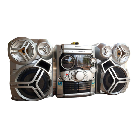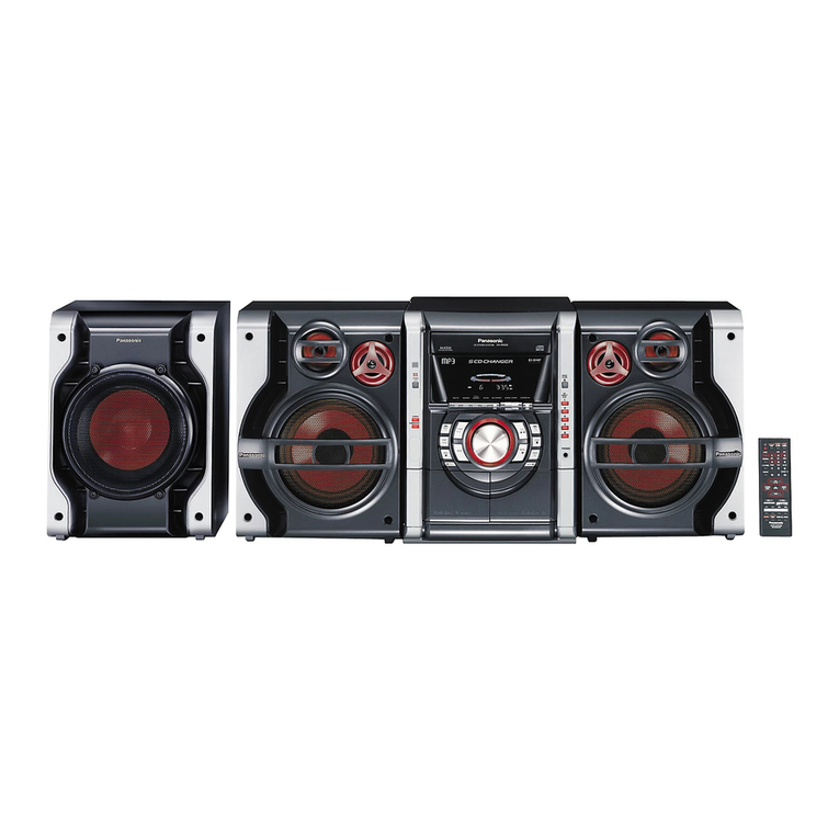
SA-AK66
Beam
source/wave
length
Semiconductor
laser/780
nm
Stereo
20
Hz
-
20
kHz
(+1,
-2
dB)
Wow
and
flutter
Below
measurable
limit
Digital
filter
8
fs
MASH
(1
bit
DAC)
Number
of
channels
Frequency
response
D/A
converter
m@
GENERAL
Power
supply
AC
120
V,
60Hz
Power
consumption
230
W
Power
consumption
in
standby
mode
0.29
W
250
X
332
X
319
mm
9
27/32”
x
13
1/16”
x
12
9/16”
(8.3
kg)
18.3
Ib
Dimensions
(W
x
H
x
D)
Mass
m@
SYSTEM
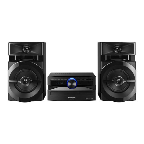
SC-AK66(P)
Music
Center:
SA-AK66(P)
Front
Speaker:
SB-AK66(P)
Center
&
Surround
Speaker:
SB-PT70A
(P)
Music
Center:
SA-AK66(PC)
Front
Speaker:
SB-AK66(P)
Center
&
Surround
Speaker:
SB-PT70A
(P)
SC-AK66(PC)
Notes:
1.
Specifications
are
subject
to
change
without
notice.
Mass
and
dimensions
are
aproximate.
2.
Total
harmonic
distortion
is
measured
by
the
digital
spectrum
analyzer.
A,
WARNING
This
service
information
is
designed
for
experienced
repair
technicians
only
and
is
not
designed
for
use
by
the
general
public.
It
does
not
contain
warnings
or
cautions
to
advise
non-technical
individuals
of
potential
dangers
in
attempting
to
service
a
product.
Products
powered
by
electricity
should
be
serviced
or
repaired
only
by
experienced
professional
technicians.
Any
attempt
to
service
or
repair
the
product
or
products
dealt
with
in
this
service
information
by
anyone
else
could
result
in
serious
injury
or
death.
CONTENTS
Page
F
Safety
Precautlont-s-nsesrceesecenne
scree
cece
cee
ese
ens
2
2
Before
Repair
and
Adjustment
-----------------------------------77222
2227
3
3
Protection
Circuitry
--------------------------rrrrrrrrrernnnnn
nnn
3
.
PCCOS
SONI
So
neene
ttc
ne
ese
a
eens
ce
apes
agree
ps
toe
asecaencena
en
cnents
4
5
Handling
Precautions
For
Traverse
Deck
------------------*+---------""
5
6
Precaution
of
Laser
Diode
---------------------++2222-eeeeeeenennteeeeeeeeenees
6
7
Operation
Procedures
--------------------------neesenneernrrnreren
nnn
nesses
nennes
7
8
Operation
Checks
and
Main
Component
Replacement
Se,
ea
ae
ec
ei
ieee
ab
eae
9
9
Self-Diagnostic
Function
-------------------------renrnennnseee
nce
eeenneceenees
17
10
Description
of
Error
Code
-------------------------22-enreccnsecc
ecco
neccenees
18
1
Safety
Precaution
(This
“Safety
Precaution”
is
applied
only
in
U.S.A.)
Page
11
CD
Test
Mode
Function
------------------------------2--nnnenrrcnon
nn
nrccnnn
es
19
12
Measurements
and
Adjustments
~-----------------------------------------
20
13
Illustration
of IC
#i,
Transistors
and
Diodes
-------------------------
22
14
Terminal
Function
off
IC
iii
-----------r--reerreeceeenettceeteen
tren
ttceetene
23
15
BlOCK:
Disgralin
sssce-s
econ
se
csencsnsecsce
sceketirsensetemn
ses
seurteoneosrauedesosess
26
16
Schematic
Diagram
--------------------------2222reeereeereoeeeeenenennnttttttnnes
33
17
Printed
Circuit
Board
--------------------------nnrnernn
nn
rernrnn
errr
cnrrcnnn
es
46
18
Wiring
Connection
Diagram
----------------------------r-rrnnrr
renner
57
19
Troubleshooting
Guide
---------------------------------r--onnrrnnnnnnrrcnnnn
es
58
20
Parts
Location
and
Replacement
Parts
List
-------------------------
59
1.
Before
servicing,
unplug
the
power
cord
to
prevent
an
electric
shock.
2.When
replacing
parts,
use
only
manufacturer’s
recommended
components
for
safety.
3.
Check
the
condition
of
the
power
cord.
Replace
if
wear
or
damage
is
evident.
4.
After
servicing,
be
sure
to
restore
the
lead
dress,
insulation
barriers,
insulation
papers,
shields,
etc.
5.
Before
returning
the
serviced
equipment
to
the
customer,
be
sure
to
make
the
following
insulation
resistance
test
to
prevent
the
customer
from
being
exposed
to
a
shock
hazard.
