10°C).
-Pb free solder will tend to splash when heated too high (about
1100°F/600°C).
-When soldering or unsoldering, please completelyremove all of
the solder on the pins or solder area, and be sure to heat the
soldering points with the Pb free solder until itmelts enough.
4. Before Repair and Adjustment
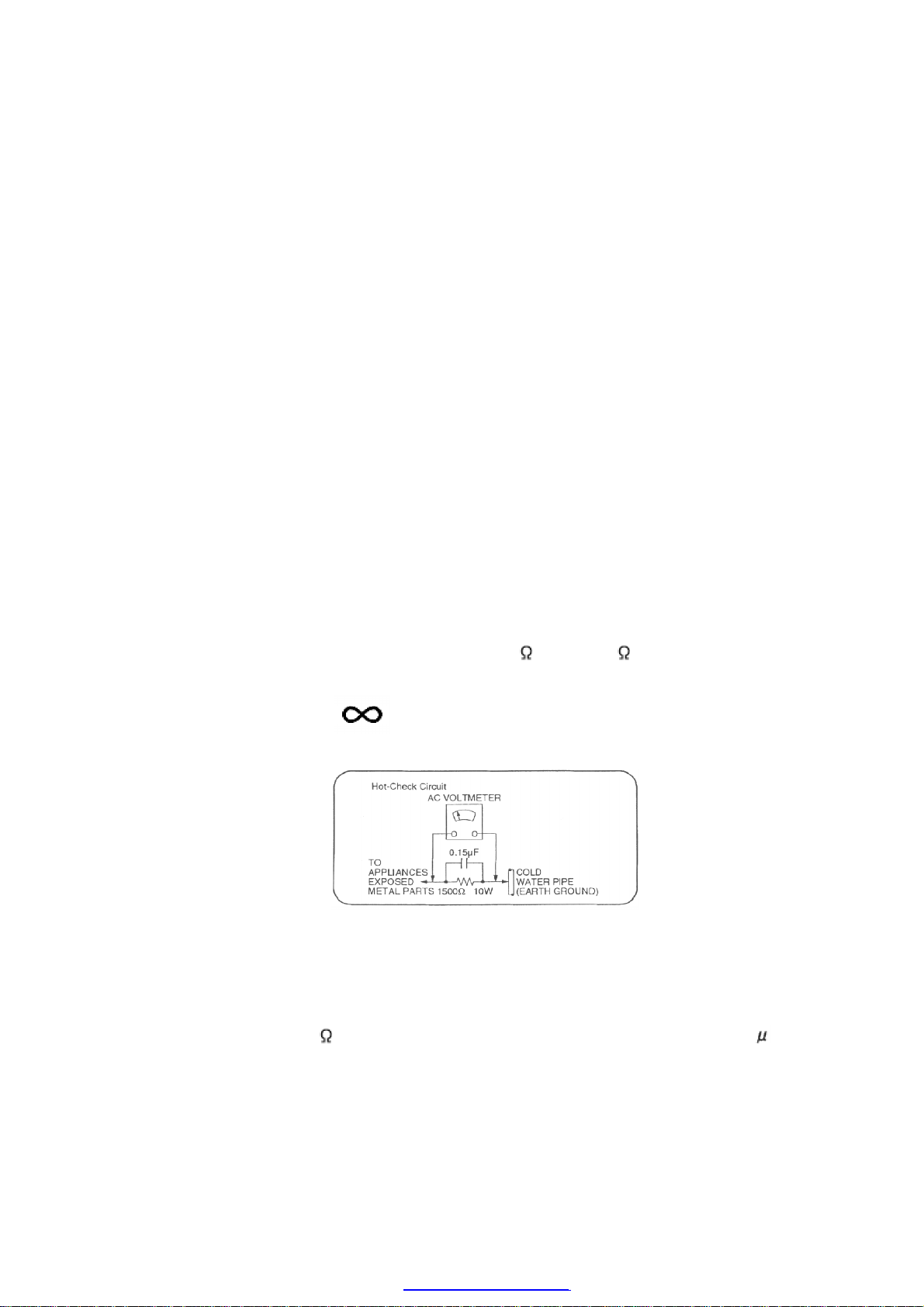
Disconnect AC power, discharge PowerSupplyCapacitors C546~C549 through a 10 , 1 W
resistortoground.
DO NOTSHORT-CIRCUITDIRECTLY (witha screwdriverblade, forinstance), as this may
destroysolidstate devices.
Afterrepairs are completed, restore powergraduallyusing a variac, toavoidovercurrent.
Current consumption at AC220 V, 60 Hz inNO SIGNALmode shouldbe ~620 mA.
5. Protection Circuitry
The protection circuitrymayhave operatedif eitherof the following conditions are noticed:
-Nosound isheard when the power isturned on.
-Stops during aperformance.
The function of this circuitryis toprevent circuitrydamage if, forexample, the positive and
negative speakerconnection wires are “shorted”, orif speakersystems withanimpedance less
thanthe indicatedratedimpedance of the amplifierare used.
If this occurs, followthe procedure outlines below:
1. Turn off the power.
2. Determine the cause of the problem and correct it.
3. Turn on the power once againafter one minute.
Note:
Whenthe protection circuitryfunctions, the unit will not operate unless the poweris first turned
off and thenon again.
6. Connection of the Speaker Cables
-Besure to connect speaker cables before connecting the AC
power supplycord.
-The load impedance of anyspeaker used with thisunitmust be 4 .
-Besure to connect the cablefrom the right speaker to the right
terminal and the cablefrom the left speaker to the left terminal.
1. Stripoff the outer covering, and twist the center conductor. Make
sure the bare ends of the wires are not unravelled. (Iftheyare,
twist them tight again.)
2. Insert the wire to the rear panel of the unitand close the lever.
6
PDFcreated withpdfFactoryProtrialversion www.pdffactory.com