manuals.online logo
Brands
  1. Home
  2. •
  3. Brands
  4. •
  5. Panasonic
  6. •
  7. Telephone
  8. •
  9. Panasonic Easa-Phone VA-123210 Assembly instructions

Panasonic Easa-Phone VA-123210 Assembly instructions

Other manuals for Easa-Phone VA-123210

2

This manual suits for next models

13

Other Panasonic Telephone manuals

Panasonic KX-T7450 User manual

Panasonic

Panasonic KX-T7450 User manual

Panasonic KX-T7565NE User manual

Panasonic

Panasonic KX-T7565NE User manual

Panasonic KX-TG7301FX User manual

Panasonic

Panasonic KX-TG7301FX User manual

Panasonic VoiceSonic VB-42210 User manual

Panasonic

Panasonic VoiceSonic VB-42210 User manual

Panasonic VoiceSonic VB-42210 User manual

Panasonic

Panasonic VoiceSonic VB-42210 User manual

Panasonic KX-TD816 User manual

Panasonic

Panasonic KX-TD816 User manual

Panasonic DBS 576 Section 300 User manual

Panasonic

Panasonic DBS 576 Section 300 User manual

Panasonic KX-T7320 User manual

Panasonic

Panasonic KX-T7320 User manual

Panasonic KX-TDA50 User manual

Panasonic

Panasonic KX-TDA50 User manual

Panasonic KX-T7636 User manual

Panasonic

Panasonic KX-T7636 User manual

Panasonic KX-FKN523 User manual

Panasonic

Panasonic KX-FKN523 User manual

Panasonic EASA-PHONE KX-T2365A User manual

Panasonic

Panasonic EASA-PHONE KX-T2365A User manual

Panasonic KX-TCA256X User manual

Panasonic

Panasonic KX-TCA256X User manual

Panasonic KX-TGF870C User manual

Panasonic

Panasonic KX-TGF870C User manual

Panasonic DBS Series Installation guide

Panasonic

Panasonic DBS Series Installation guide

Panasonic KX-TDA100D Specification sheet

Panasonic

Panasonic KX-TDA100D Specification sheet

Panasonic KX-TGP500 B04 User manual

Panasonic

Panasonic KX-TGP500 B04 User manual

Panasonic KX-TS730 User manual

Panasonic

Panasonic KX-TS730 User manual

Panasonic KX-T7565 User manual

Panasonic

Panasonic KX-T7565 User manual

Panasonic KX-TD500 User manual

Panasonic

Panasonic KX-TD500 User manual

Panasonic KX-NS700 User manual

Panasonic

Panasonic KX-NS700 User manual

Panasonic KX-TD7680 - Digital Wireless Telephone User manual

Panasonic

Panasonic KX-TD7680 - Digital Wireless Telephone User manual

Panasonic KX-NT300 series Specification sheet

Panasonic

Panasonic KX-NT300 series Specification sheet

Panasonic UTG 200B User manual

Panasonic

Panasonic UTG 200B User manual

Popular Telephone manuals by other brands

Philips BaseLine Pro manual

Philips

Philips BaseLine Pro manual

V-tech i6772 user guide

V-tech

V-tech i6772 user guide

BT FREELANCE XD 5100 quick start guide

BT

BT FREELANCE XD 5100 quick start guide

Uniden 1360 user guide

Uniden

Uniden 1360 user guide

Fanvil D800 user manual

Fanvil

Fanvil D800 user manual

Avaya IP500 user guide

Avaya

Avaya IP500 user guide

NEC Univerge SV9100 installation manual

NEC

NEC Univerge SV9100 installation manual

Amanda MiniSOHO Installation and programming manual

Amanda

Amanda MiniSOHO Installation and programming manual

Hitachi SelecSet 900 Series user guide

Hitachi

Hitachi SelecSet 900 Series user guide

mPTech HAMMER BS21 quick start guide

mPTech

mPTech HAMMER BS21 quick start guide

NEC 2000IVX user guide

NEC

NEC 2000IVX user guide

ooma Phone Genie quick start guide

ooma

ooma Phone Genie quick start guide

Siemens Gigaset S450 user guide

Siemens

Siemens Gigaset S450 user guide

Clarity RC100 operating instructions

Clarity

Clarity RC100 operating instructions

GE 2-9480 user guide

GE

GE 2-9480 user guide

Geemarc PHOTOPHONE 155 user guide

Geemarc

Geemarc PHOTOPHONE 155 user guide

Interquartz Gemini IQ333 operating instructions

Interquartz

Interquartz Gemini IQ333 operating instructions

SSS Siedle HT 840-0 operating instructions

SSS Siedle

SSS Siedle HT 840-0 operating instructions

manuals.online logo
manuals.online logoBrands
  • About & Mission
  • Contact us
  • Privacy Policy
  • Terms and Conditions

Copyright 2025 Manuals.Online. All Rights Reserved.

Installation and
Programming
Manual
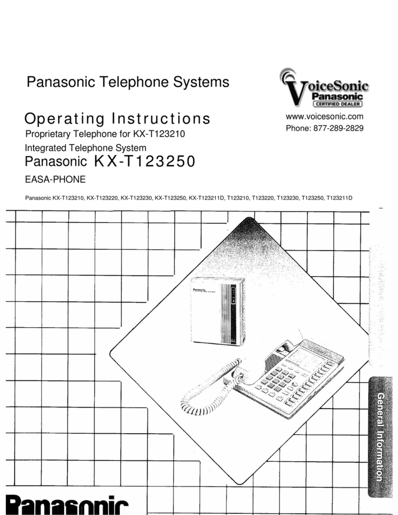
Easa-Phone
Key Telephone System
VA-1232
MODEL VA-123210
VA-30920
VA-12020
VA-12021
VA-12022
VA-12022-B
VA-82430
VA 82444
VA-30940D
VA-30941D
VA-30942D
VA-30965
VA-30960
VA-20861 Panasonic
3DQDVRQLF7HOHSKRQH6\VWHPV
www.voicesonic.com
Phone 877-289-2829
Thank you for purchasing the Panasonic Easa-Phone VA-1232, Key Telephone System.
This system can connect eight central office lines and twenty four key telephones and DSS, door box, external paging amp and
external music source can be added.
Please read this manual carefully before the installation of this system.
Please follow the installation procedure described below.
Before connecting telephone lines, inform to telephone company of the following.
COLl COL7
Telephone numbers COL2 COL8
COL3 COL9
COL4 COLIO
COL5 COLI 1
COL6 COL12
Model number Panasonic VA-1 232 _
FCC registration number for VA-1232 KSU from factory ACK8GR-17656-KF-E
When modified to PBX (See page 18) ACK8GR-17655-MF-E
Factory interface code
Service order code
Ringer equivalence
Required network interface jack
02 LS2
9.OF
0.48
USOC RJI IW, RJI IC
1. SYSTEMCONNECTIONLAYOUT ....................................................... 1
2. INSTALLATION OF KEY SERVICE UNIT ................................................. 3
How to wall mount the key service unit ................................................... 3
3. INSTALLATIONOFKEYTELEPHONE.. ................................................. 5
How to wall mount the key telephone .................................................... 5
4. WIRINGCONNECTIONS ............................................................. 8
Connection between the KSU, Key TEL and CO/PBX line ....................................... 8
Typeofwires ..................................................................... 7
Wiringcables.. ................................................................... 8
5. CONNECTION OF OPTIONAL UNlT ..................................................... 9
Variation of card connection .......................................................... 9
Extension of CO/PBX line ............................................................ 10
Connection of direct station selector ..................................................... 11
Connections of single line telephone or -2 Key TELs/2 SLTs ...................................... 12
Connection of door box. ............................................................. 13
Connections of sensor and door opener. ................................................... 14
ConnectionofSMDR ............................................................... 15
External music on hold source and external paging system ....................................... 17
Set up for key service unit ............................................................ 18
8. CONNECTION OF POWER FAILURE UNIT ................................................ 19
7. SPECIFICATIONS OF SYSTEM ......................................................... 21
Modules and system configuration ....................................................... 21
System capacity and specifications ....................................................... 22
Check list of parts. ................................................................. 23
.............
le for initial set ...... 7
............ Priority
..................................... 152
........................ ications ......... 154
.........................
ing .............
...............
..............
Ut .......................
setting .................
~~~u~a~i~~ ...............
ialing ...................
....................
tion ..................
ing .......................
.......................
line.. ..................
e line s@i~~~i~~ .......
s~~~a~§. ................
se ......................
......................
assign ......................
call
ringing ...................
~ig~a~i~g .................... 67
rbQXCall.. ......................
~~~gi~~ .......................
aging .........................
t service setting .............. 7
tservice
................... 7
res~~~~~io~ class .............
Install the key service unit (KSU) on the wall according to the following procedure.
@ Slide the two hooks securing the KSU cover and the key service unit in the arrow direction, then remove the cover.
@ Place template against wall and install the four wood screws. Use the wood screw installation jig provided inside the
key service unit when installing the wood screws. ‘Z.
@ Install the key service unit by hooking the four installation holes at the bottom of the key service unit to the four wood ‘,ii
screws, then tighten the two left side wood screws completely.
“Be
sure
the power switch is OFF, before installation.”
Avoid installing in the following places. (Doing so may result in malfunction, noise, or discoloration)
a) In direct sunlight, hot, cold, or humid places. (Temperature range: 32’F - ‘l04’F)
b) Fulfuric gases produced in areas where there are thermal springs, etc. may damage the equipment or contacts.
c) Places in which shocks or vibrations are frequent or strong.
d) Dusty places, or places where water or oil may come into contact with the unit.
e) Near high-frequency sewing machines or electric welders.
f) On or near computers, telexs, or other office equipment, as well as microwave ovens or air conditioners. (It is preferable
not to install in the same room with the above equipment.)
;.
g) Near radio broadcast antennas. (including short wave)
h) Install at least 6 feet from radios and televisions. (both the key service unit and
key
telephones)
i) Do not obstruct area around the
key
service unit. (for reasons of maintenance and inspection - be especially careful to
allow space for cooling above
and at
the sides of the key service unit).
Install the key telephone on the wall according to the following procedure.
@ Pull handset guide, turn it upside
down, then insert it into its position.
@ Push the hooks at two places, then
remove the adapter.
@ Turn the adapter upside down, insert
the guides into two adapter mounting
holes provided at the lower portion of
the key telephone, then push in the
adapter.
@ Place the mounting holes of the
bracket over the studs of the modular
jack and pull the phone downward to
secure in place.
Short station cords are provided to
attach the key telephone.
Handset cord obtainable on the market.
VAX-20884 7 feet
VAX-20885 15 feet
Make connections between the KSU, Key TEL and the central office/PBX line (CO/PBX) according to the following procedure.
Connect COL No. 1 through No. 8
jacks provided inside the KSU to the
CO/PBX line, respectively.
onnect EXT No. IO through No. 33
is desirable to use an LCD
display type key telephone (VA-1 2022
43) that is used for the
ING purpose described
later. (see page 28.)
a Push in the cables from the top of
the cable guide.
c$ Remove the clamp plate, insert
the cords, then reinstall the clamp
plate over the cords and secure
into place with the screw.
Keep the loop wire resistance to the
key telephone furthest from the key
service unit less than 40 ohms. (Max.
1100 feet with 22 AWG cable)
Do not wire the telephone cabls in
parallel with the AC power source,
s
computer, telex etc. If the cables run
near those wires, shield the cables
within metal tubing or use shielded
cable and ground the shields.
When cables run on the floor, use pro-
tectors or the like to protect the wires
where they may be stepped on. Avoid
wiring under carpets.
When using an AC power supply (AC
12OV), make sure the unit is ground.
To key telephone
(a) If the key service unit and the exten-
sion are within 25 feet, use the cable
supplied (7 feet, 15 feet or 25 feet).
(See page 21)
(b) Station cord and Handset cord
Depending on the connection and
length, 4 types of station cords and 2
types of Mandset cords are available.
(See page 21)
(c) When the key service unit and the
extension are apart by more than 200
feet, please use quad cable. Quad
cables assure proper operation over
long distance than flat cables.
In this case, use connector (Modu-
lar-screw).
ing cables, either of the
following can be used (
Flat cable obtainable on the market.
les ex~~a~at~~~
rng quad cable depends upon the
I
KSU I
1
L 25 FEET
r
__-----
Max option<
cord)
IT
200 FEET
(Max flat
cable)
MODULAR
CONNECTOR
MODULAR
CONNECTOR
up to 1100 FEET
(Max quad cable)
TERMINAL BOX
MODULAR
CONNECTOR SCREW TERMINAL BOX
wiring length.
Make sure that the quad cables are
twisted pair or shielded twisted pair.
ate: Quad cables are not used for attach-
ing modular terminals.
lTerminall Modular Modular 1 Modular Screw
OTE Use the four conductor type Use this type when the quad cable
inline coupler. and door box unit is connected.
Flat cable Flat cable Flat cable Quad cable
COUPLlNG
OF CABLE