5
1. Model number
1.1 Model number
A K T 2 1 0
(1) (2) (3) (4) (5) (6)
(1) Supply voltage ---------------------- 1: 100 to 240V AC 2: 24V AC/DC
(2) Input type ----------------------------- 1: Multi-input (Thermocouple, RTD, DC current and DC voltage
can be selected by keypad operation. For DC current input, 50
shunt resistor (AKT4810, sold separately) must be connected
between input terminals.)
(3) Control output (OUT1) ----------- 1: Relay contact 2: Non-contact voltage (Voltage output for SSR
drive) 3: DC current
(4)Alarm output ------------------------- 0: Not available (When both Healing/Cooling control and Serial
communication are selected)
1:A1 output or A2 output (However, if Healing/Cooling control
is selected, onlyA2 output is available. If Serial communication
is selected, onlyA1 output is available)
2:A1 output +A2 output (When neither Healing/Cooling control
nor Serial communication is selected)
(5) Heating/Cooling control (OUT2) output: 0: Not available 1: Relay contact
(6) Serial communication ------------- Blank: Not available 1: Applied
1.2 How to read the rated label
The rated label is attached to the case and the inner assembly.
(For case) (For inner assembly)
(Fig. 1.2-2)
(Fig. 1.2-1)
2. Name and functions of the sections
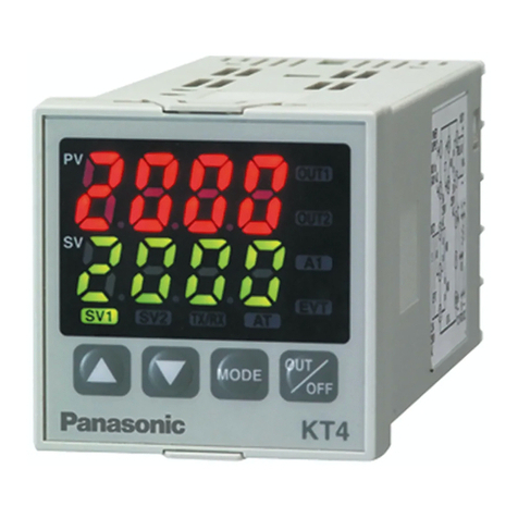
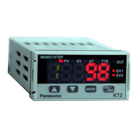
1PV/SV display (red): Indicates the PV (Process variable)
and SV (Main set value). During setting mode, characters
and set value of each setting item are indicated alternately.
2MEMO/STEP display (green): Indicates memory number
during fixed value control. Indicates step number during
program control.
3PV indicator (red): Lights when the PV (Process variable)
is indicated.
4SV indicator (green) : Lights when SV (main set value) is indicated.
5AT indicator (yellow) : Flashes during AT (auto-tuning).
6T/R indicator (yellow): Flashes during Serial communication.
(Lit while sending data, Unlit while receiving data)
7OUT indicator (green):Lights when control output or OUT1 (Heating side, Heating/Cooling control
option) is ON. (For DC current output type, it flashes corresponding to the
manipulated variable in 0.25 second cycles)
8EV1 indicator (red) : Lights when Event output 1 or OUT2 (Cooling side, Heating/Cooling control
option) is ON.
9EV2 indicator (red) : Lights when Event output 2 is ON.
10 Increase key ( ) : Increases the numeric value.
11 Decrease key ( ) : Decreases the numeric value.
12 Mode key ( ) : Selects the setting mode or registers the set value.
(Bypressing the Mode key, the set value or selected value can be registered)
13 OUT/OFF key ( ) : The control output OUT/OFF or program control RUN/STOP can be switched.
1
2
3 4 5 6 7
8
9
10 11 12 13
1
2
1: Model number, supply
voltage, input type, output
type, etc. are entered
2: Lot number is entered.
(Example)
Supply voltage: 100 to 240V AC
Multi-input
Relay contact output
A1 output + A2 output
Heating/Cooling control is not added
Serial communication is not added
(Fig. 2-1)

