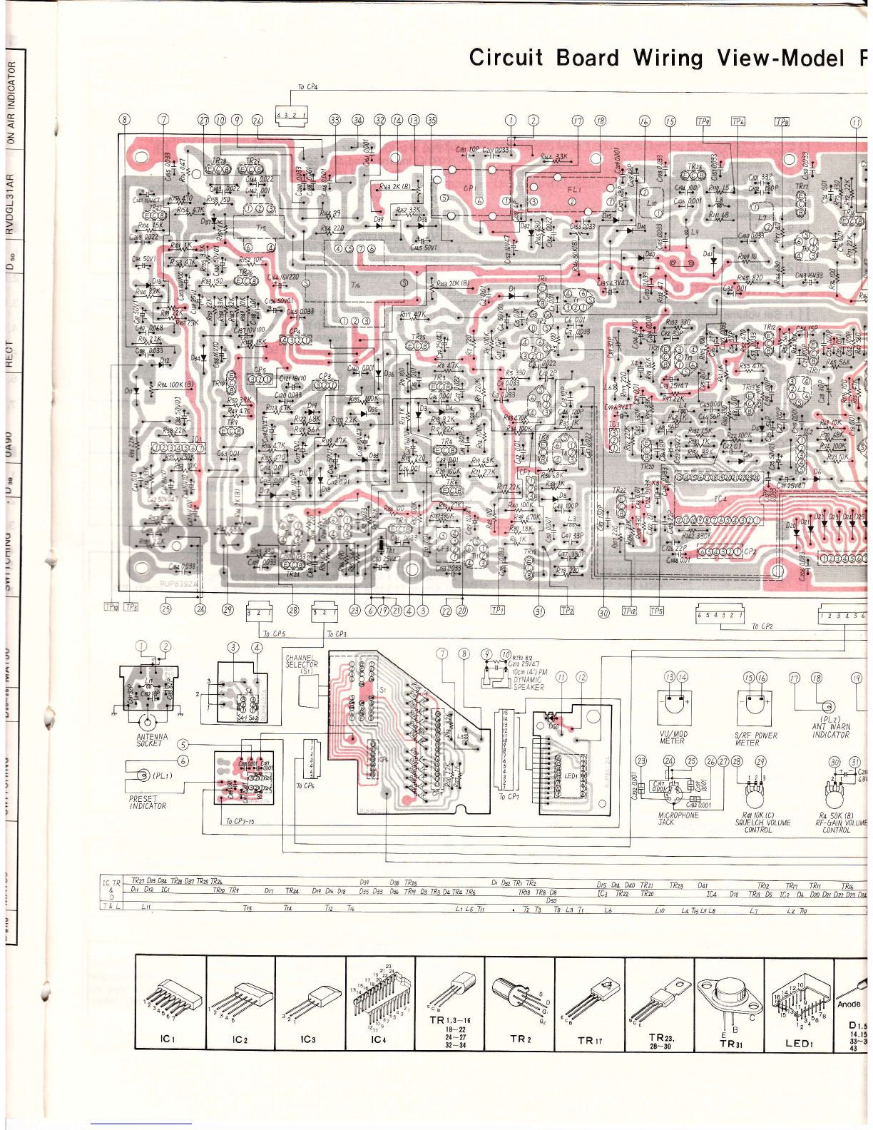
IFEATURES
. 40 channels
. L.E.D. (Light Emitting Diode) Digital Channel Display
. Preset System for all zl0 channels
. RF Gain Control
. Two llluminated Meters (S/RF Power and VU/MOD)
. Squelch Control
. NB (Noise Blanking)/ANl (Automatic Noise Limiter)
. Antenna Warning lndicator
ICONTROLS AND THEIR FUNCTION
OPush-To-Talk Switch
To transmit, speak into the microphone while pressing this switch.
To receive, release it.
@Microphone
Speak in a normal voice, directly into the microphone. Hold the
microphone about an inch or two away from your mouth.
@Sfnf Power Meter
This meter has two functions: When receiving, it indicates the
relative strength of received signals in '"S" units. "S1 " indicates a
weak or distant station; a reading of "S9" would indicate a local
station. When transmitting, it indicates the relative RF power
output. A reading in the upper-portion of the meter indicates proper
transmission power.
@vu/MoD Meter
lndicates the relative strength of your voice into the microphone
during transmission (MOD), and the relative strength of the
speaker power output during reception (VU). While speaking into
the microphone, adjust the voice strength so that the pointer stays
in the green ranga,i.
@Antenna Warning (ANT WARN) lndicator
This indicator shows antenna matching condition.
@On-Air lndicator
Lights up when the Push-To-Talk Switch on the Microphone is in
the transmit mode.
OOigitat Channel Display Panel
lndicates which channel the unit is turned to for transmit and
recieve. But, it displays nothing when the Preset Channel Push-
switch is ON.
@Channel Selector
Selects any one of the 40 channels for transmit and receive.
@Microphone Socket
Plug the microphone into this socket, and secure the plug with the
captive screw-ring. This units is totally inoperable if the micro-
phone is disconnected.
Note: Do not us other microphones with dissimilar characteristics.
@ Preset Channel Pushswitch I
When pushing this pushswitch, the indicator on it lights up and
channel display disappears, you can then communicate on any
channel preset with the Preset Channel Selector, regardless of the
Channel Selector position.
. On-Air lndicator
. llluminated Preset Channel Pushswitch
. AC/DC Power Operation
. Positive, or Negative Ground Operation
- External Speaker Jack
. Dynamic Microphone with Push-To-Talk Switch
. 4" Diameter Self-Contained Speaker
@Noise Blanking (NB)/Automatic Noise Limiter (ANL) Push-
switch
Normally, leave the switch in the "OFF" position.
Set this switch in the "ON" position to reduce noise caused by
electric motors, ignition, lightning, etc. . . .
@On/Off Switch andtolume Control
Turn the control clockwise to turn the set on andto adiust the
receiver's sound level.
@Squelch Control
Use to cut background noise when no signals are being. The
degree of sensitivity to incoming signals is adjustable; a clock-
wise position provides maximum squelch, but in this position, it
may also cut out weak incoming signals.
@RF Gian Control
Adjust the receiver sensitivity for distortion{ree reception.
Normally, should be set in the MAX position. lf received signals are
too strong to understand, slowly rotate this control counter-
clockwise until clear sound is obtained.
@Preset ehannel Selector
Preselects any one of the 40 channels for the Preset Channel
operation. Simply turning the Preset Channel Pushswitch on
adjusts, the transceiver to a preselected channel at any time.
@Antenna Socket
Any 50 O antenna, designed for CB applications, may be con-
nected.
@External Speaker Jack
When an external 8 O speaker is connected, the built-in speaker is
automatically disconnected.
@DC Power Cord Connector
@DC Fuse Holder
Suppliedwitha2Afuse.
@AC Power Cord
@AG Fuse Holder
Suppliedwitha2Afuse.
@ACIDC Selctor Switch
@DC Power Cord
This unit is designed to operate on 1 3.8 V, DC. Connect this cord to
a 12 V battery, or other 12 V, DC power source. For a vehicle or
boat with a 24 V battery, connect the unit through a 24 V, DC to 12
V, DC converler, or to a 12 V section ot a24V electrical system.
(D(}(9
(,
r_,
\/
@o@
[Z nJ-eooo