Read the operating instructions for the unit and all other
components of your car audio system carefully before
using the system. They contain instructions about
how to use the system in a safe and effective manner.
Panasonic assumes no responsibility for any problems
resulting from failure to observe the instructions given
in this manual.
This manual uses pictographs to show you how to use
the product safely and to alert you to potential dangers
resulting from improper connections and operations.
The meaning of the pictographs are explained below.
It is important that you fully understand the meanings
of the pictographs in order to use this manual and the
system properly.
Safety Information
This pictograph intends to alert you to
the presence of important operating
instructions. Failure to heed the
instructions may result in severe injury or
death.
This pictograph intends to alert you to
the presence of important operating
instructions. Failure to heed the
instructions may result in injury or
material damage.
Warning Caution
1 2
Do not disassemble or modify the unit.
Do not disassemble, modify the unit or attempt to
repair the product yourself. If the product needs to
be repaired, consult your dealer or an authorised
Panasonic Service Center.
Do not use the unit when it is out of order.
If the unit is out of order (no power, no sound) or
in an abnormal state (has foreign objects in it, is
exposed to water, is smoking, or smells), turn it off
immediately and consult your dealer.
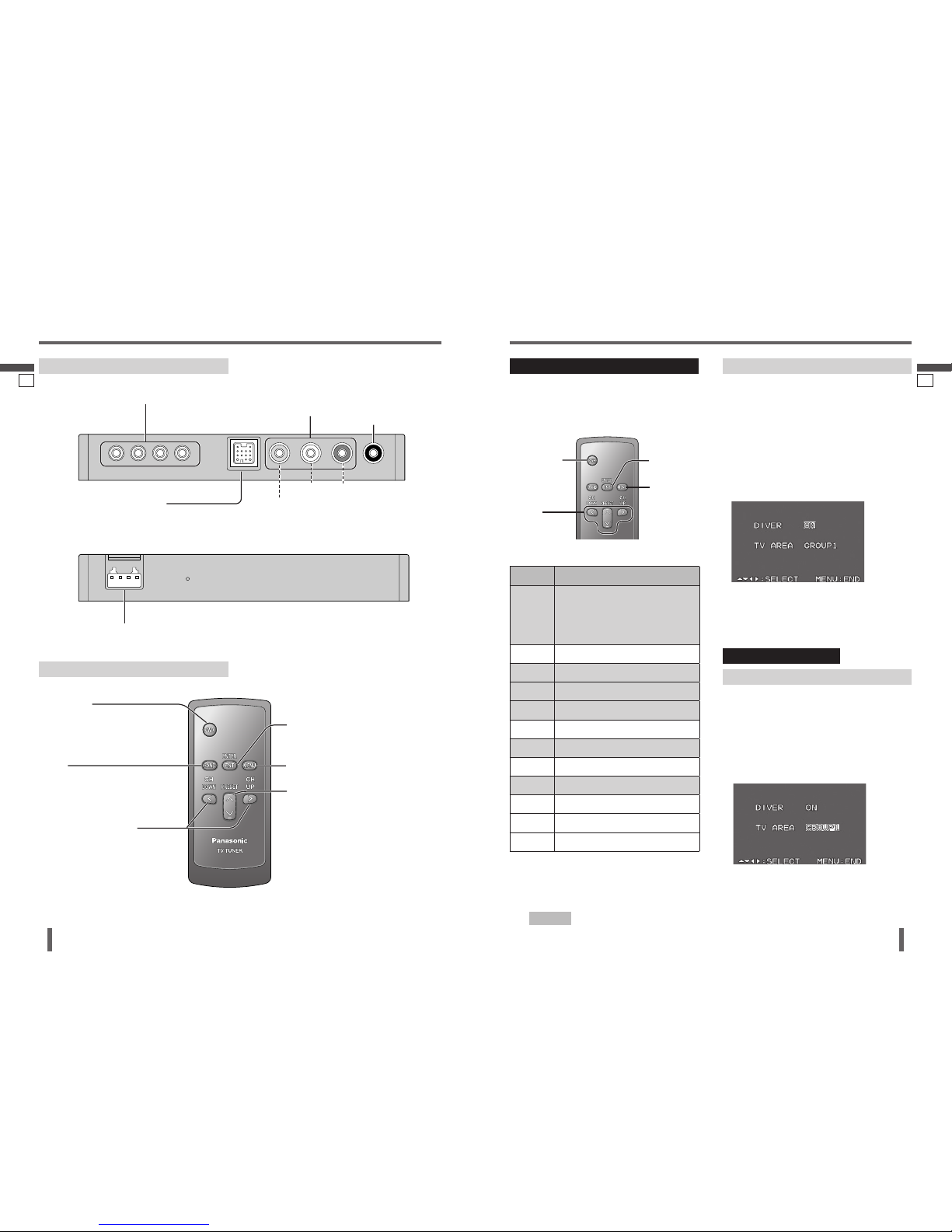
The remote control unit should not lie about in the
car.
If the remote control unit lies about, it could fall on
the floor while driving, get wedged under the brake
pedal, and lead to a traffic accident.
Refer fuse replacement to qualified service
personnel.
When the fuse blows out, eliminate the cause and
have it replaced with the fuse prescribed for this unit
by a qualified service engineer. Incorrect replacement
of the fuse may lead to smoke, fire, and damage to
the product.
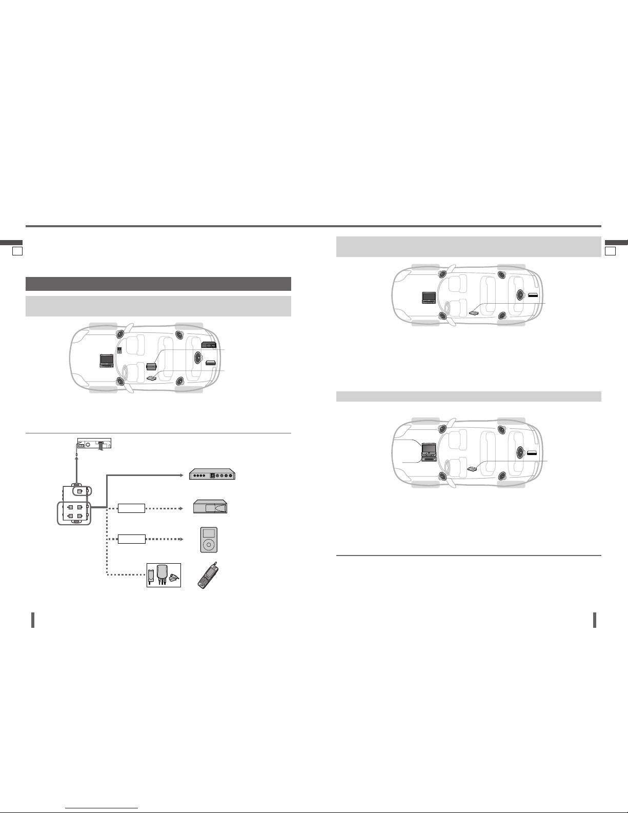
When you connect external devices (option), be
sure to connect the parking brake (side brake)
connection lead.
To ensure safety, never attempt to preset channels
while you are driving.
Observe the following warnings when using the
unit.
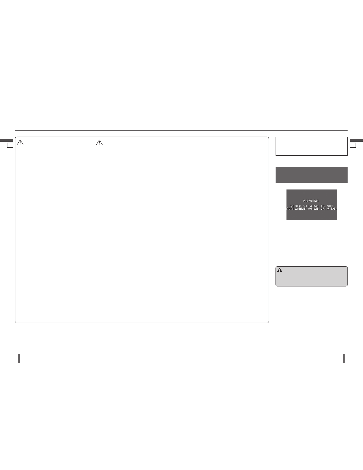
The driver should neither watch the display nor
operate the system while driving.
Watching the display or operating the system will
distract the driver from looking ahead of the vehicle
and can cause accidents. Always stop the vehicle
in a safe location and use the parking brake before
watching the display or operating the system.
Use the proper power supply.
This
product
is designed for operation with a negative
grounded 12 V DC battery system. Never operate this
product with other battery system, especially a 24 V
DC battery system.
Keep a battery away from children to avoid the risk
of accidents. If an infant ingests a battery, please
seek immediate medical attention.
Batteries and insulation film can be ingested, so keep
them out of the reach of infants. If and infant ingests
a battery or insulation film, please seek immediate
medical attention.
Warning
Observe the following warnings when installing.
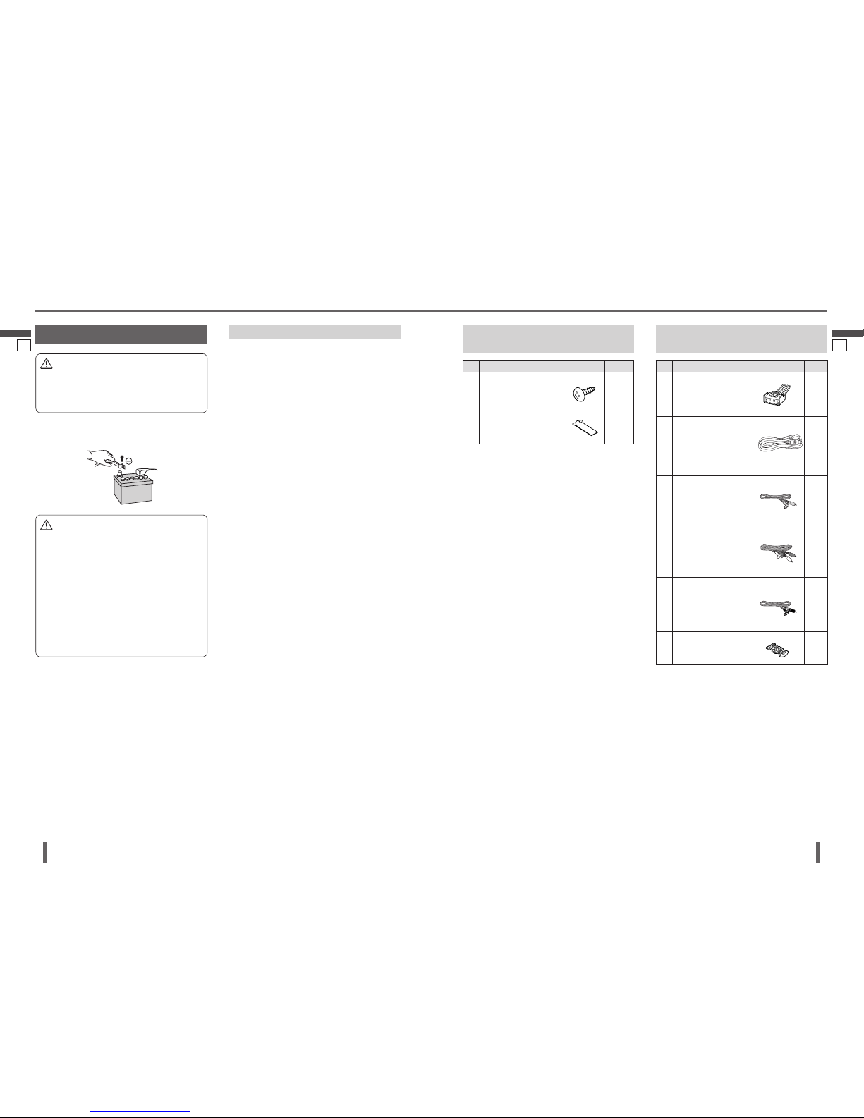
Disconnect the lead from the negative () battery
terminal before installation.
Wiring and installation with the negative () battery
terminal connected may cause electrical shock and
injury due to a short circuit.
Some cars equipped with the electrical safety
system have specific procedures of battery terminal
disconnection.
FAILURE TO FOLLOW THE PROCEDURE MAY
LEAD TO THE UNINTENDED ACTIVATION OF THE
ELECTRICAL SAFETY SYSTEM RESULTING IN
DAMAGE TO THE VEHICLE AND PERSONAL INJURY
OR DEATH.
Never use safety-related components for
installation, grounding, and other such functions.
Do not use safety-related vehicle components (fuel
tank, brake, suspension, steering wheel, pedals
airbags, etc.) for wiring or fixing the product or its
accessories.
Installing the product on the air bag cover or in a
location where it interferes with airbag operation is
prohibited.
Check for piping, gasoline tank, electric wiring, and
other items before installing the product.
If you need to open a hole in the vehicle chassis to
attach or wire the product, first check where the wire
harness, gasoline tank, and electric wiring are located.
Then open the hole from outside if possible.
Never have the power cord branched to supply other
equipment with power.
After installation and wiring, you should check the
normal operation of other electrical equipment.
The continuation of their using in abnormal conditions
may cause fire, electrical shock or a traffic accident.
In the case of installation to an airbag-equipped
car, confirm warnings and cautions of the vehicle
manufacturer before installation.
Make sure the leads do not interfere with driving or
getting in and out of the vehicle.
Insulate all exposed wired to prevent short
circuiting.
Never try to repair the unit by yourself because it is
dangerous to do so.
Warning
This unit cannot be operated alone.
This unit is designed for users to connect one or more system devices to Panasonic car audio/AV unit at the same
time. For more details about safety information, refer to the operating instructions for the connected devices.